Asus P8H77-V User Manual
Hide thumbs
Also See for P8H77-V:
- User manual (1 page) ,
- Manual (150 pages) ,
- Benutzerhandbuch (150 pages)
Table of Contents
Advertisement
Quick Links
Advertisement
Table of Contents

Subscribe to Our Youtube Channel
Related Manuals for Asus P8H77-V


Summary of Contents for Asus P8H77-V
- Page 1 P8H77-V...
- Page 2 Product warranty or service will not be extended if: (1) the product is repaired, modified or altered, unless such repair, modification of alteration is authorized in writing by ASUS; or (2) the serial number of the product is defaced or missing.
-
Page 3: Table Of Contents
Contents Safety information ...................... vi About this guide ......................vii P8H77-V specifications summary ................ix Package contents ..................... xiii Chapter 1: Product introduction Special features .................... 1-1 1.1.1 Product highlights ................1-1 1.1.2 ASUS DIGI+ VRM ................1-3 1.1.3 ASUS Quiet Thermal Solution............1-4 1.1.4... - Page 4 Managing and updating your BIOS ............. 2-1 2.1.1 ASUS Update utility ................ 2-1 2.1.2 ASUS EZ Flash 2 ................2-2 2.1.3 ASUS CrashFree BIOS 3 utility ............2-3 2.1.4 ASUS BIOS Updater ............... 2-4 BIOS setup program ..................2-6 Main menu ....................2-10 2.3.1 System Language [English] ............
- Page 5 2.7.8 Boot Option Priorities ..............2-29 2.7.9 Boot Override ................2-29 Tools menu ....................2-30 2.8.1 ASUS EZ Flash 2 Utility ..............2-30 2.8.2 ASUS O.C. Profile ................. 2-30 2.8.3 ASUS SPD Information ..............2-30 Exit menu ....................2-31 Appendices Notices ........................
-
Page 6: Safety Information
Safety information Electrical safety • To prevent electrical shock hazard, disconnect the power cable from the electrical outlet before relocating the system. • When adding or removing devices to or from the system, ensure that the power cables for the devices are unplugged before the signal cables are connected. If possible, disconnect all power cables from the existing system before you add a device. -
Page 7: About This Guide
Refer to the following sources for additional information and for product and software updates. ASUS websites The ASUS website provides updated information on ASUS hardware and software products. Refer to the ASUS contact information. Optional documentation Your product package may include optional documentation, such as warranty flyers, that may have been added by your dealer. -
Page 8: Conventions Used In This Guide
Conventions used in this guide To ensure that you perform certain tasks properly, take note of the following symbols used throughout this manual. DANGER/WARNING: Information to prevent injury to yourself when trying to complete a task. CAUTION: Information to prevent damage to the components when trying to complete a task IMPORTANT: Instructions that you MUST follow to complete a task. -
Page 9: P8H77-V Specifications Summary
Due to the CPU behavior�� DDR3 2133/1866 MHz memory module will run at DDR3 2000/1800 MHz fre�uency as default. • Refer to Refer to www.asus.com for the latest Memory QVL (Qualified Vendors List). • When you install a total memory of 4GB capacity or more�� Windows When you install a total memory of 4GB capacity or more��... - Page 10 Windows ® ASUS DIGI+ VRM ASUS uni�ue features - ASUS DIGI+ VRM: Digital Power Design for the CPU and iGPU - ASUS 6+1+2 Phase Power Design ASUS Protect 3.0 - EPU - ASUS Anti-Surge Protection - Low EMI...
- Page 11 SFS (Stepless Fre�uency Selection): - BCLK/PCIE frequency tuning from 80MHz up to 300MHz at 1MHz increment Overclocking Protection: - ASUS C.P.R.(CPU Parameter Recall) Back panel I/O ports 1 x PS/2 keyboard / mouse combo port 1 x Optical S/PDIF output port...
- Page 12 BIOS features 64 Mb Flash ROM, UEFI AMI BIOS, PnP, DMI 2.0, WfM 2.0, SM BIOS 2.6, ACPI 2.0a, Multi-language BIOS, ASUS EZ Flash 2, ASUS CrashFree BIOS 3, F12 PrintScreen Function, F3 Shortcut function, and ASUS DRAM SPD (Serial Presence Detect) memory...
-
Page 13: Package Contents
USB910 USB78 USB56 SPDIF_OUT CLRTC AAFP PANEL ASUS P8H77-V motherboard 2 x Serial ATA 6 Gb/s cables 1 x I/O Shield User Guide Support DVD • If any of the above items is damaged or missing, contact your retailer. •... -
Page 15: Chapter 1: Product Introduction
Smart Response Technology is supported by 3rd/2nd generation Intel Core™ processor ® family on Windows 7™ operating systems. ® ** Operating systems must be installed on the HDD to launch Intel Smart Response Technology. The capacity of the SSD is reserved for caching function. ASUS P8H77-V... -
Page 16: Intel Smart Connect Technology
Complete USB 3.0 Integration Double USB Access�� Double Convenience ASUS facilitates the strategic USB 3.0 accessibility for both the front and rear panel – 4 USB 3.0 ports in total. Experience the latest plug & play connectivity at speeds up to 10 times faster than USB 2.0. -
Page 17: Asus Digi+ Vrm
AI Suite II One-stop Access to Innovative ASUS Features With its user-friendly interface, ASUS AI Suite II consolidates all the exclusive ASUS features into one simple to use software package. It allows you to supervise overclocking, energy management, fan speed control, and voltage and sensor readings. This all-in-one software offers diverse and ease to use functions, with no need to switch back and forth between different utilities. -
Page 18: Asus Turbov
ASUS TurboV Feel the adrenaline rush of real-time OC-now a reality with the ASUS TurboV. This easy OC tool allows you to overclock without exiting or rebooting the OS; and its user-friendly interface makes overclock with just a few clicks away. Moreover, the ASUS OC profiles in TurboV provides the best O.C. -
Page 19: Other Special Features
DVD or USB flash disk that contains the latest BIOS file. ASUS EZ-Flash 2 ASUS EZ Flash 2 is a user-friendly utility that allows you to update the BIOS without using a bootable floppy disk or an OS-based utility. -
Page 20: Before You Proceed
The motherboard is European Union’s Energy-related Products (ErP) ready, and ErP requires products to meet certain energy efficiency requirement in regards to energy consumptions. This is in line with ASUS vision of creating environment-friendly and energy-efficient products through product design and innovation to reduce carbon footprint of the product and thus mitigate environmental impacts. -
Page 21: Motherboard Overview
Screw holes Place six screws into the holes indicated by circles to secure the motherboard to the chassis. DO NOT overtighten the screws! Doing so can damage the motherboard. Place this side towards the rear of the chassis P8H77-V ASUS P8H77-V... -
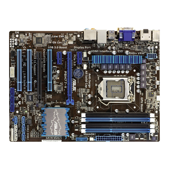
Page 22: Motherboard Layout
DIGI +VRM SPDIF_O EATX12V _HDMI MemOK! DRAM_LED USB3_12 LAN1_USB12 AUDIO CHA_FAN2 CPU_FAN PWR_FAN PCIEX1_1 Lithium Cell CMOS Power USB3_34 PCIEX16_1 8161 P8H77-V PCIEX1_2 Intel ® PCI1 Super PCIEX16_2 PCI2 64Mb 1083 BIOS SATA3G_3 SATA3G_2 SATA3G_1 VT1708S SB_PWR PCI3 SATA3G_4 SATA6G_2... -
Page 23: Layout Contents
14. Clear RTC RAM (3-pin CLRTC) 1-26 15. USB 2.0 connectors (10-1 pin USB56, USB78, USB910) 1-31 16. Serial port connector (10-1 pin COM1) 1-32 17. Front panel audio connector (10-1 pin AAFP) 1-34 18. Digital audio connector (4-1 pin SPDIF_OUT) 1-32 ASUS P8H77-V... -
Page 24: Central Processing Unit (Cpu)
Contact your retailer immediately if the PnP cap is missing, or if you see any damage to the PnP cap/socket contacts/motherboard components. ASUS will shoulder the cost of repair only if the damage is shipment/ transit-related. -
Page 25: Cpu Installation
1.4.1 CPU installation The LGA1156 CPU is not compatible with the LGA1155 socket. DO NOT install an LGA1156 CPU on the LGA1155 socket. ASUS P8H77-V 1-11... - Page 26 Chapter 1: Product introduction 1-12...
-
Page 27: Cpu Heatsink And Fan Assembly Installation
1.4.2 CPU heatsink and fan assembly installation Apply the Thermal Interface Material to the CPU heatsink and CPU before you install the heatsink and fan if necessary. To install the CPU heatsink and fan assembly ASUS P8H77-V 1-13... - Page 28 To uninstall the CPU heatsink and fan assembly Chapter 1: Product introduction 1-14...
-
Page 29: System Memory
DDR2 DIMM socket. DDR3 modules are developed for better performance with less power consumption. The figure illustrates the location of the DDR3 DIMM sockets: Channel Sockets Channel A DIMM_A1 and DIMM_B1 P8H77-V Channel B DIMM_A2 and DIMM_B2 P8H77-V 240-pin DDR3 DIMM sockets ASUS P8H77-V 1-15... -
Page 30: Memory Configurations
• For system stability, use a more efficient memory cooling system to support a full memory load (4 DIMMs) or overclocking condition. P8H77-V Motherboard Qualified Vendors Lists (QVL) DDR3 2400 (O.C.) MHz capability DIMM socket support Chip Chip... - Page 31 KHX2000C9AD3W1K3/6GX(XMP) 6GB(3 x 2GB) DS - 1.65V • • Kingston KHX2000C9AD3T1K3/6GX(XMP) 6GB(3 x 2GB) DS - 1.65V • • Transcend TX2000KLN-8GK(XMP) 8GB(2 x 4GB) DS - 1.6V • • • DS HYNIX H5TQ2G83BFR Asint SLA302G08-ML2HB(XMP) • • • ASUS P8H77-V 1-17...
- Page 32 DDR3 1866 MHz (O.C.) capability DIMM socket support Chip (Optional) Vendors Part No. Size SS/DS Chip NO. Timing Voltage Brand 1 DIMM 2 DIMMs 4 DIMMs Corsair CMT4GX3M2A1866C9(XMP) 4GB(2 x 2GB) 9-9-9-24 1.65V • • • Corsair CMT6GX3MA1866C9(XMP) 6GB(3 x 2GB) 9-9-9-24 1.65V •...
- Page 33 • • • 1333C9(XMP) Corsair TW3X4G1333C9D G 4GB(2 x 2GB) DS - 9-9-9-24 1.50V • • • Corsair CM3X4GA1333C9N2 DS Corsair 256MBDCJGELC0401136 9-9-9-24 - • • • Corsair CMX4GX3M1A1333C9 4GB DS - 9-9-9-24 1.50V • • • ASUS P8H77-V 1-19...
- Page 34 DDR3 1333 MHz capability (continued) DIMM socket support Chip (Optional) Vendors Part No. Size Chip NO. Timing Voltage Brand 1 DIMM 2 DIMMs 4 DIMMs Corsair CMD8GX3M4A1333C7 8GB(4 x 2GB) DS - 7-7-7-20 1.60V • • • Crucial CT12864BA1339.8FF SS Micron 9FF22D9KPT •...
- Page 35 7-7-7-20 1.5V • • TAKEMS TMS2GB364D081-138EY DS - 8-8-8-24 1.5V • • TAKEMS TMS2GB364D082-138EW 2GB DS - 8-8-8-24 1.5V • • UMAX E41302GP0-73BDB DS UMAX U2S24D30TP-13 • • • WINTEC 3WVS31333-2G-CNR DS AMPO AM3420803-13H • • • ASUS P8H77-V 1-21...
- Page 36 A2 and B2 for better compatibility. • 4 DIMMs: Supports four (4) modules inserted into both the blue and black slots as two pairs of Dual-channel memory configuration. Visit the ASUS website at www.asus.com for the latest QVL. Chapter 1: Product introduction 1-22...
-
Page 37: Installing A Dimm
1.5.3 Installing a DIMM To remove a DIMM ASUS P8H77-V 1-23... -
Page 38: Expansion Slots
Expansion slots In the future, you may need to install expansion cards. The following sub-sections describe the slots and the expansion cards that they support. Unplug the power cord before adding or removing expansion cards. Failure to do so may cause you physical injury and damage motherboard components. -
Page 39: Pci Express 3.0/2.0 X16 Slots
– – – – PCI slot 1 – shared – – – – – – PCI slot 2 – – shared – – – – – PCI slot 3 – – – shared – – – – ASUS P8H77-V 1-25... -
Page 40: Jumpers
P8H77-V Normal Clear RTC (Default) P8H77-V Clear RTC RAM To erase the RTC RAM: Turn OFF the computer and unplug the power cord. Move the jumper cap from pins 1-2 (default) to pins 2-3. Keep the cap on pins 2-3 for about 5~10 seconds, then move the cap back to pins 1-2. -
Page 41: Connectors
Line Out port (lime). This port connects to a headphone or a speaker. In the 4, 6 and 8-channel configurations, the function of this port becomes Front Speaker Out. Microphone port (pink). This port connects to a microphone. ASUS P8H77-V 1-27... - Page 42 USB 2.0 ports 1 and 2. These two 4-pin Universal Serial Bus (USB) ports are for USB 2.0/1.1 devices. Intel USB 3.0 ports 1 and 2�� support ASUS USB 3.0 Boost Turbo Mode. These two 9-pin Universal Serial Bus (USB) ports are for USB 3.0/2.0 devices.
-
Page 43: Internal Connectors
Rapid Storage Technology through the onboard Intel ® chipset. P8H77-V P8H77-V P8H77-V Intel SATA 6.0Gb/s connectors ® • These connectors are set to [AHCI] by default. If you intend to create a Serial ATA RAID set using these connectors, set the SATA Mode Selection item in the BIOS to [RAID]. - Page 44 ® Rapid Storage Technology through the onboard Intel ® chipset. P8H77-V P8H77-V Intel SATA 3.0Gb/s connectors ® • These connectors are set to [AHCI] by default. If you intend to create a Serial ATA RAID set using these connectors, set the SATA Mode Selection item in the BIOS to [RAID].
- Page 45 USB 3.0 connector, you can have a front panel USB 3.0 solution. USB3_34 P8H77-V P8H77-V USB3.0 front panel connector • The USB 3.0 module is purchased separately. • Due to Intel...
- Page 46 This connector is for a serial (COM) port. Connect the serial port module cable to this connector, then install the module to a slot opening at the back of the system chassis. COM1 PIN 1 P8H77-V P8H77-V Serial port (COM1) connector The COM module is purchased separately. Chapter 1: Product introduction 1-32...
- Page 47 • The CPU_FAN connector supports the CPU fan of maximum 1A (12 W) fan power. • Only the CPU_FAN, CHA_FAN1 and CHA_FAN2 connectors support the ASUS FAN Xpert feature. • If you install two VGA cards, we recommend that you plug the rear chassis fan cable to the motherboard connector labeled CHA_FAN1 or CHA_FAN2 for better thermal environment.
- Page 48 P8H77-V HD-audio-compliant Legacy AC’97 pin definition compliant definition P8H77-V Front panel audio connector • We recommend that you connect a high-definition front panel audio module to this connector to avail of the motherboard’s high-definition audio capability. • If you want to connect a high-definition front panel audio module to this connector, If you want to connect a high-definition front panel audio module to this connector, set the Front Panel Type item in the BIOS setup to [HD];...
- Page 49 If you want to use two high-end PCI Express x16 cards, use a PSU with 1000W power or above to ensure the system stability. • If you are uncertain about the minimum power supply requirement for your system, refer to the Recommended Power Supply Wattage Calculator at http://support.asus. com/PowerSupplyCalculator/PSCalculator.aspx?SLanguage=en-us for details. ASUS P8H77-V 1-35...
-
Page 50: System Panel Connector
+IDE_LED PWRSW RESET * Requires an ATX power supply P8H77-V System panel connector • System power LED (2-pin PLED) This 2-pin connector is for the system power LED. Connect the chassis power LED cable to this connector. The system power LED lights up when you turn on the system power, and blinks when the system is in sleep mode. -
Page 51: Onboard Switches
BIOS default settings. A message will appear during POST reminding you that the BIOS has been restored to its default settings. • We recommend that you download and update to the latest BIOS version from the ASUS website at www.asus.com after using the MemOK! function. ASUS P8H77-V 1-37... -
Page 52: Onboard Leds
GPU Boost switch This switch allows you to enable or disable the GPU Boost function. GPU Boost P8H77-V P8H77-V GPU Boost switch 1.10 Onboard LEDs Standby Power LED The motherboard comes with a standby power LED that lights up to indicate that the system is ON, in sleep mode, or in soft-off mode. - Page 53 This user-friendly design provides an intuitional way to locate the root problem within a second. DRAM LED P8H77-V P8H77-V DRAM LED GPU Boost LED The GPU Boost LED lights when the GPU Boost switch is turned to Enable. GPU_LED P8H77-V P8H77-V GPU Boost LED ASUS P8H77-V 1-39...
-
Page 54: Software Support
The contents of the Support DVD are subject to change at any time without notice. Visit the ASUS website at www.asus.com for updates. To run the Support DVD Place the Support DVD into the optical drive. -
Page 55: Chapter 2: Bios Information
BIOS in the future. Copy the original motherboard BIOS using the ASUS Update utility. 2.1.1 ASUS Update utility The ASUS Update is a utility that allows you to manage, save, and update the motherboard BIOS in Windows environment. ®... -
Page 56: Asus Ez Flash 2
Follow the onscreen instructions to complete the updating process. 2.1.2 ASUS EZ Flash 2 The ASUS EZ Flash 2 feature allows you to update the BIOS without using an OS-based utility. Before you start using this utility, download the latest BIOS file from the ASUS website at www.asus.com. -
Page 57: Asus Crashfree Bios 3 Utility
2.1.3 ASUS CrashFree BIOS 3 utility The ASUS CrashFree BIOS 3 is an auto recovery tool that allows you to restore the BIOS file when it fails or gets corrupted during the updating process. You can restore a corrupted BIOS file using the motherboard support DVD or a USB flash drive that contains the updated BIOS file. -
Page 58: Asus Bios Updater
2.1.4 ASUS BIOS Updater ASUS BIOS Updater allows you to update BIOS in DOS environment. This utility also allows you to copy the current BIOS file that you can use as a backup when the BIOS fails or gets corrupted during the updating process. -
Page 59: Updating The Bios File
Ensure to load the BIOS default settings to ensure system compatibility and stability. Select the Load Optimized Defaults item under the Exit menu. Refer to section 2.9 Exit menu for details. • Ensure to connect all SATA hard disk drives after updating the BIOS file if you have disconnected them. ASUS P8H77-V... -
Page 60: Bios Setup Program
The BIOS setup screens shown in this section are for reference purposes only, and may not exactly match what you see on your screen. Visit the ASUS website at www.asus.com to download the latest BIOS file for this • motherboard. - Page 61 Power Saving mode Advanced mode Loads optimized default boot device menus priority Normal mode ASUS Optimal mode Displays the system properties Selects the Selects the boot device priority of the selected mode on the Advanced mode right hand side functions •...
-
Page 62: Advanced Mode
The Advanced Mode provides advanced options for experienced end-users to configure the BIOS settings. The figure below shows an example of the Advanced Mode. Refer to the following sections for the detailed configurations. To access the EZ Mode, click Exit, then select ASUS EZ Mode. Menu items Menu bar... -
Page 63: Menu Items
You cannot select an item that is not user-configurable. A configurable field is highlighted when selected. To change the value of a field, select it and press <Enter> to display a list of options. ASUS P8H77-V... -
Page 64: Main Menu
Main menu The Main menu screen appears when you enter the Advanced Mode of the BIOS Setup program. The Main menu provides you an overview of the basic system information, and allows you to set the system date, time, language, and security settings. UEFI BIOS Utility - Advanced Mode Exit Main... -
Page 65: Administrator Password
To clear the user password, follow the same steps as in changing a user password, but press <Enter> when prompted to create/confirm the password. After you clear the password, the User Password item on top of the screen shows Not Installed. ASUS P8H77-V 2-11... -
Page 66: Ai Tweaker Menu
Ai Tweaker menu The Ai Tweaker menu items allow you to configure overclocking-related items. Be cautious when changing the settings of the Ai Tweaker menu items. Incorrect field values can cause the system to malfunction. The configuration options for this section vary depending on the CPU and DIMM model you installed on the motherboard. -
Page 67: Ai Overclock Tuner [Auto]
<-> keys to adjust the value. To restore the default setting, type [auto] using the keyboard and press the <Enter> key. Changing the values in this menu may cause the system to become unstable! If this happens, revert to the default settings. ASUS P8H77-V 2-13... -
Page 68: Cpu Power Management
2.4.6 CPU Power Management The sub-items in this menu allow you to set the CPU ratio and features. CPU Ratio [Auto] Allows you to manually adjust the maximum non-turbo CPU ratio. Use <+> and <-> keys to adjust the value. The valid value ranges vary according to your CPU model. Enhanced Intel SpeedStep Technology [Enabled] Allows you to enable or disable the Enhanced Intel SpeedStep Technology (EIST). -
Page 69: Digi+ Vrm
Allows you to configure the total power range, and extends the overclocking frequency range simultaneously. Configuration options: [100%] [110%] [120%] [130%] [140%] Choose a higher value when overclocking, or under a high CPU loading for extra power support. ASUS P8H77-V 2-15... -
Page 70: Cpu Voltage [Offset Mode]
iGPU Load-line Calibration [Auto] Allows you to set the iGPU Load-line Calibration. Configuration options: [Auto] [Regular] [High] [Extreme] iGPU Current Capability [100%] Allows you to set the iGPU Current Capability. Configuration options: [100%] [110%] [120%] [130%] [140%] Do not remove the thermal module while changing the DIGI+ VRM related parrameters . The thermal conditions should be monitored. -
Page 71: Vccio Voltage [Auto]
CPU Offset Voltage 0.065V 0.125V 0.185V 0.635V 1.18500V– 1.58000V– 1.65500V– 1.73000V– DRAM Voltage 1.57500V 1.65000V 1.72500V 2.13500V 0.73500V– 1.10500V– 1.16000V– 1.21000V– VCCIO Voltage 1.10000V 1.15500V 1.20500V 1.68500V 0.73500V– 1.10500V– 1.16000V– 1.21000V– PCH Voltage 1.10000V 1.15500V 1.20500V 1.68500V ASUS P8H77-V 2-17... -
Page 72: Advanced Menu
Advanced menu The Advanced menu items allow you to change the settings for the CPU and other system devices. Be cautious when changing the settings of the Advanced menu items. Incorrect field values can cause the system to malfunction. UEFI BIOS Utility - Advanced Mode Exit Main Ai Tweaker... - Page 73 Allows you to disable or enable the CPU C3 report to OS. [Auto] Set this item automatically. [Disabled] Disables this function. [Enabled] Enables the C3 report function. This item should be enabled in order to enable the Enhanced Halt State. ASUS P8H77-V 2-19...
-
Page 74: Pch Configuration
CPU C6 Report [Auto] Allows you to disable or enable the CPU C6 report to OS. [Auto] Set this item automatically. [Disabled] Disables this function. [Enabled] Enables the C6 report function. This item should be enabled in order to enable the Enhanced Halt State. 2.5.2 PCH Configuration High Precision Timer [Enabled]... -
Page 75: Sata Configuration
Configuration options: [32M] [64M] [96M] [128M] ~ [448M] [480M] [512M] [1024M] Render Standby [Enabled] Allows you to enable the Intel Graphics Render Standby support to reduce the iGPU power use when idle. Configuration options: [Disabled] [Enabled] ASUS P8H77-V 2-21... -
Page 76: Usb Configuration
Initiate iGPU [Enabled] Allows you to enable or disable the Lucid Virtu support for both the integrated and discrete graphics. The iGPU shared memory size will be fixed at 64MB. Configuration options: [Disabled] [Enabled] NB PCIe Configuration Allows you to configure the NB PCI Express settings. PCIEX16_1 Link Speed [Auto] Allows you to configure the PCIE x16_1 speed. -
Page 77: Apm
Power On By PS/2 Mouse [Disabled] [Disabled] Disables the Power On by a PS/2 mouse. [Enabled] Enables the Power On by a PS/2 mouse. This feature requires an ATX power supply that provides at least 1A on the +5VSB lead. ASUS P8H77-V 2-23... -
Page 78: Network Stack
Power On By PCIE/PCI [Disabled] [Disabled] Disables the PCIE/PCI devices to generate a wake-on-LAN feature of the Intel/Realtek LAN device. [Enabled] Enables the PCIE/PCI devices to generate a wake-on-LAN feature of the Intel/Realtek LAN device. Power On By Ring [Disabled] [Disabled] Disables Ring to generate a wake event. -
Page 79: Monitor Menu
The onboard hardware monitor automatically detects and displays the CPU, chassis, and power fan speeds in rotations per minute (RPM). If the fan is not connected to the motherboard, the field shows N/A. Select Ignore if you do not wish to display the detected speed. ASUS P8H77-V 2-25... -
Page 80: Cpu Q-Fan Control [Enabled]
2.6.3 CPU Q-Fan Control [Enabled] [Disabled] Disables the CPU Q-Fan control feature. [Enabled] Enables the CPU Q-Fan control feature. CPU Fan Speed Low Limit [600 RPM] This item appears only when you enable the CPU Q-Fan Control feature and allows you to disable or set the CPU fan warning speed. -
Page 81: Cpu Voltage, 3.3V Voltage, 5V Voltage, 12V Voltage
The onboard hardware monitor automatically detects the voltage output through the onboard voltage regulators. Select Ignore if you do not want to detect this item. 2.6.6 Anti Surge Support [Enabled] This item allows you to enable or disable the Anti Surge function. Configuration options: [Disabled] [Enabled] ASUS P8H77-V 2-27... -
Page 82: Boot Menu
[Disabled] Disables the full screen logo display feature. Set this item to [Enabled] to use the ASUS MyLogo 2™ feature. Post Report [5 sec] This item appears only when the Full Screen Logo item is set to [Disabled] and allows you to set the waiting time for the system to display the post report. -
Page 83: Option Rom Messages [Force Bios]
• To select the boot device during system startup, press <F8> when ASUS Logo appears. • To access Windows OS in Safe Mode, press <F8> after POST. -
Page 84: Tools Menu
> ASUS SPD Information 2.8.1 ASUS EZ Flash 2 Utility Allows you to run ASUS EZ Flash 2. Press [Enter] to launch the ASUS EZ Flash 2 screen. For more details, see section 2.1.2 ASUS EZ Flash 2. 2.8.2 ASUS O.C. Profile This item allows you to store or load multiple BIOS settings. -
Page 85: Exit Menu
This option allows you to exit the Setup program without saving your changes. When you select this option or if you press <Esc>, a confirmation window appears. Select Yes to discard changes and exit. ASUS EZ Mode This option allows you to enter the EZ Mode screen. Launch EFI Shell from filesystem device This option allows you to attempt to launch the EFI Shell application (shellx64.efi) from one of... - Page 86 Chapter 2: Getting started 2-32...
-
Page 87: Appendices
Cet appareil est conforme aux normes CNR exemptes de licence d’Industrie Canada. Le fonctionnement est soumis aux deux conditions suivantes : (1) cet appareil ne doit pas provoquer d’interférences et (2) cet appareil doit accepter toute interférence, y compris celles susceptibles de provoquer un fonctionnement non souhaité de l’appareil. ASUS P8H77-V... -
Page 88: Canadian Department Of Communications Statement
ASUS Recycling/Takeback Services ASUS recycling and takeback programs come from our commitment to the highest standards for protecting our environment. We believe in providing solutions for you to be able to responsibly recycle our products, batteries, other components as well as the packaging materials. -
Page 89: Asus Contact Information
+1-812-282-3777 +1-510-608-4555 Web site usa.asus.com Technical Support Telephone +1-812-282-2787 Support fax +1-812-284-0883 Online support support.asus.com ASUS COMPUTER GmbH (Germany and Austria) Address Harkort Str. 21-23, D-40880 Ratingen, Germany +49-2102-959911 Web site www.asus.de Online contact www.asus.de/sales Technical Support Telephone +49-1805-010923* Support Fax... - Page 90 Appendices...
Need help?
Do you have a question about the P8H77-V and is the answer not in the manual?
Questions and answers