Table of Contents
Advertisement
Advertisement
Table of Contents

Related Manuals for Asus P8H61 USB3 R2.0


Summary of Contents for Asus P8H61 USB3 R2.0
- Page 1 P8H61 R2.0 Series • P8H61 R2.0 • P8H61 PLUS R2.0 • P8H61/USB3 R2.0...
- Page 2 Product warranty or service will not be extended if: (1) the product is repaired, modified or altered, unless such repair, modification of alteration is authorized in writing by ASUS; or (2) the serial number of the product is defaced or missing.
-
Page 3: Table Of Contents
Welcome! ..................1-1 Package contents ................. 1-1 Special features ................1-1 1.3.1 Product highlights ............1-1 1.3.2 ASUS DIGI+ VRM ............1-3 1.3.3 Innovative ASUS features ..........1-3 Before you proceed ..............1-6 Motherboard overview ..............1-7 1.5.1 Placement direction ............1-7 1.5.2... - Page 4 Managing and updating your BIOS ..........2-1 2.1.1 ASUS Update utility ............2-1 2.1.2 ASUS EZ Flash 2 ............2-2 2.1.3 ASUS CrashFree BIOS 3 utility ........2-3 2.1.4 ASUS BIOS Updater ............2-4 BIOS setup program ..............2-6 Main menu .................. 2-10 2.3.1 System Language [English] ..........
- Page 5 2.7.8 Boot Option Priorities ............ 2-27 2.7.9 Boot Override ..............2-27 Tools menu ................. 2-28 2.8.1 ASUS EZ Flash 2 Utility ..........2-28 2.8.2 ASUS SPD Information ..........2-28 2.8.3 ASUS O.C. Profile ............2-28 Exit menu ..................2-29 Appendices...
-
Page 6: Safety Information
Safety information Electrical safety • To prevent electric shock hazard, disconnect the power cable from the electric outlet before relocating the system. • When adding or removing devices to or from the system, ensure that the power cables for the devices are unplugged before the signal cables are connected. If possible, disconnect all power cables from the existing system before you add a device. -
Page 7: Conventions Used In This Guide
Refer to the following sources for additional information and for product and software updates. ASUS websites The ASUS website provides updated information on ASUS hardware and software products. Refer to the ASUS contact information. Optional documentation Your product package may include optional documentation, such as warranty flyers, that may have been added by your dealer. -
Page 8: P8H61 R2.0 Series Specifications Summary
** Due to the CPU behavior, DDR3 2133/1866 MHz memory module will run at DDR3 2000/1800 MHz frequency. *** Refer to www.asus.com for the latest Memory QVL (Qualified Vendors List). **** When you install a total memory of 4GB capacity or more,... - Page 9 ASUS Quiet Thermal Solution: ASUS Fan Xpert ASUS Fanless Design: Stylish Heatsink solution ASUS EZ DIY: ASUS UEFI BIOS featuring friendly graphics user interface ASUS CrashFree BIOS 3 ASUS EZ Flash 2 ASUS MyLogo 2™ The Network iControl feature does not support Windows ®...
- Page 10 BIOS features 64 Mb Flash ROM, UEFI BIOS, PnP, DMI v2.0, WfM 2.0, ACPI v2.0a, SM BIOS v2.6, Multi-language BIOS, ASUS EZ Flash 2, ASUS CrashFree BIOS 3, F12 PrintScreen function, F3 Shortcut function, and ASUS DRAM SPD (Serial Presence...
-
Page 11: Chapter 1: Product Introduction
® The motherboard delivers a host of new features and latest technologies, making it another standout in the long line of ASUS quality motherboards! Before you start installing the motherboard, and hardware devices on it, check the items in your package with the list below. - Page 12 Line-in, Line-out, and Mic jacks. Gigabit LAN solution The onboard LAN controller is a highly integrated Gb LAN controller. It is enhanced with an ACPI management function to provide efficient power management for advanced operating systems. ASUS P8H61 R2.0 Series...
-
Page 13: Asus Digi+ Vrm
CPU Vcore voltages. Users can adjust the CPU voltage for various overclocking scenarios, with accurate input through UEFI BIOS tuning or the exclusive ASUS interface. This proprietary design increases overclocking headroom to push performance to its full potential. -
Page 14: Asus Turbov
ASUS TurboV Feel the adrenaline rush of real-time OC-now a reality with the ASUS TurboV. This easy OC tool allows you to overclock without exiting or rebooting the OS; and its user-friendly interface makes overclock with just a few clicks away. Moreover, the ASUS OC profiles in TurboV provides the best O.C. -
Page 15: Asus Crashfree Bios 3
BIOS file using the bundled support DVD or USB flash disk that contains the latest BIOS file. ASUS EZ Flash 2 ASUS EZ Flash 2 is a utility that allows you to update the BIOS without using an OS-based utility. Chapter 1: Product introduction... -
Page 16: Before You Proceed
ErP requires products to meet certain energy efficiency requirements in regards to energy consumptions. This is in line with ASUS vision of creating environment-friendly and energy-efficient products through product design and innovation to reduce carbon footprint of the product and thus mitigate environmental impacts. -
Page 17: Motherboard Overview
Motherboard overview Before you install the motherboard, study the configuration of your chassis to ensure that the motherboard fits into it. Ensure that you unplug the power cord before installing or removing the motherboard. Failure to do so can cause you physical injury and damage motherboard components. 1.5.1 Placement direction When installing the motherboard, ensure that you place it into the chassis in the correct... -
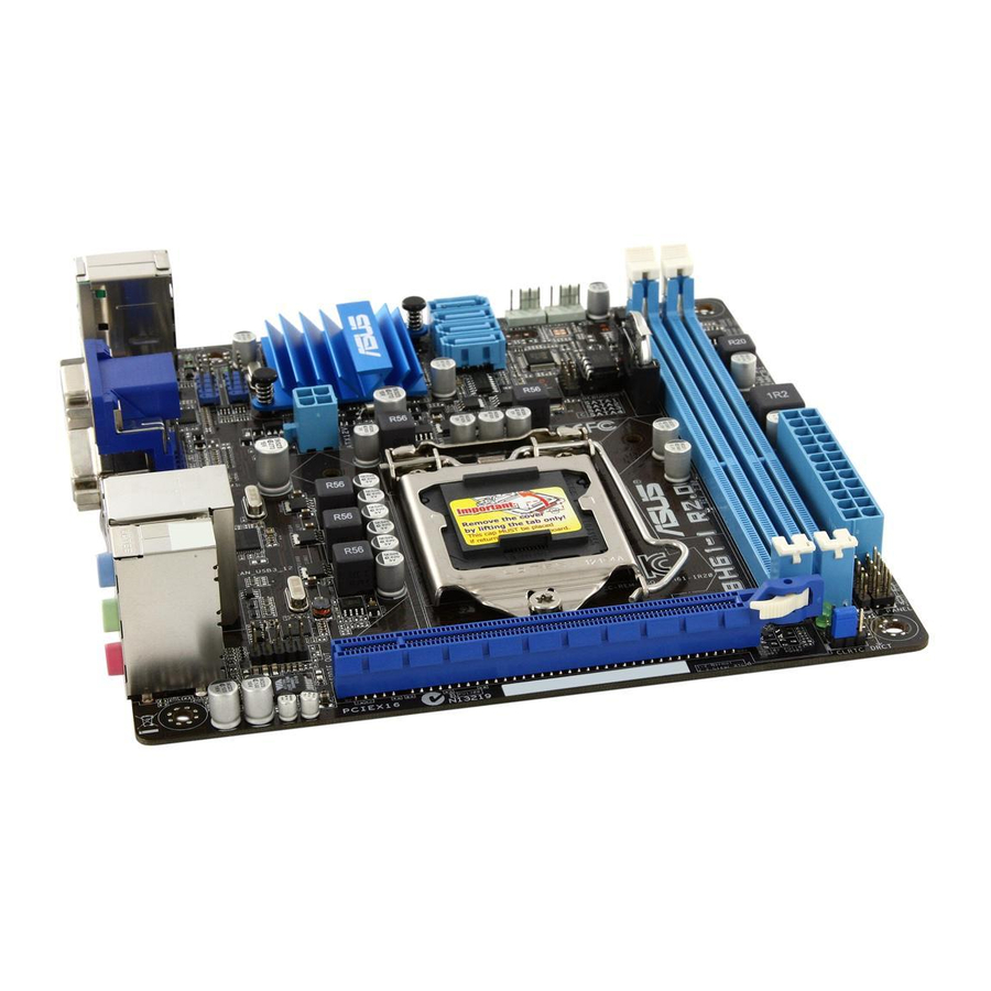
Page 18: Motherboard Layout
USB3_12 LAN_USB12 CHA_FAN Lithium Cell CMOS Power AUDIO 1042 P8H61/USB3 R2.0 8111F PCIEX16 PCIEX1_1 1083 Intel ® PCIEX1_2 Super PCI1 64Mb BIOS PCI2 CLRTC PCI3 SATA3G_4 SATA3G_3 SPDIF_OUT SB_PWR SATA3G_2 SATA3G_1 USB56 USB78 USB910 PANEL AAFP ASUS P8H61 R2.0 Series... - Page 19 19.8cm(7.8in) KBMS CPU_FAN DIGI+ ATX12V USB34 LAN_USB12 CHA_FAN Lithium Cell CMOS Power AUDIO P8H61 PLUS R2.0 8111F PCIEX16 PCIEX1_1 1083 Intel ® PCIEX1_2 Super PCI1 64Mb BIOS PCI2 CLRTC PCI3 SATA3G_4 SATA3G_3 SPDIF_OUT SB_PWR USB56 USB78 USB910 SATA3G_2 SATA3G_1 PANEL AAFP Chapter 1: Product introduction...
-
Page 20: Layout Contents
Digital audio connector (4-1 pin SPDIF_OUT) 1-29 ® DDR3 DIMM slots 1-16 Front panel audio connector (10-1 pin AAFP) 1-27 Clear RTC RAM (3-pin CLRTC) 1-25 Standby power LED (SB_PWR) Intel H61 Serial ATA 3.0Gb/s connectors 1-30 ® (7-pin SATA3G_1/2/3/4) 1-10 ASUS P8H61 R2.0 Series... -
Page 21: Central Processing Unit (Cpu)
Contact your retailer immediately if the PnP cap is missing, or if you see any damage to the PnP cap/socket contacts/motherboard components. ASUS will shoulder the cost of repair only if the damage is shipment/transit-related. • Keep the cap after installing the motherboard. ASUS will process Return Merchandise Authorization (RMA) requests only if the motherboard comes with the cap on the LGA1155 socket. - Page 22 CPU notches. The CPU fits in only one correct orientation. DO NOT force the CPU into the socket to prevent bending Gold the connectors on the socket and triangle damaging the CPU! mark Alignment keys 1-12 ASUS P8H61 R2.0 Series...
- Page 23 Apply some Thermal Interface Material to the exposed area of the CPU that the heatsink will be in contact with, ensuring that it is spread in an even thin layer. Some heatsinks come with pre- applied thermal paste. If so, skip this step.
-
Page 24: Installing The Cpu Heatsink And Fan
The type of CPU heatsink and fan assembly may differ, but the installation steps and functions should remain the same. The illustration above is for reference only. 1-14 ASUS P8H61 R2.0 Series... -
Page 25: Uninstalling The Cpu Heatsink And Fan
Connect the CPU fan cable to the connector on the motherboard labeled CPU_FAN. CPU_FAN P8H61/USB3 R2.0 P8H61/USB3 R2.0 CPU fan connector Do not forget to connect the CPU fan connector! Hardware monitoring errors can occur if you fail to plug this connector. 1.6.3 Uninstalling the CPU heatsink and fan To uninstall the CPU heatsink and fan:... -
Page 26: System Memory
DDR2 DIMM socket. DDR3 modules are developed for better performance with less power consumption. The figure illustrates the location of the DDR3 DIMM sockets: Channel Sockets Channel A DIMM_A1 Channel B DIMM_B1 P8H61/USB3 R2.0 P8H61/USB3 R2.0 240-pin DDR3 DIMM sockets 1-16 ASUS P8H61 R2.0 Series... -
Page 27: Memory Configurations
1.7.2 Memory configurations You may install 1GB, 2GB, 4GB, and 8GB unbuffered non-ECC DDR3 DIMMs into the DIMM sockets. • You may install varying memory sizes in Channel A and Channel B. The system maps the total size of the lower-sized channel for the dual-channel configuration. Any excess memory from the higher-sized channel is then mapped for single-channel operation. - Page 28 • G.SKILL F3-14900CL9Q-8GBXL(XMP) 8GB(2GB x 4) 9-9-9-24 1.6V • • KINGSTON KHX1866C9D3T1K3/3GX(XMP) 3GB(3 x 1GB) 1.65V • • KINGSTON KHX1866C9D3K4/16GX(XMP) 16GB(4GB x 4) DS 1.65V • • KINGSTON KHX1866C9D3T1K3/6GX(XMP) 6GB(3 x 2GB) 1.65V • • 1-18 ASUS P8H61 R2.0 Series...
- Page 29 DDR3-1600 MHz capability DIMM socket Chip support (Optional) Vendors Part No. Size Chip NO. Timing Voltage Brand 1 DIMM 2 DIMMs 3CCD-1509A A-DATA AM2U16BC2P1 A-DATA • • EL1126T A-DATA AD31600E001GM(O)U3K 3GB(3 x 1GB) 8-8-8-24 1.65V-1.85V • 3CCD-1509A A-DATA AM2U16BC4P2 DS A-DATA •...
- Page 30 OCZ3X13334GK(XMP) 4GB(2 x 2GB) DS - 7-7-7-20 1.75V • • OCZ3G1333LV6GK 6GB(3 x 2GB) DS - 9-9-9-20 1.65V • • OCZ3P1333LV6GK 6GB(3 x 2GB) DS - 7-7-7-20 1.65V • • (continued on the next page) 1-20 ASUS P8H61 R2.0 Series...
- Page 31 DDR3-1333 MHz capability DIMM socket support Chip (Optional) Vendors Part No. Size Chip NO. Timing Voltage Brand 1 DIMM 2 DIMMs OCZ3X1333LV6GK(XMP) 6GB(3 x 2GB) DS - 8-8-8-20 1.60V • • OCZ3G1333LV8GK 8GB(2x 4GB) DS - 9-9-9-20 1.65V • • OCZ3RPR1333C9LV8GK 8GB(2x 4GB) DS -...
- Page 32 • 1 DIMM: Supports one module inserted into either slot as single-channel memory configuration. • 2 DIMMs: Supports one pair of modules inserted into both the blue slots as one pair of dual-channel memory configuration. Visit the ASUS website at www.asus.com for the latest QVL. 1-22 ASUS P8H61 R2.0 Series...
-
Page 33: Installing A Dimm
1.7.3 Installing a DIMM Unplug the power supply before adding or removing DIMMs or other system components. Failure to do so can cause severe damage to both the motherboard and the components. Press the retaining clips outward to DIMM notch unlock a DIMM socket. -
Page 34: Expansion Slots
PCI Express specifications. 1.8.5 PCI Express 3.0/2.0 x16 slot This motherboard has a PCI Express 3.0/2.0 x16 slot that supports PCI Express 3.0/2.0 x16 graphic cards complying with the PCI Express specifications. 1-24 ASUS P8H61 R2.0 Series... -
Page 35: Jumpers
Jumpers Clear RTC RAM (3-pin CLRTC) This jumper allows you to clear the Real Time Clock (RTC) RAM in CMOS. You can clear the CMOS memory of date, time, and system setup parameters by erasing the CMOS RTC RAM data. The onboard button cell battery powers the RAM data in CMOS, which include system setup information such as system passwords. -
Page 36: Connectors
Mic In Bass/Center Bass/Center Lime (Front panel) – – – Side Speaker Out To configure an 8-channel audio output: Use a chassis with HD audio module in the front panel to support 8-channel audio output. 1-26 ASUS P8H61 R2.0 Series... -
Page 37: Internal Connectors
USB 2.0 ports 1 and 2. These two 4-pin Universal Serial Bus (USB) ports are for USB 2.0/1.1 devices. USB 2.0 ports 3 and 4 (P8H61 R2.0 and P8H61 PLUS R2.0 only). These two 4-pin Universal Serial Bus (USB) ports are for USB 2.0/1.1 devices. USB 3.0 ports 1 and 2 (P8H61/USB3 R2.0 only). - Page 38 The system may become unstable or may not boot up if the power is inadequate. • If you are uncertain about the minimum power supply requirement for your system, refer to the Recommended Power Supply Wattage Calculator at http://support.asus. com/PowerSupplyCalculator/PSCalculator.aspx?SLanguage=en-us for details. 1-28...
- Page 39 • The CPU_FAN connector supports a CPU fan of maximum 1A (12 W) fan power. • Only the 4-pin CPU fan supports the ASUS Fan Xpert feature. Digital audio connector (4-1 pin SPDIF_OUT) This connector is for an additional Sony/Philips Digital Interface (S/PDIF) port. Connect the S/PDIF Out module cable to this connector, then install the module to a slot opening at the back of the system chassis.
- Page 40 Configuration > SATA Mode Selection. 7, set the SATA Mode • When using hot-plug and NCQ on Windows Vista / Windows ® ® Selection item in the BIOS to [AHCI]. See section 2.5.3 SATA Configuration for details. 1-30 ASUS P8H61 R2.0 Series...
- Page 41 USB 2.0 connectors (10-1 pin USB56, USB78, USB910) These connectors are for USB 2.0 ports. Connect the USB module cable to any of these connectors, then install the module to a slot opening at the back of the system chassis. These USB connectors comply with USB 2.0 specification that supports up to 480 Mbps connection speed.
-
Page 42: System Panel Connector
ATX power button/soft-off button (2-pin PWRSW) This 2-pin connector is for the system power button. • Reset button (2-pin RESET) This 2-pin connector is for the chassis-mounted reset button for system reboot without turning off the system power. 1-32 ASUS P8H61 R2.0 Series... -
Page 43: Software Support
The contents of the Support DVD are subject to change at any time without notice. Visit the ASUS website at www.asus.com for updates. To run the Support DVD Place the Support DVD to the optical drive. - Page 44 1-34 ASUS P8H61 R2.0 Series...
-
Page 45: Chapter 2: Bios Information
® Updating the BIOS To update the BIOS: desktop, click Start > Programs > ASUS > AI Suite II > AI Suite II X.XX.XX to From the Windows ® launch the AI Suite II utility. The AI Suite II Quick Bar appears. -
Page 46: Asus Ez Flash 2
Insert the USB flash disk that contains the latest BIOS file to the USB port. Enter the Advanced Mode of the BIOS setup program. Go to the Tool menu to select ASUS EZ Flash 2 Utility and press <Enter> to enable it. -
Page 47: Asus Crashfree Bios 3 Utility
2.1.3 ASUS CrashFree BIOS 3 utility The ASUS CrashFree BIOS 3 is an auto recovery tool that allows you to restore the BIOS file when it fails or gets corrupted during the updating process. You can restore a corrupted BIOS file using the motherboard support DVD or a USB flash drive that contains the updated BIOS file. -
Page 48: Asus Bios Updater
Insert the USB flash drive with the latest BIOS file and BIOS Updater to the USB port. Boot your computer. When the ASUS Logo appears, press <F8> to show the BIOS Boot Device Select Menu. Insert the support DVD into the optical drive and select the optical drive as the boot device. -
Page 49: Updating The Bios File
Updating the BIOS file To update the BIOS file using BIOS Updater At the FreeDOS prompt, type bupdater /pc /g and press <Enter>. D:\>bupdater /pc /g The BIOS Updater screen appears as below. ASUSTek BIOS Updater for DOS V1.30 Current ROM Update ROM BOARD: P8H61/USB3 R2.0... -
Page 50: Bios Setup Program
• The BIOS setup screens shown in this section are for reference purposes only, and may not exactly match what you see on your screen. • Visit the ASUS website at www.asus.com to download the latest BIOS file for this motherboard. - Page 51 Default(F5) Power Saving mode Loads optimized default Selects the Advanced mode functions Normal mode ASUS Optimal mode Selects the boot device priority Selects the boot Displays the system properties of the device priority selected mode on the right hand side Displays the Advanced mode menus •...
-
Page 52: Advanced Mode
The Advanced Mode provides advanced options for experienced end-users to configure the BIOS settings. The figure below shows an example of the Advanced Mode. Refer to the following sections for the detailed configurations. To access the EZ Mode, click Exit, then select ASUS EZ Mode. Back button Menu items... -
Page 53: Menu Items
Menu items The highlighted item on the menu bar displays the specific items for that menu. For example, selecting Main shows the Main menu items. The other items (Ai Tweaker, Advanced, Monitor, Boot, Tool, and Exit) on the menu bar have their respective menu items. -
Page 54: Main Menu
RAM to clear the BIOS password. See section 1.9 Jumpers for information on how to erase the RTC RAM. • The Administrator or User Password items on top of the screen show the default Not Installed. After you set a password, these items show Installed. 2-10 ASUS P8H61 R2.0 Series... -
Page 55: Administrator Password
Administrator Password If you have set an administrator password, we recommend that you enter the administrator password for accessing the system. Otherwise, you might be able to see or change only selected fields in the BIOS setup program. To set an administrator password: Select the Administrator Password item and press <Enter>. -
Page 56: Ai Tweaker Menu
PCH Voltage 1.050V Auto F2: Previous Values F3: Shortcut CPU PLL Voltage Auto F5: Optimized Defaults F10: Save ESC: Exit CPU Spread Spectrum Auto F12: Print Screen Version 2.10.1208. Copyright (C) 2012 American Megatrends, Inc. 2-12 ASUS P8H61 R2.0 Series... -
Page 57: Ai Overclock Tuner [Auto]
2.4.1 Ai Overclock Tuner [Auto] Allows you to select the CPU overclocking options to achieve the desired CPU internal frequency. Select any of these preset overclocking configuration options: [Auto] Loads the optimal settings for the system. [Manual] Allows you to individually set overclocking parameters. [X.M.P.] If you install memory modules supporting the eXtreme Memory Profile (X.M.P.) Technology, choose this item to set the profiles supported by your... -
Page 58: Oc Tuner
Use the <+> and <-> keys to adjust the value. Short Duration Power Limit [Auto] Allows you to limit the turbo ratio’s long duration power. Use the <+> and <-> keys to adjust the value. 2-14 ASUS P8H61 R2.0 Series... -
Page 59: Digi+ Vrm
Primary Plane Current Limit [Auto] Maximum instantaneous current allowed at any given time for CPU cores Use <+> and <-> key to adjust the value at 0.125A increment. . . Secondary Plane Current Limit [Auto] Maximum instantaneous current allowed at any given time for Internal Graphics cores. Use <+>... -
Page 60: Cpu Voltage [Offset Mode]
• The values of the CPU Offset Voltage, CPU Manual Voltage, DRAM Voltage, VCCSA Voltage, and PCH Voltage items are labeled in different color, indicating the risk levels of high voltage settings. • The system may need better cooling system to work stably under high voltage settings. 2-16 ASUS P8H61 R2.0 Series... -
Page 61: Cpu Spread Spectrum [Auto]
2.4.13 CPU Spread Spectrum [Auto] [Auto] Automatic configuration. [Disabled] Enhances the BCLK overclocking ability. [Enabled] Sets to [Enabled] for EMI control. Advanced menu The Advanced menu items allow you to change the settings for the CPU and other system devices. Be cautious when changing the settings of the Advanced menu items. -
Page 62: Cpu Power Management Configuration
Enables or disables the C1E support function. This item should be enabled in order to enable the Enhanced Halt State. Configuration options: [Auto] [Enabled] [Disabled] CPU C3 Report [Auto] Allows you to disable or enable the CPU C3 report to OS. Configuration options: [Auto] [Enabled] [Disabled] 2-18 ASUS P8H61 R2.0 Series... -
Page 63: Pch Configuration
CPU C6 Report [Auto] Allows you to disable or enable the CPU C6 report to OS. Configuration options: [Auto] [Enabled] [Disabled] 2.5.2 PCH Configuration High Precision Timer [Enabled] Allows you to enable or disable the High Precision Event Timer. Configuration options: [Enabled] [Disabled] 2.5.3 SATA Configuration While entering Setup, the BIOS automatically detects the presence of SATA devices. -
Page 64: Usb Configuration
Sets the front panel audio connector (AAFP) mode to legacy AC’97 SPDIF Out Type [SPDIF] [SPDIF] Sets to [SPDIF] for SPDIF audio output. [HDMI] Sets to [HDMI] for HDMI audio output. Realtek LAN Controller [Enabled] [Enabled] Enables the Realtek LAN controller. [Disabled] Disables the controller. 2-20 ASUS P8H61 R2.0 Series... -
Page 65: Apm
Realtek PXE OPROM [Disabled] This item appears only when you set the previous item to [Enabled] and allows you to enable or disable the PXE OptionRom of the Realtek LAN controller. Configuration options: [Enabled] [Disabled] Asmedia USB 3.0 Controller [Enabled] (P8H61/USB3 R2.0 only) [Enabled] Enables the onboard USB 3.0 controller. -
Page 66: Network Stack
Ipv6 PXE Support [Enabled] This item appears only when you set the Network Stack item to [Enabled]. When this item is disabled, the IPV6 PXE boot option will not be created. Configuration options: [Disable Link] [Enabled] 2-22 ASUS P8H61 R2.0 Series... -
Page 67: Monitor Menu
Monitor menu The Monitor menu displays the system temperature/power status, and allows you to change the fan settings. UEFI BIOS Utility - Advanced Mode Exit Ai Tweaker Main Advanced Monitor Boot Tool CPU Temperature +45ºC / +113ºF +45ºC / +113ºF MB Temperature +34ºC / +93ºF CPU Fan Speed... -
Page 68: Cpu / Chassis Fan Speed
Use the <+> and <-> keys to adjust the minimum CPU fan duty cycle. The values range from 0% to 100%. When the CPU temperature is under 40ºC, the CPU fan will operate at the minimum duty cycle. 2-24 ASUS P8H61 R2.0 Series... -
Page 69: Chassis Q-Fan Control [Enabled]
2.6.5 Chassis Q-Fan Control [Enabled] [Disabled] Disables the Chassis Q-Fan control feature. [Enabled] Enables the Chassis Q-Fan control feature. Chassis Fan Speed Low Limit [200 RPM] This item appears only when you enable the Chassis Q-Fan Control feature and allows you to disable or set the chassis fan warning speed. -
Page 70: Boot Menu
[Disabled] Disables the full screen logo display feature. Set this item to [Enabled] to use the ASUS MyLogo 2™ feature. Post Report [5 sec] This item appears only when the Full Screen Logo item is set to [Disabled] and allows you to set the waiting time for the system to display the post report. -
Page 71: Option Rom Messages [Force Bios]
• To select the boot device during system startup, press <F8> when ASUS Logo appears. • To access Windows OS in Safe Mode, press <F8> after POST. -
Page 72: Tools Menu
> ASUS O.C. Profile 2.8.1 ASUS EZ Flash 2 Utility Allows you to run ASUS EZ Flash 2. Press [Enter] to launch the ASUS EZ Flash 2 screen. For more details, see section 2.1.2 ASUS EZ Flash 2. 2.8.2 ASUS SPD Information... -
Page 73: Exit Menu
Load Optimized Defaults Save Changes & Reset Discard Changes & Exit ASUS EZ Mode Launch EFI Shell from filesystem device Load Optimized Defaults This option allows you to load the default values for each of the parameters on the Setup menus. - Page 74 2-30 ASUS P8H61 R2.0 Series...
-
Page 75: Appendices
Appendices Notices Federal Communications Commission Statement This device complies with Part 15 of the FCC Rules. Operation is subject to the following two conditions: • This device may not cause harmful interference. • This device must accept any interference received including interference that may cause undesired operation. -
Page 76: Canadian Department Of Communications Statement
ASUS Recycling/Takeback Services ASUS recycling and takeback programs come from our commitment to the highest standards for protecting our environment. We believe in providing solutions for you to be able to responsibly recycle our products, batteries, other components as well as the packaging materials. Please go to http://csr.asus.com/english/Takeback.htm for the detailed recycling information in different... -
Page 77: Asus Contact Information
+1-510-739-3777 +1-510-608-4555 Web site usa.asus.com Technical Support Telephone +1-812-282-2787 Support fax +1-812-284-0883 Online support support.asus.com ASUS COMPUTER GmbH (Germany and Austria) Address Harkort Str. 21-23, D-40880 Ratingen, Germany +49-2102-959911 Web site www.asus.de Online contact www.asus.de/sales Technical Support Telephone +49-1805-010923* Support Fax...
Need help?
Do you have a question about the P8H61 USB3 R2.0 and is the answer not in the manual?
Questions and answers