Asus P8H77-V Manual
Hide thumbs
Also See for P8H77-V:
- User manual (1 page) ,
- Benutzerhandbuch (150 pages) ,
- User manual (90 pages)
Table of Contents
Advertisement
Quick Links
Advertisement
Table of Contents

Related Manuals for Asus P8H77-V


Summary of Contents for Asus P8H77-V
- Page 1 P8H77-V...
- Page 2 Product warranty or service will not be extended if: (1) the product is repaired, modified or altered, unless such repair, modification of alteration is authorized in writing by ASUS; or (2) the serial number of the product is defaced or missing.
-
Page 3: Table Of Contents
Contents Safety information ...................... vi About this guide ......................vii P8H77-V specifications summary ................ix Chapter 1: Product introduction Welcome! ...................... 1-1 Package contents ..................1-1 Special features ................... 1-2 1.3.1 Product highlights ................. 1-2 1.3.2 ASUS Exclusive Features ............. 1-3 1.3.3... - Page 4 Network Stack ................3-22 Monitor menu ..................... 3-23 Boot menu ....................3-26 Tools menu ....................3-28 3.8.1 ASUS EZ Flash 2 Utility .............. 3-28 3.8.2. ASUS O.C. Profile ............... 3-28 3.8.3 ASUS SPD Information ............... 3-29 Exit menu ....................3-30 3.10...
- Page 5 FAN Xpert ..................4-9 4.3.7 Probe II ..................4-10 4.3.8 Sensor Recorder ................. 4-11 4.3.9 USB 3.0 Boost ................4-12 4.3.10 ASUS Update ................4-13 4.3.11 MyLogo2 ..................4-14 4.3.12 High Definition Audio utility ..........4-16 ® RAID configurations .................. 4-17 4.4.1 RAID definitions ................
-
Page 6: Safety Information
Safety information Electrical safety • To prevent electrical shock hazard, disconnect the power cable from the electrical outlet before relocating the system. • When adding or removing devices to or from the system, ensure that the power cables for the devices are unplugged before the signal cables are connected. If possible, disconnect all power cables from the existing system before you add a device. -
Page 7: About This Guide
Where to find more information Refer to the following sources for additional information and for product and software updates. ASUS websites The ASUS website provides updated information on ASUS hardware and software products. Refer to the ASUS contact information. Optional documentation Your product package may include optional documentation, such as warranty flyers, that may have been added by your dealer. -
Page 8: Conventions Used In This Guide
Conventions used in this guide To ensure that you perform certain tasks properly, take note of the following symbols used throughout this manual. DANGER/WARNING: Information to prevent injury to yourself when trying to complete a task. CAUTION: Information to prevent damage to the components when trying to complete a task. -
Page 9: P8H77-V Specifications Summary
** Due to the CPU behavior, DDR3 2133/1866 MHz memory module will run at DDR3 2000/1800 MHz frequency as default. *** Refer to www.asus.com for the latest Memory QVL (Qualified Vendors List). **** When you install a total memory of 4GB capacity or more,... - Page 10 ® UASP standard only supports Windows ® ASUS DIGI+ VRM ASUS unique features - ASUS DIGI+ VRM: Digital Power Design for the CPU and iGPU - ASUS 6+1+2 Phase Power Design ASUS Protect 3.0 - EPU - ASUS Anti-Surge Protection...
- Page 11 BIOS features 64 Mb Flash ROM, UEFI AMI BIOS, PnP, DMI 2.0, WfM 2.0, SM BIOS 2.6, ACPI 2.0a, Multi-language BIOS, ASUS EZ Flash 2, ASUS CrashFree BIOS 3, F12 PrintScreen Function, F3 Shortcut function, and ASUS DRAM SPD (Serial Presence Detect)
-
Page 13: Chapter 1: Product Introduction
® The motherboard delivers a host of new features and latest technologies, making it another standout in the long line of ASUS quality motherboards! Before you start installing the motherboard, and hardware devices on it, check the items in your package with the list below. -
Page 14: Special Features
Special features 1.3.1 Product highlights LGA1155 socket for Intel 3rd/2nd Generation Core™ i7 / Core™ i5 / ® Core™ i3 / Pentium / Celeron Processors ® ® This motherboard supports the Intel 3rd/2nd generation Core™ i7/i5/i3/Pentium /Celeron ® ® ® processors in the LGA1155 package, with iGPU, memory, and PCI Express controllers integrated to support onboard graphics out with dedicated chipsets, 2-channel (4 DIMMs) DDR3 memory, and 16 PCI Express 3.0/2.0 lanes. -
Page 15: Asus Exclusive Features
Complete USB 3.0 Integration Double USB Access, Double Convenience ASUS facilitates the strategic USB 3.0 accessibility for both the front and rear panel – 4 USB 3.0 ports in total. Experience the latest plug & play connectivity at speeds up to 10 times faster than USB 2.0. -
Page 16: Gpu Boost
ASUS TurboV Feel the adrenaline rush of real-time OC-now a reality with the ASUS TurboV. This easy OC tool allows you to overclock without exiting or rebooting the OS; and its user-friendly interface makes overclock with just a few clicks away. Moreover, the ASUS OC profiles in TurboV provides the best O.C. -
Page 17: Asus Quiet Thermal Solution
DVD or USB flash disk that contains the latest BIOS file. ASUS EZ-Flash 2 ASUS EZ Flash 2 is a user-friendly utility that allows you to update the BIOS without using a bootable floppy disk or an OS-based utility. -
Page 18: Other Special Features
ASUS Q-Slot ASUS Q-Slot is designed to speed up and simplify the DIY process to enhance your DIY experience. 1.3.5 Other special features LucidLogix Virtu MVP LucidLogix Virtu MVP featuring HyperFormance™ Technology boosts your PCIe graphics card up to 60% beyond its original performance. Designed for Intel processor graphics and ®... -
Page 19: Chapter 2: Hardware Information
Before you install or remove any component, ensure that the ATX power supply is switched off or the power cord is detached from the power supply. Failure to do so may cause severe damage to the motherboard, peripherals, or components. ASUS P8H77-V... -
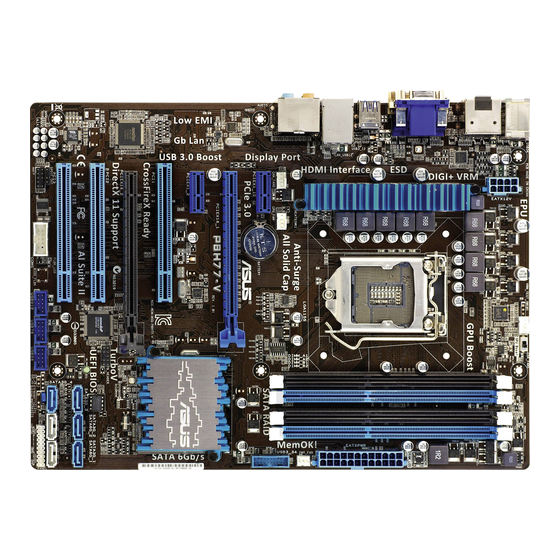
Page 20: Motherboard Overview
DIGI +VRM SPDIF_O EATX12V _HDMI MemOK! DRAM_LED USB3_12 LAN1_USB12 AUDIO CPU_FAN CHA_FAN2 PWR_FAN PCIEX1_1 Lithium Cell CMOS Power USB3_34 PCIEX16_1 8161 P8H77-V PCIEX1_2 Intel ® PCI1 Super PCIEX16_2 PCI2 64Mb 1083 BIOS SATA3G_3 SATA3G_2 SATA3G_1 VT1708S SB_PWR PCI3 SATA3G_4 SATA6G_2... -
Page 21: Layout Contents
2-26 Clear RTC RAM (3-pin CLRTC) 2-15 USB 2.0 connectors (10-1 pin USB56, USB78, USB910) 2-21 Serial port connector (10-1 pin COM1) 2-22 Front panel audio connector (10-1 pin AAFP) 2-24 Digital audio connector (4-1 pin SPDIF_OUT) 2-22 ASUS P8H77-V... -
Page 22: Central Processing Unit (Cpu)
Contact your retailer immediately if the PnP cap is missing, or if you see any damage to the PnP cap/socket contacts/motherboard components. ASUS will shoulder the cost of repair only if the damage is shipment/ transit-related. -
Page 23: System Memory
The motherboard comes with four Double Data Rate 3 (DDR3) Dual Inline Memory Modules (DIMM) slots. A DDR3 module is notched differently from a DDR or DDR2 module. DO NOT install a DDR or DDR2 memory module to the DDR3 slot. P8H77-V P8H77-V 240-pin DDR3 DIMM sockets Recommended memory configurations ASUS P8H77-V... -
Page 24: Memory Configurations
• For system stability, use a more efficient memory cooling system to support a full memory load (4 DIMMs) or overclocking condition. P8H77-V Motherboard Qualified Vendors Lists (QVL) DDR3 2400 MHz (O.C.) capability DIMM socket support (Optional) Chip... - Page 25 P8H77-V Motherboard Qualified Vendors Lists (QVL) DDR3 2250 MHz (O.C.) capability DIMM socket support Chip (Optional) Vendors Part No. Size SS/DS Chip NO. Timing Voltage Brand 1 DIMM 2 DIMMs 4 DIMMs Kingston KHX2250C9D3T1K2/4GX(XMP) 4GB(2 x 2GB) DS 1.65V •...
- Page 26 P8H77-V Motherboard Qualified Vendors Lists (QVL) DDR3 1866 MHz (O.C.) capability DIMM socket support Chip (Optional) Vendors Part No. Size SS/DS Chip NO. Timing Voltage Brand 1 DIMM 2 DIMMs 4 DIMMs Corsair CMT4GX3M2A1866C9(XMP) 4GB(2 x 2GB) 9-9-9-24 1.65V •...
- Page 27 P8H77-V Motherboard Qualified Vendors Lists (QVL) DDR3 1600 MHz capability (continued) DIMM socket support Chip (Optional) Vendors Part No. Size Chip NO. Timing Voltage Brand 1 DIMM 2 DIMMs 4 DIMMs Kingston KHX1600C7D3K2/4GX(XMP) 4GB(2 x 2GB) DS - 1.65V •...
- Page 28 P8H77-V Motherboard Qualified Vendors Lists (QVL) DDR3 1333 MHz capability (continued) DIMM socket support Chip (Optional) Vendors Part No. Size Chip NO. Timing Voltage Brand 1 DIMM 2 DIMMs 4 DIMMs Corsair CMD8GX3M4A1333C7 8GB(4 x 2GB) DS - 7-7-7-20 1.60V •...
- Page 29 P8H77-V Motherboard Qualified Vendors Lists (QVL) DDR3 1333 MHz capability (continued) DIMM socket support (Optional) Vendors Part No. Size Chip Brand Chip NO. Timing Voltage 1 DIMM 2 DIMMs 4 DIMMs Kingston KVR1333D3N9/4G-SP DS Kingston D2568JENCPGD9U - 1.5V • •...
- Page 30 A2 and B2 for better compatibility. • 4 DIMMs: Supports four (4) modules inserted into both the blue and black slots as two pairs of Dual-channel memory configuration. Visit the ASUS website for the latest QVL. Chapter 2: Hardware information 2-12...
-
Page 31: Expansion Slots
PCIe 2.0 x16_2 slot (at x4 mode, compatible with PCIe x1 and x4 devices) PCI slot 2 PCI slot 3 PCI Express operating mode VGA configuration PCIe 3.0 x16_1 PCIe 2.0 x16_2 Single VGA/PCIe card x16 (Recommend for single VGA) Dual VGA/PCIe card ASUS P8H77-V 2-13... -
Page 32: Irq Assignments For This Motherboard
• In single VGA card mode, use the PCIe 3.0 x16_1 slot (blue) for a PCI Express x16 graphics card to get better performance. • We recommend that you provide sufficient power when running CrossFireX™ mode. Refer to page 2-25 for details. •... -
Page 33: Jumper
CLRTC Normal Clear RTC (Default) P8H77-V Clear RTC RAM To erase the RTC RAM: Turn OFF the computer and unplug the power cord. Move the jumper cap from pins 1-2 (default) to pins 2-3. Keep the cap on pins 2-3 for about 5-10 seconds, then move the cap back to pins 1-2. -
Page 34: Onboard Switches
BIOS default settings. A message will appear during POST reminding you that the BIOS has been restored to its default settings. • We recommend that you download and update to the latest BIOS version from the ASUS website at www.asus.com after using the MemOK! function. Chapter 2: Hardware information 2-16... -
Page 35: Onboard Leds
GPU Boost switch This switch allows you to enable or disable the GPU Boost function. GPU Boost P8H77-V P8H77-V GPU Boost switch 2.2.7 Onboard LEDs Standby Power LED The motherboard comes with a standby power LED that lights up to indicate that the system is ON, in sleep mode, or in soft-off mode. - Page 36 This user-friendly design provides an intuitional way to locate the root problem within a second. DRAM LED P8H77-V P8H77-V DRAM LED GPU Boost LED The GPU Boost LED lights when the GPU Boost switch is turned to Enable. GPU_LED P8H77-V P8H77-V GPU Boost LED Chapter 2: Hardware information 2-18...
-
Page 37: Internal Connectors
® ® chipset. P8H77-V P8H77-V P8H77-V Intel SATA 6.0Gb/s connectors ® • These connectors are set to [IDE] by default. If you intend to create a Serial ATA RAID set using these connectors, set the SATA Mode Selection item in the BIOS to [RAID]. - Page 38 ® Rapid Storage Technology through the onboard Intel ® chipset. P8H77-V P8H77-V Intel ® SATA 3.0Gb/s connectors • These connectors are set to [IDE] by default. If you intend to create a Serial ATA RAID set using these connectors, set the SATA Mode Selection item in the BIOS to [RAID].
- Page 39 USB 3.0 connector, you can have a front panel USB 3.0 solution. USB3_34 P8H77-V P8H77-V USB3.0 front panel connector • The USB 3.0 module is purchased separately. • Due to Intel limitations, the USB3_34 only supports Windows 7 operating system.
- Page 40 This connector is for a serial (COM) port. Connect the serial port module cable to this connector, then install the module to a slot opening at the back of the system chassis. COM1 PIN 1 P8H77-V P8H77-V Serial port (COM1) connector The COM module is purchased separately. Chapter 2: Hardware information 2-22...
- Page 41 • The CPU_FAN connector supports the CPU fan of maximum 1A (12 W) fan power. • Only the CPU_FAN, CHA_FAN1 and CHA_FAN2 connectors support the ASUS FAN Xpert feature. • If you install two VGA cards, we recommend that you plug the rear chassis fan cable to the motherboard connector labeled CHA_FAN1 or CHA_FAN2 for better thermal environment.
-
Page 42: Front Panel Audio Connector
P8H77-V HD-audio-compliant Legacy AC’97 pin definition compliant definition P8H77-V Front panel audio connector • We recommend that you connect a high-definition front panel audio module to this connector to avail of the motherboard’s high-definition audio capability. • If you want to connect a high-definition front panel audio module to this connector, If you want to connect a high-definition front panel audio module to this connector, set the Front Panel Type item in the BIOS setup to [HD];... - Page 43 If you want to use two high-end PCI Express x16 cards, use a PSU with 1000W power or above to ensure the system stability. • If you are uncertain about the minimum power supply requirement for your system, refer to the Recommended Power Supply Wattage Calculator at http://support.asus. com/PowerSupplyCalculator/PSCalculator.aspx?SLanguage=en-us for details. ASUS P8H77-V 2-25...
-
Page 44: System Panel Connector
+IDE_LED PWRSW RESET * Requires an ATX power supply P8H77-V System panel connector • System power LED (2-pin PLED) This 2-pin connector is for the system power LED. Connect the chassis power LED cable to this connector. The system power LED lights up when you turn on the system power, and blinks when the system is in sleep mode. -
Page 45: Building Your Computer System
Intel LGA 1155 CPU Intel LGA 1155 compatible CPU Fan DIMM SATA hard disk drive SATA optical disc drive (optional) Graphics card (optional) The tools and components in the table above are not included in the motherboard package. ASUS P8H77-V 2-27... -
Page 46: Cpu Installation
2.3.2 CPU installation The LGA1156 CPU is incompatible with the LGA1155 socket. DO NOT install a LGA1156 CPU on the LGA1155 socket. Chapter 2: Hardware information 2-28... - Page 47 ASUS P8H77-V 2-29...
-
Page 48: Cpu Heatsink And Fan Assembly Installation
2.3.3 CPU heatsink and fan assembly installation Apply the Thermal Interface Material to the CPU heatsink and CPU before you install the heatsink and fan if necessary. To install the CPU heatsink and fan assembly Chapter 2: Hardware information 2-30... - Page 49 To uninstall the CPU heatsink and fan assembly ASUS P8H77-V 2-31...
-
Page 50: Dimm Installation
2.3.4 DIMM installation To remove a DIMM Chapter 2: Hardware information 2-32... -
Page 51: Motherboard Installation
2.3.5 Motherboard installation The diagrams in this section are for reference only. The motherboard layout may vary with models, but the installation steps remain the same. ASUS P8H77-V 2-33... - Page 52 P8H77-V DO NOT overtighten the screws! Doing so can damage the motherboard. Chapter 2: Hardware information 2-34...
-
Page 53: Atx Power Connection
2.3.6 ATX Power connection ASUS P8H77-V 2-35... -
Page 54: Sata Device Connection
2.3.7 SATA device connection Chapter 2: Hardware information 2-36... -
Page 55: Front I/O Connector
2.3.8 Front I/O Connector To install the system panel connector To install USB 2.0 Connector To install front panel audio connector AAFP USB 2.0 To install USB 3.0 Connector USB 3.0 ASUS P8H77-V 2-37... -
Page 56: Expension Card Installation
2.3.9 Expension Card installation To install PCIe x16 cards To install PCIe x1 cards To install PCI cards Chapter 2: Hardware information 2-38... -
Page 57: Rear Panel Connection
7. DisplayPort 2. Optical S/PDIF output port 8. DVI-D port 3. D-Sub port 9. Intel USB 3.0 ports 1 and 2*, support ASUS USB 3.0 Boost Turbo Mode. 4. Atheros LAN (RJ-45) port** ® 5. USB 2.0 ports 3 and 4 10. - Page 58 • DO NOT connect a keyboard / mouse to any USB 3.0 port when installing Windows ® operating system. • Due to USB 3.0 controller limitation, USB 3.0 devices can only be used under Windows OS environment and after the USB 3.0 driver installation. ®...
-
Page 59: Audio I/O Connections
2.3.11 Audio I/O connections Audio I/O ports Connect to Headphone and Mic Connect to Stereo Speakers Connect to 2.1 channel Speakers ASUS P8H77-V 2-41... - Page 60 Connect to 4.1 channel Speakers Connect to 5.1 channel Speakers Connect to 7.1 channel Speakers Chapter 2: Hardware information 2-42...
-
Page 61: Starting Up For The First Time
While the system is ON, pressing the power switch for less than four seconds puts the system on sleep mode or soft-off mode, depending on the BIOS setting. Pressing the power switch for more than four seconds lets the system enter the soft-off mode regardless of the BIOS setting. ASUS P8H77-V 2-43... - Page 62 Chapter 2: Hardware information 2-44...
-
Page 63: Chapter 3: Bios Setup
BIOS setup Knowing BIOS The new ASUS UEFI BIOS is a Unified Extensible Interface that complies with UEFI architecture, offering a user-friendly interface that goes beyond the traditional keyboard- only BIOS controls to enable a more flexible and convenient mouse input. Users can easily navigate the new UEFI BIOS with the same smoothness as their operating system. -
Page 64: Ez Mode
CPU/chassis/power fan speed Selects the Advanced Loads optimized default Power Saving mode mode functions Normal mode ASUS Optimal mode Displays the system properties of the selected mode on the right Selects the boot device priority Selects the boot device priority hand side Displays the Advanced mode •... -
Page 65: Advanced Mode
The Advanced Mode provides advanced options for experienced end-users to configure the BIOS settings. The figure below shows an example of the Advanced Mode. Refer to the following sections for the detailed configurations. To access the EZ Mode, click Exit, then select ASUS EZ Mode. Back button Menu items... -
Page 66: Menu Items
Menu items The highlighted item on the menu bar displays the specific items for that menu. For example, selecting Main shows the Main menu items. The other items (Ai Tweaker, Advanced, Monitor, Boot, Tool, and Exit) on the menu bar have their respective menu items. -
Page 67: Main Menu
RAM to clear the BIOS password. See section 2.2.5 Jumper for information on how to erase the RTC RAM. The Administrator or User Password items on top of the screen show the default • Not Installed. After you set a password, these items show Installed. ASUS P8H77-V... -
Page 68: Administrator Password
Administrator Password If you have set an administrator password, we recommend that you enter the administrator password for accessing the system. Otherwise, you might be able to see or change only selected fields in the BIOS setup program. To set an administrator password: Select the Administrator Password item and press <Enter>. -
Page 69: Ai Tweaker Menu
PCH Voltage 1.050V Auto +/-: Change Opt. F1: General Help VCCSA Voltage Auto F2: Previous Values F5: Optimized Defaults CPU PLL Voltage Auto F10: Save ESC: Exit F12: Print Screen Version 2.10.1208. Copyright (C) 2011 American Megatrends, Inc. ASUS P8H77-V... -
Page 70: Dram Timing Control
Ai Overclock Tuner [Auto] Allows you to select the CPU overclocking options to achieve the desired CPU internal frequency. Select any of these preset overclocking configuration options: [Auto] Loads the optimal settings for the system. [Manual] Allows you to individually set overclocking parameters. BCLK/PEG Frequency [XXX] Appears when you set the Ai Overclock Tuner item to [Manual] and allows you to adjust the CPU and VGA frequency to enhance the system performance. - Page 71 Use <+> and <-> key to adjust the value at 0.125A increment. . . Secondary Plane Current Limit [Auto] Maximum instantaneous current allowed at any given time for Internal Graphics cores. Use <+> and <-> key to adjust the value at 0.125A increment. ASUS P8H77-V...
- Page 72 DIGI+ VRM CPU Load-Line Calibration [Auto] Load-line is defined by Intel VRM specifications, and affects CPU voltage. The CPU working voltage will decrease proportionally to CPU loading. Higher value gets a higher voltage, and a better overclocking performance, but increases the CPU and VRM thermal conditions. This item allows you to adjust the voltage range from the following percentages to boost the system performance: 0% (Regular), 25% (Medium), 50% (High), 75% (Ultra High) and 100% (Extreme).
-
Page 73: Cpu Offset Mode Sign
Allows you to set the DRAM voltage. The values range from 1.185V to 2.135V with a 0.005V interval. According to Intel CPU spec, DIMMs with voltage requirement over 1.65V may damage the CPU permanently. We recommend you install the DIMMs with the voltage requirement below 1.65V. ASUS P8H77-V 3-11... - Page 74 VCCIO Voltage [Auto] Allows you to set the VCCIO voltage. The values range from 0.7350V to 1.6850V with a 0.005V interval. PCH Voltage [Auto] Allows you to set the Platform Controller Hub volage. The values range from 0.7350V to 1.6850V with a 0.005V interval. VCCSA Voltage [Auto] Allows you to set the VCCSA voltage.
-
Page 75: Advanced Menu
> Network Stack →←: Select Screen ↑↓: Select Item Enter: Select +/-: Change Opt. F1: General Help F2: Previous Values F5: Optimized Defaults F10: Save ESC: Exit F12: Print Screen Version 2.10.1208. Copyright (C) 2011 American Megatrends, Inc. ASUS P8H77-V 3-13... -
Page 76: Cpu Configuration
3.5.1 CPU Configuration The items in this menu show the CPU-related information that the BIOS automatically detects. The items shown in this screen may be different due to the CPU you installed. UEFI BIOS Utility - Advanced Mode Exit Ai Tweaker Main Advanced Monitor... -
Page 77: Cpu Power Management Configuration
Allows processor cores to run faster than marked frequency in specific condition. [Disabled] Disables this function. CPU C1E [Auto] Enables or disables the C1E support function. This item should be enabled in order to enable the Enhanced Halt State. Configuration options: [Auto] [Enabled] [Disabled] ASUS P8H77-V 3-15... -
Page 78: Pch Configuration
CPU C3 Report [Auto] Allows you to disable or enable the CPU C3 report to OS. Configuration options: [Auto] [Enabled] [Disabled] CPU C6 Report [Auto] Allows you to disable or enable the CPU C6 report to OS. Configuration options: [Auto] you to disable or enable the CPU C6 report to OS. -
Page 79: Sata Configuration
POST. Configuration options: [Enabled] [Disabled] Hot Plug [Disabled] These items appear only when you set the SATA mode item to [AHCI] or [RAID], and allow you to enable/disable SATA Hot Plug Support. Configuration options: [Disabled] [Enabled] ASUS P8H77-V 3-17... -
Page 80: System Agent Configuration
3.5.4 System Agent Configuration UEFI BIOS Utility - Advanced Mode Main Ai Tweaker Advanced Monitor Boot Tool Back Advanced\ System Agent Configuration > Enable or disable memory remap above System Agent Bridge Name SandyBridge Memory Remap Feature Enabled > Graphics Configuration >... -
Page 81: Usb Configuration
Allows you to select an operation mode for the Intel xHCI controller. Configuration options: [Smart Auto] [Auto] [Enabled] [Disabled] EHCI Hand-off [Disabled] [Enabled] Enables the support for operating systems without an EHCI hand-off feature. [Disabled] Disables the function. ASUS P8H77-V 3-19... -
Page 82: Onboard Devices Configuration
3.5.6 Onboard Devices Configuration UEFI BIOS Utility - Advanced Mode Exit Main Ai Tweaker Advanced Monitor Boot Tool Back Advanced\ Onboard Devices Configuration > Enabled/Disabled Azalia HD Audio HD Audio controller Enabled Front Panel Type Atheros Lan Enabled Atheros Rom Disabled >... -
Page 83: Apm
Power On By PS/2 Mouse [Disabled] [Disabled] Disables the Power On by a PS/2 mouse. [Enabled] Enables the Power On by a PS/2 mouse. This feature requires an ATX power supply that provides at least 1A on the +5VSB lead. ASUS P8H77-V 3-21... -
Page 84: Network Stack
Power On By PCIE/PCI [Disabled] [Disabled] Disables the PCIE/PCI devices to generate a wake-on-LAN feature of the Intel/Realtek LAN device. [Enabled] Enables the PCIE/PCI devices to generate a wake-on-LAN feature of the Intel/Realtek LAN device. Power On By Ring [Disabled] [Disabled] Disables Ring to generate a wake event. -
Page 85: Monitor Menu
The onboard hardware monitor automatically detects and displays the CPU, chassis, and power fan speed in rotations per minute (RPM). If the fan is not connected to the motherboard, the field shows N/A. Select Ignore if you do not wish to display the detected speed. ASUS P8H77-V 3-23... - Page 86 CPU Q-Fan Control [Enabled] [Disabled] Disables the CPU Q-Fan control feature. [Enabled] Enables the CPU Q-Fan control feature. CPU Fan Speed Low Limit [600 RPM] This item appears only when you enable the CPU Q-Fan Control feature and allows you to disable or set the CPU fan warning speed.
- Page 87 The onboard hardware monitor automatically detects the voltage output through the onboard voltage regulators. Select Ignore if you do not want to detect this item. Anti Surge Support [Enabled] This item allows you to enable or disable the Anti Surge function. Configuration options: [Disabled] [Enabled] ASUS P8H77-V 3-25...
-
Page 88: Boot Menu
[Disabled] Disables the full screen logo display feature. Set this item to [Enabled] to use the ASUS MyLogo 2™ feature. Post Report [5 sec] This item appears only when the Full Screen Logo item is set to [Disabled] and allows you to set the waiting time for the system to display the post report. -
Page 89: Boot Option Priorities
• To select the boot device during system startup, press <F8> when ASUS Logo appears. • To access Windows OS in Safe Mode, press <F8> after POST. -
Page 90: Tools Menu
> ASUS SPD Information 3.8.1 ASUS EZ Flash 2 Utility Allows you to run ASUS EZ Flash 2. Press [Enter] to launch the ASUS EZ Flash 2 screen. For more details, refer to section 3.10.2 ASUS EZ Flash 2 utility. 3.8.2. -
Page 91: Asus Spd Information
We recommend that you update the BIOS file only coming from the same memory/CPU configuration and BIOS version. 3.8.3 ASUS SPD Information DIMM Slot # [Slot 1] Displays the Serial Presence Detect (SPD) information of the DIMM module installed on the selected slot. -
Page 92: Exit Menu
Load Optimized Defaults Save Changes & Reset Discard Changes & Exit ASUS EZ Mode Launch EFI Shell from filesystem device Load Optimized Defaults This option allows you to load the default values for each of the parameters on the Setup menus. -
Page 93: Updating Bios
BIOS in the future. Copy the original motherboard BIOS using the ASUS Update or BIOS Updater utilities. 3.10.1 ASUS Update utility The ASUS Update is a utility that allows you to manage, save, and update the motherboard BIOS in Windows environment. The ASUS Update utility allows you to: ®... -
Page 94: Updating The Bios Through The Internet
Updating the BIOS through the Internet To update the BIOS through the Internet: From the ASUS Update screen, select Update BIOS from Internet, and then click Next. Select the ASUS FTP site nearest you to avoid network traffic. If you want to enable the BIOS... -
Page 95: Updating The Bios Through A Bios File
The screenshots in this section are for reference only. The actual BIOS information vary by models. • Refer to the software manual in the support DVD or visit the ASUS website at www.asus.com for detailed software configuration. ASUS P8H77-V 3-33... -
Page 96: Asus Ez Flash 2 Utility
3.10.2 ASUS EZ Flash 2 utility The ASUS EZ Flash 2 feature allows you to update the BIOS without having to use a bootable floppy disk or an OS-based utility. Before you start using this utility, download the latest BIOS from the ASUS website at www.asus.com. -
Page 97: Asus Crashfree Bios 3 Utility
The BIOS file in the motherboard support DVD may be older than the BIOS file published on the ASUS official website. If you want to use the newer BIOS file, download the file at support.asus.com and save it to a USB flash drive. -
Page 98: Asus Bios Updater
3.10.4 ASUS BIOS Updater The ASUS BIOS Updater allows you to update BIOS in DOS environment. This utility also allows you to copy the current BIOS file that you can use as a backup when the BIOS fails or gets corrupted during the updating process. -
Page 99: Updating The Bios File
Select the Load Optimized Defaults item under the Exit BIOS menu. See Chaper 3 of your motherboard user manual for details. • Ensure to connect all SATA hard disk drives after updating the BIOS file if you have disconnected them. ASUS P8H77-V 3-37... - Page 100 Chapter 3: BIOS setup 3-38...
-
Page 101: Chapter 4: Software Support
The contents of the support DVD are subject to change at any time without notice. Visit the ASUS website at www.asus.com for updates. 4.2.1 Running the support DVD Place the support DVD into the optical drive. -
Page 102: Obtaining The Software Manuals
The software manual files are in Portable Document Format (PDF). Install the Adobe ® Acrobat Reader from the Utilities menu before opening the files. ® Click the Manual tab. Click ASUS Motherboard Utility Guide from the manual list on the left. The Manual folder of the support DVD appears. Double-click the folder of your selected software. -
Page 103: Software Information
4.3.1 AI Suite II AI Suite II is an all-in-one interface that integrates several ASUS utilities and allows users to launch and operate these utilities simultaneously. Installing AI Suite II To install AI Suite II on your computer Place the support DVD to the optical drive. -
Page 104: Auto Tuning
4.3.2 Auto Tuning Auto Tuning is an intelligent tool that overclocks your system to achieve a total system level up using TurboV. Even O.C. beginners can achieve extreme yet stable overclocking results with Auto Tuning! • The overclocking result varies with the CPU model and the system configuration. •... -
Page 105: Digi+ Vrm
The actual performance boost may vary depending on your CPU specification. • Do not remove the thermal module. The thermal conditions should be monitored. Refer to the software manual in the support DVD or visit the ASUS website at www.asus.com for detailed software configuration. ASUS P8H77-V... -
Page 106: Turbov Evo
After installing AI Suite II from the motherboard support DVD, launch TurboV EVO by clicking Tool > TurboV EVO on the AI Suite II main menu bar. Refer to the software manual in the support DVD or visit the ASUS website at www.asus.com for detailed software configuration. - Page 107 DVD. • For system stability, all changes made in ASUS GPU Boost will not be saved to the BIOS settings and will not be kept on the next system boot. Use the Save Profile function to save your customized overclocking settings and manually load the profile after Windows starts.
-
Page 108: Epu
Select From the Last Reset to show the total CO2 that has been reduced. *• • Refer to the software manual in the support DVD or visit the ASUS website at www.asus.com for detailed software configuration. Chapter 4: Software support... -
Page 109: Fan Xpert
Turbo: maximizes the fan speed for the best cooling effect. • User: Allows you to configure the CPU fan profile under certain limitations. • Refer to the software manual in the support DVD or visit the ASUS website at www.asus.com for detailed software configuration. ASUS P8H77-V... -
Page 110: Probe Ii
Applies your changes configuration Loads the default threshold Loads your saved values for each sensor configuration Refer to the software manual in the support DVD or visit the ASUS website at www.asus.com for detailed software configuration. Chapter 4: Software support 4-10... -
Page 111: Sensor Recorder
To track the recorded contents, set Type / Date / Select display items to display the history details. Click on Monitor > Sensor on the AI Suite II main menu bar and a highlight of the system statuses will appear on the right panel. ASUS P8H77-V 4-11... -
Page 112: Usb 3.0 Boost
4.3.9 USB 3.0 Boost The ASUS exclusive USB 3.0 Boost provides speed boost for USB 3.0 devices and the up-to-date support of USB Attached SCSI Protocol (UASP). With USB 3.0 Boost, you can accelerate the transfer speed of your USB 3.0 devices with ease. -
Page 113: Asus Update
4.3.10 ASUS Update ASUS Update lays out the options for updating BIOS on your system. Update BIOS utility on your system or simply save the utility for later use just by following the directions on this convenient updating feature. Launching ASUS Update After installing AI Suite II from the motherboard support DVD, launch ASUS Update by clicking Update >... -
Page 114: Mylogo2
Power-On-Self-Tests (POST). Personalize your computer from the very beginning! Launching ASUS Update After installing AI Suite II from the motherboard support DVD, launch MyLogo by clicking Update > MyLogo on the AI Suite II main menu bar. - Page 115 Then at Picture File, Browse to select the desired image for boot logo. Click Next. Follow steps 2~5 in Change the BIOS boot logo of my motherboard to complete logo update. The fullscreen logo application in BIOS utility must be enabled for MyLogo to take effect. ASUS P8H77-V 4-15...
-
Page 116: Via ® High Definition Audio Utility
VIA HD Audio Deck for Windows ® Display panel and volume control Configuration Minimize button options Control settings window Refer to the software manual in the support DVD or visit the ASUS website at www.asus.com for detailed software configuration. Chapter 4: Software support 4-16... -
Page 117: Raid Configurations
With the RAID 10 configuration you get all the benefits of both RAID 0 and RAID 1 configurations. Use four new hard disk drives or use an existing drive and three new drives for this setup. ASUS P8H77-V 4-17... -
Page 118: Installing Serial Ata Hard Disks
4.4.2 Installing Serial ATA hard disks The motherboard supports Serial ATA hard disk drives. For optimal performance, install identical drives of the same model and capacity when creating a disk array. To install the SATA hard disks for a RAID configuration: Install the SATA hard disks into the drive bays. -
Page 119: Creating A Raid Set
Status ST3160812AS 9LS0HJA4 149.0GB Non-RAID Disk ST3160812AS 9LS0F4HL 149.0GB Non-RAID Disk ST3160812AS 3LS0JYL8 149.0GB Non-RAID Disk ST3160812AS 9LS0BJ5H 149.0GB Non-RAID Disk Select 2 to 6 disks to use in creating the volume. [ ↑↓ ]-Prev/Next [SPACE]-SelectDisk [ENTER]-Done ASUS P8H77-V 4-19... - Page 120 Use the up/down arrow key to select a drive, and then press <Space> to select. A small triangle marks the selected drive. Press <Enter> after completing your selection. Use the up/down arrow key to select the stripe size for the RAID array (for RAID 0, 10 and 5 only),and then press <Enter>.
-
Page 121: Deleting A Raid Set
From the utility main menu, select 5. Exit, and then press <Enter>. The following warning message appears: CONFIRM EXIT Are you sure you want to exit? (Y/N): Press <Y> to exit or press <N> to return to the utility main menu. ASUS P8H77-V 4-21... -
Page 122: Introduction To Intel ® 2012 Desktop Responsiveness Technologies
4.4.5 Introduction to Intel 2012 Desktop responsiveness ® technologies This document details the overview of the installation and configuration procedures of the Intel 2012 Desktop responsiveness technologies. ® Intel 2012 Desktop responsiveness technologies feature the three technologies: ® • Intel Smart Response Technology ®... - Page 123 • Only Intel internal SATA ports (gray and blue) support Intel 2012 Desktop ® ® responsiveness technologies. • The performance of Intel Smart Response Technology and Intel Rapid Storage ® ® Technology vary by the installed SSD. ASUS P8H77-V 4-23...
-
Page 124: Intel Smart Response Technology
Intel Smart Response Technology ® Intel Smart Response Technology boosts overall system performance. It uses an installed ® fast SSD (min. 20GB available) as a cache for frequently accessed operations, speeding up hard drive/main memory interaction. Key benefits are expedited hard drive speeds, reduced load and wait times, and maximized storage utilization. -
Page 125: Intel Rapid Start Technology
• Adjusting the DRAM to a high frequency will result to unstable system performance. Go to Start, right-click Computer > Manage > Disk Management. Select the SSD that you want to create the partition. ASUS P8H77-V 4-25... - Page 126 Right click the New Volume that you want to shrink from, and select Shrink Volume. If your SSD is not initialized and unformatted: a. Right click the disk that you want to create the partition, and select Initialize. b. Right click the unallocated volume, select New Simple Volume, and follow the remaining steps.
- Page 127 (x = number), and press Enter to store the Intel ® Rapid Start partition. • The value “x” refers to a disk number where you want to create the store partition. ASUS P8H77-V 4-27...
- Page 128 Type set id=84 override, press Enter, and wait for the “shrinking process” until the Disk Management utility identifies a new partition called Hibernation Partition. The Hibernation Partition does not appear when you choose “GPT (GUID Partition Table store type”. Ensure the “Unallocated” disappears from the volume, and a new partition is identified.
- Page 129 Select the disk (SSD) where the Intel Rapid Start Technology ® is installed for volume recovery, type select disk x (x = number), and press Enter. The value “x” refers to a disk number where you want to delete the store partition. ASUS P8H77-V 4-29...
- Page 130 Type list partition, press Enter, and select the partition where the Intel ® Rapid Start Technology is installed by typing select partition x (x = number), and press Enter. The value “x” refers to a disk number where you want to delete the store partition. Type delete partition override, and press Enter.
-
Page 131: Intel Smart Connect Technology
Place the support DVD to the optical drive. Go to Utilities, and click Intel Smart Connect Technology. ® As the setup wizard appears, click Next to begin the setup. Tick I accept the terms in the License Agreement, and click Next. ASUS P8H77-V 4-31... - Page 132 Select all and click Next for Custom Setup. Click Install to proceed the installation. Click Yes to restart your system, and for the newly installed Intel Smart Connect ® Technology to take effect. Using the Intel Smart Connect Technology ® •...
- Page 133 This setting only applies to the assigned time period. In the Help tab, click About to view the feature’s version. Click Topics to learn more about the Intel Smart Connect Technology and its configuration. ® ASUS P8H77-V 4-33...
-
Page 134: Creating A Raid Driver Disk
Creating a RAID driver disk A floppy disk with the RAID driver is required when installing a Windows operating system ® on a hard disk drive that is included in a RAID set. • The motherboard does not provide a floppy drive connector. You have to use a USB floppy disk drive when creating a SATA RAID driver disk. -
Page 135: Installing The Raid Driver During Windows ® Os Installation
Follow the succeeding screen instructions to complete the installation. Before loading the RAID driver from a USB flash drive, you have to use another computer to copy the RAID driver from the support DVD to the USB flash drive. ASUS P8H77-V 4-35... -
Page 136: Using A Usb Floppy Disk Drive
4.5.4 Using a USB floppy disk drive Due to OS limitation, Windows XP may not recognize the USB floppy disk drive when you ® install the RAID driver from a floppy disk during the OS installation. To solve this issue, add the USB floppy disk drive’s Vendor ID (VID) and Product ID (PID) to the floppy disk containing the RAID driver. - Page 137 Type the following line to the bottom of the two sections: id = “USB\VID_xxxx&PID_xxxx”, “usbstor” [HardwareIds.scsi.iaAHCI_DesktopWorkstationServer] id= “PCI\VEN_8086&DEV_1C02&CC_0106”,”iaStor” id= “USB\VID_03EE&PID_6901”, “usbstor” [HardwareIds.scsi.iaStor_DesktopWorkstationServer] id= “PCI\VEN_8086&DEV_2822&CC_0104”,”iaStor” id= “USB\VID_03EE&PID_6901”, “usbstor” Add the same line to both sections. The VID and PID vary with different vendors. Save and exit the file. ASUS P8H77-V 4-37...
- Page 138 Chapter 4: Software support 4-38...
-
Page 139: Chapter 5: Multiple Gpu Technology Support
For Windows XP, go to Control Panel > Add/Remove Programs. For Windows Vista, go to Control Panel > Programs and Features. Select your current graphics card driver/s. For Windows XP, select Add/Remove. For Windows Vista, select Uninstall. Turn off your computer. ASUS P8H77-V... -
Page 140: Installing Two Crossfirex™ Graphics Cards
5.1.3 Installing two CrossFireX™ graphics cards The following pictures are for reference only. The graphics cards and the motherboard layout may vary with models, but the installation steps remain the same. Prepare two CrossFireX-ready graphics cards. Insert the two graphics card into the PCIEX16 slots. -
Page 141: Installing The Device Drivers
In the Catalyst Control Center window, click Graphics Settings > CrossFireX > Configure. From the Graphics Adapter list, select the graphics card to act as the display GPU. Select Enable CrossFireX. Click Apply, and then click OK to exit the window. ASUS P8H77-V... -
Page 142: Lucidlogix Virtu Mvp
Installing LucidLogix Virtu MVP To install LucidLogix Virtu MVP: Insert the support DVD in the optical drive. The ASUS Support Wizard appears if your computer has enabled the Autorun feature. Click the Utilites tab, then click LucidLogix Virtu MVP Software. -
Page 143: Setting Up Your Display
3D gaming performance. d-Mode (VGA output from i-Mode (VGA output discrete graphics card) from motherboard) The motherboard’s IO ports and discrete graphic card is for reference only and may vary in different models. ASUS P8H77-V... -
Page 144: Configuring Lucidlogix Virtu Mvp
5.2.3 Configuring LucidLogix Virtu MVP Launch the Virtu MVP Control Panel to allow you to configure the main features, adjust the performance settings and select applications for graphical virtualization. To open the control panel, right-click LucidLogix Virtu MVP icon in the notification area and select Open Virtu MVP Control Panel. - Page 145 Performance Allows you to turn ON/OFF the Hyperformance or Virtual Vsync function. ® Click to turn Hyperformance® ON or OFF Click to turn Virtual Vsync ON or OFF ASUS P8H77-V...
- Page 146 Applications Allows you to select applications for graphic virtualization. Click to select a program to run by discrete card, iGPU, or Hyperformance ® Click to add, edit, or remove programs See the descriptions of these columns below: • D column allows you to run applications with the discrete graphic card. Select D to enable 3D graphical performance for that application.
-
Page 147: Appendices
Cet appareil est conforme aux normes CNR exemptes de licence d’Industrie Canada. Le fonctionnement est soumis aux deux conditions suivantes : (1) cet appareil ne doit pas provoquer d’interférences et (2) cet appareil doit accepter toute interférence, y compris celles susceptibles de provoquer un fonctionnement non souhaité de l’appareil. ASUS P8H77-V... -
Page 148: Canadian Department Of Communications Statement
ASUS Recycling/Takeback Services ASUS recycling and takeback programs come from our commitment to the highest standards for protecting our environment. We believe in providing solutions for you to be able to responsibly recycle our products, batteries, other components as well as the packaging materials. Please go to http://csr.asus.com/english/Takeback.htm for the detailed recycling information in different... -
Page 149: Asus Contact Information
+1-812-282-3777 +1-510-608-4555 Web site usa.asus.com Technical Support Telephone +1-812-282-2787 Support fax +1-812-284-0883 Online support support.asus.com ASUS COMPUTER GmbH (Germany and Austria) Address Harkort Str. 21-23, D-40880 Ratingen, Germany +49-2102-959911 Web site www.asus.de Online contact www.asus.de/sales Technical Support Telephone +49-1805-010923* Support Fax...
Need help?
Do you have a question about the P8H77-V and is the answer not in the manual?
Questions and answers