Asus P8H61-M LX2 R2.0 User Manual

Asus P8H61-M LX2 R2.0 User Manual

P8h61-m lx r2 user's manual
Table of Contents

Advertisement

P8H61-M LX2 R2.0

Advertisement

Table of Contents
loading

Summary of Contents for Asus P8H61-M LX2 R2.0

  • Page 1 P8H61-M LX2 R2.0...
  • Page 2 Product warranty or service will not be extended if: (1) the product is repaired, modified or altered, unless such repair, modification of alteration is authorized in writing by ASUS; or (2) the serial number of the product is defaced or missing.
  • Page 3: Table Of Contents

    Contents Safety information ..................vi About this guide ..................vii P8H61-M LX2 R2.0 specifications summary ..........ix Chapter 1 Product introduction Before you proceed ..............1-1 Motherboard overview ..............1-2 1.2.1 Placement direction ............1-2 1.2.2 Screw holes ..............1-2 1.2.3...
  • Page 4 Managing and updating your BIOS ..........2-1 2.1.1 ASUS Update utility ............2-1 2.1.2 ASUS EZ Flash 2 ............2-2 2.1.3 ASUS CrashFree BIOS 3 utility ........2-3 2.1.4 ASUS BIOS Updater ............2-4 BIOS setup program ..............2-7 Main menu .................. 2-11 2.3.1 System Language [English] ...........2-11...
  • Page 5 PCI ROM Priority ............2-28 2.7.8 Boot Option Priorities ............ 2-28 2.7.9 Boot Override ..............2-28 Tools menu ................. 2-29 2.8.1 ASUS EZ Flash Utility ........... 2-29 2.8.2 ASUS SPD Information ..........2-29 2.8.3 ASUS O.C. Profile ............2-29 Exit menu ..................2-30 Appendices Notices .......................A-1...
  • Page 6: Safety Information

    Safety information Electrical safety • To prevent electric shock hazard, disconnect the power cable from the electric outlet before relocating the system. • When adding or removing devices to or from the system, ensure that the power cables for the devices are unplugged before the signal cables are connected. If possible, disconnect all power cables from the existing system before you add a device.
  • Page 7: About This Guide

    About this guide This user guide contains the information you need when installing and configuring the motherboard. How this guide is organized This guide contains the following parts: • Chapter 1: Product introduction This chapter describes the supported features of the motherboard. •...
  • Page 8 Refer to the following sources for additional information and for product and software updates. ASUS websites The ASUS website provides updated information on ASUS hardware and software products. Refer to the ASUS contact information. Optional documentation Your product package may include optional documentation, such as warranty flyers, that may have been added by your dealer.
  • Page 9: P8H61-M Lx2 R2.0 Specifications Summary

    3GB system memory if you are using a Windows 32-bit operating system. ® ** Refer to www.asus.com or this user manual for the Memory QVL (Qualified Vendors List) Graphics Multi-VGA Output Support: DVI-D and D-SUB Ports DVI with Max.
  • Page 10 1 x I/O shield 1 x User Manual 1 x Support DVD Support DVD Drivers ASUS PC Probe II ASUS Update Anti-virus software (OEM version) Form factor uATX form factor: 9.6 in x 7.8 in (24.4 cm x 19.82 cm)
  • Page 11: Chapter 1 Product Introduction

    Chapter 1 Product introduction Thank you for buying an ASUS P8H61-M LX2 R2.0 Series motherboard! ® Before you start installing the motherboard, and hardware devices on it, check the items in your motherboard package. Refer to page x for the list of accessories.
  • Page 12: 
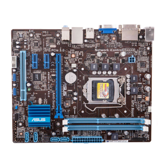
Motherboard Overview

    Place six screws into the holes indicated by circles to secure the motherboard to the chassis. Do not overtighten the screws! Doing so can damage the motherboard. Place this side towards the rear of the chassis P8H61-M LX2 R2.0 ASUS P8H61-M LX2 R2.0...
  • Page 13: Motherboard Layout

    1.2.3 Motherboard layout 19.8cm(7.8in) CPU_FAN KB_USB56 ATX12V USB34 LAN_USB12 Lithium Cell CHA_FAN CMOS Power AUDIO SATA3G_1 PCIEX16_1 SATA3G_2 8111F P8H61-M LX2 R2.0 PCIEX1_1 BIOS Intel ® asmedia Super ASM1083 PCIEX1_2 SATA3G_3 SB_PWR PCI1 SATA3G_4 VT1708S SPEAKER SPDIF_OUT USB78 USB910 F_PANEL...
  • Page 14: Central Processing Unit (Cpu)

    Contact your retailer immediately if the PnP cap is missing, or if you see any damage to the PnP cap/socket contacts/motherboard components. ASUS will shoulder the cost of repair only if the damage is shipment/transit-related. • Keep the cap after installing the motherboard. ASUS will process Return Merchandise Authorization (RMA) requests only if the motherboard comes with the cap on the LGA1155 socket.
  • Page 15 Lift the load lever in the direction of the arrow until the load plate is completely lifted. Load plate Remove the PnP cap from the CPU socket by lifting the tab only. PnP cap Position the CPU over the socket, ensuring that the gold triangle is on the bottom-left corner of the socket, and CPU notches...
  • Page 16 Close the load plate (A), and then push down the load lever (B), ensuring that the front edge of the load plate slides under the retention knob (C). Insert the load lever under the retention tab. ASUS P8H61-M LX2 R2.0...
  • Page 17: Installing The Cpu Heatsink And Fan

    1.3.2 Installing the CPU heatsink and fan The Intel LGA1155 processor requires a specially designed heatsink and fan assembly to ® ensure optimum thermal condition and performance. • When you buy a boxed Intel processor, the package includes the CPU fan and ®...
  • Page 18: Uninstalling The Cpu Heatsink And Fan

    Connect the CPU fan cable to the connector on the motherboard labeled CPU_FAN. CPU_FAN P8H61-M LX2 R2.0 P8H61-M LX2 R2.0 CPU fan connector Do not forget to connect the CPU fan connector! Hardware monitoring errors can occur if you fail to plug this connector.
  • Page 19: System Memory

    DDR2 DIMM socket. DDR3 modules are developed for better performance with less power consumption. The figure illustrates the location of the DDR3 DIMM sockets: Channel Sockets Channel A DIMM_A1 Channel B DIMM_B1 P8H61-M LX2 R2.0 P8H61-M LX2 R2.0 240-pin DDR3 DIMM sockets Chapter 1: Product introduction...
  • Page 20: Memory Configurations

    2.4 Ai Tweaker menu for manual memory frequency adjustment. • For system stability, use a more efficient memory cooling system to support a full memory load (2 DIMMs) or overclocking condition. P8H61-M LX2 R2.0 Motherboard Qualified Vendors Lists (QVL) DDR3-1066 MHz capability DIMM socket Chip...
  • Page 21 DDR3-1333 MHz capability DIMM socket Chip support Vendors Part No. Size Chip NO. Timing Voltage Brand 1DIMM 2DIMMs AD30908C8D-151C A-DATA AD31333001GOU A-Data E0906 A-DATA AD3U1333C2G9 A-DATA 3CCD-1509HNA1126L A-DATA AM2U139C2P1 ADATA 3CCD-1509A EL1127T A-DATA AX3U1333C2G9-BP A-DATA AD31333G001GOU 3GB(3 x 1GB) 8-8-8-24 1.65-1.85V 1.25V- A-DATA AXDU1333GC2G9-2G(XMP)
  • Page 22 2GB DIMM PC3-10666 SAMSUNG K4B1G0846D Kingtiger KTG2G1333PG3 MARKVISION BMD32048M1333C9-1123 MARKVISION M3D1288P-13 MARKVISION BMD34096M1333C9-1124 MARKVISION M3D2568E-13 PATRIOT PSD31G13332H PATRIOT PSD31G13332 PATRIOT PM64M8D38U-15 PATRIOT PSD32G13332H PATRIOT PG38G1333EL(XMP) 9-9-9-24 1.5V RAMAXEL RMR1870ED48E8F-1333 ELPIDA J1108BDBG-DJ-F RAMAXEL RMR1870EC58E9F-1333 ELPIDA J2108BCSE-DJ-F 1-12 ASUS P8H61-M LX2 R2.0...
  • Page 23 DDR3-1333 MHz capability DIMM socket support Vendor Part No. Size Chip Brand Chip NO. Timing Voltage 1DIMM 2DIMMs RiDATA C304627CB1AG22Fe RiDATA RiDATA E304459CB1AG32Cf RiDATA SILICON SP001GBLTU133S01 NANYA NT5CB128M8AN-CG POWER SILICON SP001GBLTU133S02 Elixir N2CB1680AN-C6 POWER Silicon Power SP002GBLTU133V02 S-POWER 20YT3NG-1202 SILICON SP002GBLTU133S02 Elixir N2CB1680AN-C6...
  • Page 24 6GB (3 x Mushkin 998659(XMP) 9-9-9-24 1.5~1.6V 2GB) 32GB PATRIOT PGD316G1600ELK(XMP) 9-9-9-24 1.65V (8GBx4) 4GB (2 x PATRIOT PGS34G1600LLKA 7-7-7-20 1.7V 2GB) SanMax SMD-4G68HP-16KZ HYNIX H5TQ2G83BFR PBC Silicon SP002GBLTU160V02(XMP) S-POWER 20YT5NG-1201 Power Silicon SP004GBLTU160V02(XMP) S-POWER 20YT5NG-1201 Power 1-14 ASUS P8H61-M LX2 R2.0...
  • Page 25 DDR3-1866 MHz capability DIMM socket Chip Chip support (optional) Vendors Part No. Size SS/DS Timing Voltage Brand 1DIMM 2DIMMs A-DATA AX3U1866PB2G8-DP2(XMP) 8-8-8-24 1.55V-1.75V 4GB(2 x CORSAIR CMT4GX3M2A1866C9(XMP) 9-9-9-24 1.65V 2GB) 6GB(3 x CORSAIR CMT6GX3MA1866C9(XMP) 9-9-9-24 1.65V 2GB) 8GB(2 x CORSAIR CMZ8GX3M2A1866C9(XMP) 9-10-9-27 1.50V...
  • Page 26 4GBPIS(XMP) GEIL GET34GB2400C9DC(XMP) 9-11-9-27 1.65V FLLE88F-C8KKAA KINGMAX 10-11-10-30 1.8V HAIS(XMP) TX2400KLU- Transcend 4GB(2 x 2GB) 1.65V 4GK(427652)(XMP) TX2400KLU-4GK Transcend 4GB(2x 2GB) 1.65V (381850)(XMP) TX2400KLU- Transcend 4GB(2x 2GB) 1.65V 4GK(374243)(XMP) PATRIOT PVV34G2400C9K(XMP) 4GB(2x 2GB) 9-11-9-27 1.65V 1-16 ASUS P8H61-M LX2 R2.0...
  • Page 27: Installing A Dimm

    1.4.3 Installing a DIMM Unplug the power supply before adding or removing DIMMs or other system components. Failure to do so can cause severe damage to both the motherboard and the components. Press the retaining clips outward to DIMM notch unlock a DIMM socket.
  • Page 28: Expansion Slots

    This motherboard supports PCI Express x1 network cards, SCSI cards, and other cards that comply with the PCI Express specifications. 1.5.5 PCI Express x16 slot This motherboard has a PCI Express 2.0 x16 slot that supports PCI Express x16 2.0 graphic cards complying with the PCI Express specifications. 1-18 ASUS P8H61-M LX2 R2.0...
  • Page 29: Jumpers

    Normal Clear RTC (Default) P8H61-M LX2 R2.0 Clear RTC RAM To erase the RTC RAM: 1. Turn OFF the computer and unplug the power cord. 2. Move the jumper cap from pins 1-2 (default) to pins 2-3. Keep the cap on pins 2-3 for about 5-10 seconds, then move the cap back to pins 1-2.
  • Page 30: Connectors

    Mic In Bass/Center Bass/Center Lime (Front panel) – – – Side Speaker Out To configure an 8-channel audio output: Use a chassis with HD audio module in the front panel to support 8-channel audio output. 1-20 ASUS P8H61-M LX2 R2.0...
  • Page 31: Internal Connectors

    Legacy AC’97 pin definition compliant definition P8H61-M LX2 R2.0 Front panel audio connector • We recommend that you connect a high-definition front panel audio module to this connector to avail of the motherboard’s high-definition audio capability. • If you want to connect a high-definition front panel audio module to this connector, set the Front Panel Type item in the BIOS setup to [HD].
  • Page 32 • If you are uncertain about the minimum power supply requirement for your system, refer to the Recommended Power Supply Wattage Calculator at http://support.asus. com/PowerSupplyCalculator/PSCalculator.aspx?SLanguage=en-us for details. Serial port connector (10-1 pin COM1) This connector is for a serial (COM) port.
  • Page 33 P8H61-M LX2 R2.0 +12V Rotation P8H61-M LX2 R2.0 CPU connectors Do not forget to connect the fan cables to the fan connectors. Insufficient air flow inside the system may damage the motherboard components. These are not jumpers! Do not place jumper caps on the fan connectors! The CPU_FAN connector supports a CPU fan of maximum 2A (24 W) fan power.
  • Page 34 S/PDIF Out module cable to this connector, then install the module to a slot opening at the back of the system chassis. P8H61-M LX2 R2.0 SPDIF_OUT P8H61-M LX2 R2.0 Digital audio connector The S/PDIF module is purchased separately. 1-24 ASUS P8H61-M LX2 R2.0...
  • Page 35: Speaker Connector 4-Pin Speaker

    PIN 1 P8H61-M LX2 R2.0 HD_LED RESET P8H61-M LX2 R2.0 System panel connector • System power LED (2-pin PLED) This 2-pin connector is for the system power LED. Connect the chassis power LED cable to this connector. The system power LED lights up when you turn on the system power, and blinks when the system is in sleep mode.
  • Page 36 PIN 1 PCICLK FRAME PCIRST# PWROWN LAD3 LAD2 LAD1 LAD0 SMBSCL SMBSDA +3VSB SERIRQ GPIO P8H61-M LX2 R2.0 SB_SUS_STAT RESET P8H61-M LX2 R2.0 TPM Connector The TPM module is purchased separately! 1-26 ASUS P8H61-M LX2 R2.0...
  • Page 37: Software Support

    The contents of the Support DVD are subject to change at any time without notice. Visit the ASUS website at www.asus.com for updates. To run the Support DVD Place the Support DVD into the optical drive.
  • Page 38 1-28 ASUS P8H61-M LX2 R2.0...
  • Page 39: Chapter 2 Bios Information

    BIOS in the future. Copy the original motherboard BIOS using the ASUS Update utility. 2.1.1 ASUS Update utility The ASUS Update is a utility that allows you to manage, save, and update the motherboard BIOS in Windows environment. ®...
  • Page 40: Asus Ez Flash 2

    Follow the onscreen instructions to complete the updating process. 2.1.2 ASUS EZ Flash 2 The ASUS EZ Flash 2 feature allows you to update the BIOS without using an OS-based utility. Before you start using this utility, download the latest BIOS file from the ASUS website at www.asus.com.
  • Page 41: Asus Crashfree Bios 3 Utility

    2.1.3 ASUS CrashFree BIOS 3 utility The ASUS CrashFree BIOS 3 is an auto recovery tool that allows you to restore the BIOS file when it fails or gets corrupted during the updating process. You can restore a corrupted BIOS file using the motherboard support DVD or a USB flash drive that contains the updated BIOS file.
  • Page 42: Asus Bios Updater

    2.1.4 ASUS BIOS Updater The ASUS BIOS Updater allows you to update the BIOS in a DOS environment. This utility also allows you to copy the current BIOS file for use as a backup when the BIOS fails or gets corrupted during the updating process.
  • Page 43 Backing up the current BIOS To backup the current BIOS file using the BIOS Updater Ensure that the USB flash drive is not write-protected and has at least 4MB free space to save the file. At the FreeDOS prompt, type bupdater /o[filename] and press <Enter>. D:\>bupdater /oOLDBIOS1.rom Filename Extension The [filename] is any user-assigned name with no more than eight alphanumeric...
  • Page 44: Updating The Bios File

    • Load the BIOS default settings to ensure system compatibility and stability. Select the Load Optimized Defaults item under the Exit menu. Refer to section 2.9 Exit menu for details. • Reconnect all SATA hard disk drives after updating the BIOS file if you have disconnected them. ASUS P8H61-M LX2 R2.0...
  • Page 45: Bios Setup Program

    • The BIOS setup screens shown in this section are for reference purposes only, and may not exactly match what you see on your screen. • Visit the ASUS website at www.asus.com to download the latest BIOS file for this motherboard.
  • Page 46: Bios Menu Screen

    Selects the boot selected mode on the right hand side device priority • The boot device options vary depending on the devices installed. • The Boot Menu(F8) button is available only when there is an available boot device. ASUS P8H61-M LX2 R2.0...
  • Page 47: Advanced Mode

    The Advanced Mode provides advanced options for experienced end-users to configure the BIOS settings. The figure below shows an example of the Advanced Mode. Refer to the following sections for the detailed configurations. To access the EZ Mode, click Exit, then select ASUS EZ Mode. Back button Menu items...
  • Page 48: Menu Items

    You cannot select an item that is not user- configurable. A configurable field is highlighted when selected. To change the value of a field, select it and press <Enter> to display a list of options. 2-10 ASUS P8H61-M LX2 R2.0...
  • Page 49: Main Menu

    Main menu The Main menu screen appears when you enter the Advanced Mode of the BIOS Setup program. The Main menu provides you with an overview of basic system information, and allows you to set the system date, time, language, and security settings. 2.3.1 System Language [English] Allows you to choose the BIOS language version from the options.
  • Page 50: Security

    To clear the administrator password, follow the same steps as in changing an administrator password, but press <Enter> when prompted to create/confirm the password. After you clear the password, the Administrator Password item on top of the screen shows Not Installed. 2-12 ASUS P8H61-M LX2 R2.0...
  • Page 51: User Password

    User Password If you have set a user password, you must enter the user password for accessing the system. The User Password item on top of the screen shows the default Not Installed. After you set a password, this item shows Installed. To set a user password: Select the User Password item and press <Enter>.
  • Page 52: Ai Tweaker Menu

    [DDR3-1066MHz] [DDR3-1333MHz] [DDR3-1600MHz] [DDR3-1866MHz] [DDR3-2133MHz] [DDR3-2400MHz] Selecting a very high memory frequency may cause the system to become unstable! If this happens, revert to the default setting. Memory frequency options would depend on installed CPU. 2-14 ASUS P8H61-M LX2 R2.0...
  • Page 53: Oc Tuner

    2.4.3 OC Tuner OC Tuner automatically overclocks the frequency and voltage of CPU and DRAM for enhancing the system performance. Press <Enter> and select OK to start automatic overclocking. Configuration options: [OK] [Cancel] 2.4.4 DRAM Timing Control The sub-items in this menu allow you to set the DRAM timing control features. Use the <+> and <->...
  • Page 54: Advanced Menu

    The Advanced menu items allow you to change the settings for the CPU and other system devices. Be cautious when changing the settings of the Advanced menu items. Incorrect field values can cause the system to malfunction. 2-16 ASUS P8H61-M LX2 R2.0...
  • Page 55: Cpu Configuration

    2.5.1 CPU Configuration The items in this menu show the CPU-related information that the BIOS automatically detects. The items shown in submenu may be different due to the CPU you installed. Scroll down to display the following items: Intel Adaptive Thermal Monitor [Enabled] [Enabled] Enables the overheated CPU to throttle its clock speed to cool down.
  • Page 56: Cpu Power Management Configuration

    Allows processor cores to run faster than marked frequency in specific condition. [Disabled] Disables this function. CPU C1E [Auto] [Enabled] Enables the C1E support function. This item should be enabled in order to enable the Enhanced Halt State. [Disabled] Disables this function. 2-18 ASUS P8H61-M LX2 R2.0...
  • Page 57: Pch Configuration

    CPU C3 Report [Auto] Allows you to disable or enable the CPU C3 report to OS. CPU C6 Report [Auto] Allows you to disable or enable the CPU C6 report to OS. 2.5.2 PCH Configuration High Precision Timer [Enabled] Allows you to enable or disable the High Precision Event Timer. Configuration options: [Enabled] [Disabled] Intel(R) Rapid Start Technology Intel(R) Rapid Start Technology [Disabled]...
  • Page 58: Sata Configuration

    S.M.A.R.T. (Self-Monitoring, Analysis and Reporting Technology) is a monitor system. When read/write of your hard disk errors occur, this feature allows the hard disk to report warning messages during the POST. Configuration options: [Enabled] [Disabled] 2-20 ASUS P8H61-M LX2 R2.0...
  • Page 59: System Agent Configuration

    • Due to H61 Chipset limitation, AHCI Mode only works on Windows Vista / Windows ® ® Please use IDE Mode on Windows ® • [IDE] is the default SATA type. Under Windows XP, there is no need to change the ®...
  • Page 60: Onboard Devices Configuration

    Allows you to enable or disable the serial port (COM). Configuration options: [Enabled] [Disabled] Change Settings [IO=3F8h; IRQ=4] Allows you to select the Serial Port base address. Configuration options: [IO=3F8h; IRQ=4] [IO=2F8h; IRQ=3] [IO=3E8h; IRQ=4] [IO=2E8h; IRQ=3] 2-22 ASUS P8H61-M LX2 R2.0...
  • Page 61: Apm

    2.5.7 Restore AC Power Loss [Power Off] [Power On] The system goes into on state after an AC power loss. [Power Off] The system goes into off state after an AC power loss. [Last State] The system goes into either off or on state, whatever the system state was before the AC power loss.
  • Page 62: Monitor Menu

    The onboard hardware monitor automatically detects and displays the CPU and chassis fan speeds in rotations per minute (RPM). If the fan is not connected to the motherboard, the field shows N/A. Select Ignore if you do not wish to display the detected speed. 2-24 ASUS P8H61-M LX2 R2.0...
  • Page 63: Cpu Voltage, 3.3V Voltage, 5V Voltage, 12V Voltage

    2.6.3 CPU Voltage, 3.3V Voltage, 5V Voltage, 12V Voltage The onboard hardware monitor automatically detects the voltage output through the onboard voltage regulators. Select Ignore if you do not want to detect this item. 2.6.4 CPU Q-Fan Control [Enabled] [Disabled] Disables the CPU Q-Fan control feature.
  • Page 64: Anti Surge Support [Enabled]

    60% to 100%. When the chassis temperature is under 40ºC, the chassis fan will operate at the minimum duty cycle. 2.6.6 Anti Surge Support [Enabled] This item allows you to enable or disable the Anti Surge function. Configuration options: [Disabled] [Enabled] 2-26 ASUS P8H61-M LX2 R2.0...
  • Page 65: Boot Menu

    [Disabled] Disables the full screen logo display feature. Set this item to [Enabled] to use the ASUS MyLogo 2™ feature. Post Report [5 sec] This item appears only when the Full Screen Logo item is set to [Disabled] and allows you to set the waiting time for the system to display the post report.
  • Page 66: Option Rom Messages [Force Bios]

    • To select the boot device during system startup, press <F8> when ASUS Logo appears. • To access Windows OS in Safe Mode, press <F8> after POST.
  • Page 67: Tools Menu

    <Enter> to display the submenu. 2.8.1 ASUS EZ Flash Utility Allows you to run ASUS EZ Flash 2. Press [Enter] to launch the ASUS EZ Flash 2 screen. For more details, see section 2.1.2 ASUS EZ Flash 2. 2.8.2...
  • Page 68: Exit Menu

    This option allows you to enter the EZ Mode screen. Launch EFI Shell from filesystem device This option allows you to attempt to launch the EFI Shell application (shellx64.efi) from one of the available devices that have a filesystem. 2-30 ASUS P8H61-M LX2 R2.0...
  • Page 69: Appendices

    Appendices Notices Federal Communications Commission Statement This device complies with Part 15 of the FCC Rules. Operation is subject to the following two conditions: • This device may not cause harmful interference. • This device must accept any interference received including interference that may cause undesired operation.
  • Page 70: Canadian Department Of Communications Statement

    ASUS Recycling/Takeback Services ASUS recycling and takeback programs come from our commitment to the highest standards for protecting our environment. We believe in providing solutions for you to be able to responsibly recycle our products, batteries, other components as well as the packaging materials. Please go to http://csr.asus.com/english/Takeback.htm for the detailed recycling information in different...
  • Page 71: Asus Contact Information

    +1-510-739-3777 +1-510-608-4555 Web site usa.asus.com Technical Support Telephone +1-812-282-2787 Support fax +1-812-284-0883 Online support support.asus.com ASUS COMPUTER GmbH (Germany and Austria) Address Harkort Str. 21-23, D-40880 Ratingen, Germany +49-2102-959911 Web site www.asus.de Online contact www.asus.de/sales Technical Support Telephone +49-1805-010923* Support Fax...
  • Page 72 ASUS P8H61-M LX2 R2.0...

Table of Contents