
Related Manuals for Phoenix Contact UM EN AXL F PSDI8/4 1F


Summary of Contents for Phoenix Contact UM EN AXL F PSDI8/4 1F
- Page 1 Axioline F safety module with safe digital inputs User manual UM EN AXL F PSDI8/4 1F...
- Page 2 User manual Axioline F safety module with safe digital inputs 2016-11-22 Designation: UM EN AXL F PSDI8/4 1F Revision: Order No.: This user manual is valid for: Designation From HW/FW Order No. revision AXL F PSDI8/4 1F 01/220 2701559 PHOENIX CONTACT...
- Page 3 How to contact us Internet Up-to-date information on Phoenix Contact products and our Terms and Conditions can be found on the Internet at: phoenixcontact.com Make sure you always use the latest documentation.
- Page 4 The receipt of technical documentation (in particular user documentation) does not constitute any further duty on the part of Phoenix Contact to furnish information on modifications to products and/or technical documentation. You are responsible to verify the suitability and intended use of the products in your specific application, in particular with regard to observing the applicable standards and regulations.
-
Page 5: Table Of Contents
Programming data/configuration data..............22 Integration of the Axioline F local bus ..................23 Supply voltage of the module logic ..............23 Supply voltage U ....................23 DC distribution network according to IEC 61326-3-1 ........... 24 Terminal point assignment................... 25 105738_en_04 PHOENIX CONTACT... - Page 6 Two-channel non-equivalent assignment of safe inputs ........57 7.5.1 Notes on errors ..................59 7.5.2 Cross-circuit monitoring enabled, supply through T1 and T2 ....60 7.5.3 Cross-circuit monitoring disabled, supply through a clock output or external supply ..............61 PHOENIX CONTACT 105738_en_04...
- Page 7 AXL F PSDI8/4 1F module data................83 11.3 Conformance with EMC Directive................ 87 11.4 Ordering data and download data ............... 87 11.4.1 Ordering data: module ................. 87 11.4.2 Download data: documentation ............87 11.4.3 Download data: software ..............88 105738_en_04 PHOENIX CONTACT...
- Page 8 ....................... 92 Diagnostic messages for parameter errors for PROFIsafe ......... 93 Appendix: index ........................95 Appendix: checklists .........................97 Planning ......................98 Assembly and electrical installation ............... 99 Startup and parameterization ............... 100 Validation ......................101 Appendix: revision history.......................103 PHOENIX CONTACT 105738_en_04...
-
Page 9: For Your Safety
The safety of personnel and equipment can only be assured if the module is used correctly: equipment see Section 1.5 “Intended use” on page 11. Error detection Depending on the wiring and the parameterization, the module detects errors within the safety equipment. 105738_en_04 PHOENIX CONTACT... -
Page 10: Electrical Safety
In this case, the correct operation of the safety module can no longer be ensured. In the event of an error, send the module to Phoenix Contact or contact Phoenix Contact immediately and engage a service engineer. -
Page 11: Safety Of The Machine Or System
Single or two-channel emergency stop equipment or safety door equipment – Applications with enable button – Applications with two-hand control devices – Applications with mode selector switches – As secondary switchgear for safety-related photoelectric barriers – Safety circuits according to EN 60204, Part 1 105738_en_04 PHOENIX CONTACT... -
Page 12: Documentation
Explanations of terms and abbreviations used in the context of PROFIsafe: see “Appendix: glossary for PROFIsafe” on page 89. Safety hotline Should you have any technical questions, please contact our 24-hour hotline. Phone: + 49 5281 9-46277, e-mail: safety-service@phoenixcontact.com PHOENIX CONTACT 105738_en_04... -
Page 13: Product Description
In the PROFIsafe system, the module can be used to achieve safety functions with the following requirements depending on the operating conditions: – Up to SIL 3 according to IEC 61508 – Up to SILCL 3 according to EN 62061 – Up to Cat. 4/PL e according to EN ISO 13849-1 105738_en_04 PHOENIX CONTACT... -
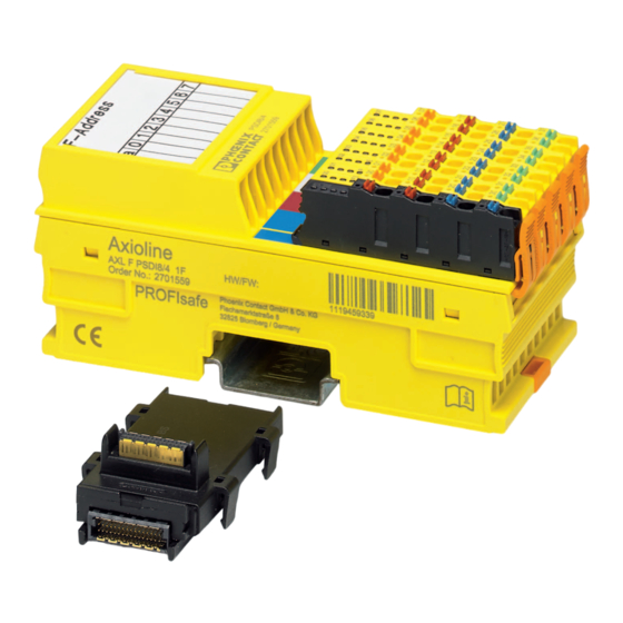
Page 14: Structure Of The Module
Connector for connecting the supply voltage Function identification I/O connector Diagnostics and status indicators DIP switch More detailed information on setting the switch: see Section 4.1.3 “Setting the DIP switch” on page 28. Housing dimensions 53.6 Figure 2-2 Housing dimensions (in mm) PHOENIX CONTACT 105738_en_04... -
Page 15: Safe Digital Inputs And Clock Outputs T1 And T2
Use suitable sensors/controlling devices which are described in the applicable safety devices standards, for example. The module's ability to detect errors depends on the parameterization. • Adapt the module parameterization to the relevant sensor/controlling device: see Section 5 “Parameterization of the module” on page 33. 105738_en_04 PHOENIX CONTACT... -
Page 16: Clock Outputs T1 And T2
LED. This error must be acknowledged so that the system can be started up again following error removal, see Section 9 “Errors: messages and removal” on page 69. As there are two clock outputs for eight inputs, there may be reciprocal effects between the inputs. PHOENIX CONTACT 105738_en_04... - Page 17 Inputs for channel 1 (INx_CH1) are assigned to clock output T1. – Inputs for channel 2 (INx_CH2) are assigned to clock output T2. Observe the information on error detection according to clocking: see Section 2.4.2 “Clock outputs T1 and T2” on page 16. 105738_en_04 PHOENIX CONTACT...
-
Page 18: Connection Options For Sensors Depending On The Parameterization
– Contact-based – With OSSD outputs Achievable safety integrity SILCL Cat. For connection example, see page Cat. 3 can only be achieved with a redundant sensor. The category that can be achieved depends on the sensor used. PHOENIX CONTACT 105738_en_04... -
Page 19: Local Diagnostics And Status Indicators
(Only applies if UI is on or flashing at the same time.) Red on Hardware fault. Communication to the higher-level controller is disabled. The module has entered the safe state (failure state). Flashing red The module is not parameterized. 105738_en_04 PHOENIX CONTACT... - Page 20 A diagnostic message is present that needs to be acknowledged for safe digital input errors, supply voltage errors or general errors. 00 - 07 Green Status of each input from 0 - 7 Input at logic “0”. Green on Input at logic “1”. PHOENIX CONTACT 105738_en_04...
-
Page 21: Safe State
Overload/short circuit of the clock outputs The diagnostic message is transmitted to the controller: see Section 9 “Errors: messages and removal” on page 69. Information on which errors occur and when: see Section 7 “Connection examples for safe inputs” on page 39. 105738_en_04 PHOENIX CONTACT... -
Page 22: Device Errors
Section 9.2.4 “Parameterization errors” on page 78. Programming data/configuration data Phoenix Contact provides device description files for various control systems. The programming data/configuration data is defined in the device description (FDCML, GSD, GSDML, etc.) according to the bus or network used. -
Page 23: Integration Of The Axioline F Local Bus
Observe the general safety notes: see Section 1.2 “Electrical safety” on page 10. Supply voltage U supplies the input circuits, the clock outputs, and the switching elements on the I/O side. Technical data for supply voltage U : see “Supply voltage U (sensors, clock outputs, I/O)” on page 85. 105738_en_04 PHOENIX CONTACT... -
Page 24: Dc Distribution Network According To Iec 61326-3-1
DC voltage and to which any device is connected. A typical system or machine distribution is not a DC distribution network. For devices that are intended for a typical system or machine distribution, the DC connections are viewed and tested as I/O signals according to IEC 61326-3-1. PHOENIX CONTACT 105738_en_04... -
Page 25: Terminal Point Assignment
Table 3-1 Terminal point assignment of the voltage connection Terminal point Color Assignment a1, a2 24 V DC (UI) UI: supply of the digital inputs (internally connected) b1, b2 Blue Reference potential of the supply voltage (internally connected) 105738_en_04 PHOENIX CONTACT... - Page 26 Blue Function Terminal point Green Function WARNING: Loss of safety function Parasitic voltages can result in the loss of the safety function. • Wire sensors that require a GND to the corresponding slot for 0 V (GND). PHOENIX CONTACT 105738_en_04...
-
Page 27: Assembly, Removal, And Electrical Installation
Mount the module on a 35 mm DIN rail in a control cabinet or junction box protected from dust and humidity (IP54 or higher). • Secure the control cabinet/junction box to prevent unauthorized opening. • Only connect the cables using the supplied Axioline F connectors. 105738_en_04 PHOENIX CONTACT... -
Page 28: Setting The Dip Switch
Remove the marking field and set the address in the switch below it. • Reattach the marking field to the module. The set address is only applied on power up. If the address is adjusted during operation, the module responds with a failure state. PHOENIX CONTACT 105738_en_04... -
Page 29: Mounting And Removing Modules
Insert a suitable tool (e.g., bladed screwdriver) into the upper and lower snap- on mechanisms (base latches) of the module one after the other to release it (A). • Remove the module perpendicular to the DIN rail (B). 105738_en_04 PHOENIX CONTACT... - Page 30 • Press firmly on the connector. Make sure that the locking latch snaps in. Remove • Release the locking latch (A). • Tilt the connector upwards slightly (B). • Remove the connector from the module (C). PHOENIX CONTACT 105738_en_04...
-
Page 31: Electrical Installation
I/O devices is fed directly to the module. The sensors are connected via Axioline F connectors. • Wire the connectors according to your application: see Section 3.4 “Terminal point assignment” on page 25. 105738_en_04 PHOENIX CONTACT... - Page 32 AXL F PSDI8/4 1F PHOENIX CONTACT 105738_en_04...
-
Page 33: Parameterization Of The Module
Information on error messages and troubleshooting: see Section 9 “Errors: messages and removal” on page 69. F-Parameters and Assign the parameterizable F-Parameters and i-Parameters. Overview of the module i-Parameters parameters and possible settings: see Section B “Appendix: F-Parameters and i- Parameters” on page 91. 105738_en_04 PHOENIX CONTACT... -
Page 34: Parameterization Of The Safe Inputs
The filter time affects the response time of the safety function. Symmetry Disabled Parameterization is only active if the input is parameterized 100 ms for two-channel operation. See also “Symmetry/ start inhibit” on page 35. PHOENIX CONTACT 105738_en_04... - Page 35 For non-equivalent parameterization, a negated signal is present at input IN0_Ch2 as illustrated. IN0_Ch1 IN0_Ch1 IN0_Ch2 IN0_Ch2 Diag Diag 76020007 Figure 5-1 Example for a signal change in the parameterized time for symmetry monitoring 105738_en_04 PHOENIX CONTACT...
- Page 36 Filter demand Filter Where: Processing time of the input Parameterized filter time Filter Firmware runtime: 1 ms PHOENIX CONTACT 105738_en_04...
-
Page 37: Duration Of A Safety Demand
Observe the behavior of the controller when processing the safe inputs. • In addition to the processing time of input t , observe the system-specific PROFIsafe behavior (e.g., watchdog time, duration of demand, processing time of the safe controller). 105738_en_04 PHOENIX CONTACT... - Page 38 AXL F PSDI8/4 1F PHOENIX CONTACT 105738_en_04...
-
Page 39: Connection Examples For Safe Inputs
The examples only describe the options for the electrical connection of sensors to the safe inputs. Should you have any questions regarding your applications, please contact the Phoenix Contact safety hotline: see Section 1.8 “Safety hotline” on page 12. The following are specified for each example: –... -
Page 40: Measures To Achieve A Specific Safety Integrity
PFD and PFH depending on the SIL/SILCL Safety integrity SIL 2/SILCL 2 1% of 10 1% of 10 SIL 3/SILCL 3 1% of 10 1% of 10 Performance level Use standard EN ISO 13849-1 to determine the performance level. PHOENIX CONTACT 105738_en_04... - Page 41 If single-channel sensors are not available for this category, use two-channel sensors. An accumulation of errors must not result in the loss of the safety function. Following the third error, evaluation can be aborted if the probability of further errors occurring is low. 105738_en_04 PHOENIX CONTACT...
-
Page 42: Single-Channel Assignment Of Safe Inputs
If an input pair is parameterized as single-channel with cross-circuit monitoring, the fixed assignment is as follows: – INx_Ch1 is permanently assigned to clock output T1 – INx_Ch2 is permanently assigned to clock output T2 Safety switch IN1_Ch1 Figure 7-1 Single-channel assignment of inputs PHOENIX CONTACT 105738_en_04... - Page 43 “1” of the input. An unexpected change from “0” to “1” is possible. Make sure that this change in state cannot restart the system unintentionally. Clock output to ground Short circuit No The affected clock output is disabled. SF = safety function 105738_en_04 PHOENIX CONTACT...
-
Page 44: Cross-Circuit Monitoring Disabled, Supply Through T1
Internally through clock output T1 or T2; cross-circuit monitoring disabled – External (24 V) Achievable SIL/SILCL/Cat./PL SIL 2/SILCL 2/Cat. 2/PL d WARNING: Loss of safety function Cross-circuits can result in the loss of the safety function. • Prevent cross-circuits to achieve the specified PL. PHOENIX CONTACT 105738_en_04... - Page 45 The error is only detected as a change in state from “1” to “0” in state “1” of the input. An unexpected change from “0” to “1” is possible. Make sure that this change in state cannot restart the system unintentionally. SF = safety function 105738_en_04 PHOENIX CONTACT...
-
Page 46: Supply Through Ossd
Single-channel OSSD output (with internal testing) Sensor supply External (OSSD sensor) Achievable SIL/SILCL/Cat./PL SIL 2/SILCL 2/Cat. 2/PL d WARNING: Loss of safety function Cross-circuits can result in the loss of the safety function. • Prevent cross-circuits to achieve the specified PL. PHOENIX CONTACT 105738_en_04... - Page 47 The error is only detected as a change in state from “1” to “0” in state “1” of the input. An unexpected change from “0” to “1” is possible. Make sure that this change in state cannot restart the system unintentionally. SF = safety function 105738_en_04 PHOENIX CONTACT...
-
Page 48: Two-Channel Equivalent Assignment Of Safe Inputs
Please note that if a delayed change in state at one of the two inputs causes the safety switch to be switched on again, this can result in delayed transmission of state “1” in the process data image of the inputs. PHOENIX CONTACT 105738_en_04... - Page 49 “0” if a “0” signal is present at at least one of the two inputs or an error has been detected – “1” if a “1” signal is present at both inputs and no error has been detected and the conditions are met for a change in state according to Figure 7-6 105738_en_04 PHOENIX CONTACT...
-
Page 50: Notes On Errors
The message must be acknowledged. Following acknowledgment, the current status of the inputs is displayed in the process data image of the inputs. – The message can be used to monitor the wear of the safety switch. PHOENIX CONTACT 105738_en_04... -
Page 51: Cross-Circuit Monitoring Enabled, Supply Through T1 And T2
The error is detected in state “1” or on a change in state from “0” to (cable interrupt between clock violation “1”, as the state only changes in one channel. output and sensor or between sensor and input) Cross-circuit Input to input Cross-circuit No The error is detected in state “1” 105738_en_04 PHOENIX CONTACT... - Page 52 Typical parameterization Parameterization Parameterized as/value range Comment Input xx channel 1/channel 2 Assignment Two-channel equivalent Filter time (t 3 ms Application-specific Filter Symmetry 100 ms Application-specific Start inhibit due to symmetry Enabled Application-specific violation Cross-circuit monitoring Cross-circuit monitoring PHOENIX CONTACT 105738_en_04...
-
Page 53: Output Or External Supply
On a change in state from “0” to “1”, a “0” is transmitted in the violation process data image of the affected inputs, as only one channel reports this change in state. Other errors Please take into consideration all errors that can occur in the sensor. (depending on the sensor) 105738_en_04 PHOENIX CONTACT... - Page 54 For all inputs that are parameterized without cross-circuit monitoring, cross-circuits and short circuits are not detected by the device diagnostics, but only on a change in state of the input signals, as the state only changes in one channel. PHOENIX CONTACT 105738_en_04...
-
Page 55: External Supply (Ossd)
Connect the sensor ground directly to terminal point GND of the safety module. An external ground may not be used. Basic specifications Sensor Two-channel OSSD output (with internal testing) Sensor supply External (OSSD sensor) Achievable SIL/SILCL/Cat./PL SIL 3/SILCL 3/Cat. 4/PL e 105738_en_04 PHOENIX CONTACT... - Page 56 The error is detected in state “1” or on a change in state from “0” to violation “1”, as the state only changes in one channel. SF = safety function Only applies when symmetry monitoring is active PHOENIX CONTACT 105738_en_04...
-
Page 57: Two-Channel Non-Equivalent Assignment Of Safe Inputs
Please note that if a delayed change in state at one of the two inputs causes the safety switch to be switched on again, this can result in delayed transmission of state “1” in the process data image of the inputs. 105738_en_04 PHOENIX CONTACT... - Page 58 “1” if a “1” signal is present at channel 1 of the input and a “0” signal is present at channel 2 of the input and no error has been detected and the conditions are met for a change in state according to Figure 7-12. – “0” is transmitted in all other cases. PHOENIX CONTACT 105738_en_04...
-
Page 59: Notes On Errors
The message must be acknowledged. Following acknowledgment, the current status of the inputs is displayed in the process data image of the inputs. – The message can be used to monitor the wear of the safety switch. 105738_en_04 PHOENIX CONTACT... -
Page 60: Cross-Circuit Monitoring Enabled, Supply Through T1 And T2
The error is detected for inputs which are assigned to different clock outputs. Short circuit Input to ground None The error is detected on a change in state at the latest, as the state only changes in one channel. PHOENIX CONTACT 105738_en_04... -
Page 61: Output Or External Supply
Cross-circuit monitoring disabled, supply through a clock output or external supply S1, S2 IN1_Ch1 Two switching elements IN1_Ch2 T1 (T2) Supply through T1 or T2 T1 (T2) Figure 7-14 Two-channel non-equivalent assignment of inputs, supply through T1 (or T2), cross-circuit monitoring disabled 105738_en_04 PHOENIX CONTACT... - Page 62 Change in state from “1” to “0”: The faulty input remains at “1”. A “0” is transmitted in the process data image of the affected inputs. Clock output to clock output None The error is not detected. PHOENIX CONTACT 105738_en_04...
- Page 63 Parameterization Parameterized as/value range Comment Input xx channel 1/channel 2 Assignment Two-channel non-equivalent Filter time (t 3 ms Application-specific Filter Symmetry 100 ms Application-specific Start inhibit due to symmetry Enabled Application-specific violation Cross-circuit monitoring No cross-circuit monitoring 105738_en_04 PHOENIX CONTACT...
- Page 64 AXL F PSDI8/4 1F PHOENIX CONTACT 105738_en_04...
-
Page 65: Startup And Validation
Instructions on how to proceed in the event of an error: see and status indicators to check whether the module has Section 9 “Errors: messages and removal” on page 69 started up correctly or whether any errors are indicated. 105738_en_04 PHOENIX CONTACT... -
Page 66: Startup Mode
The red CM LED indicates that the device is in startup mode. In the Startup+ software, enter the address set on the device. For additional information on the Startup+ software, refer to the documentation for the software. The software can be downloaded free of charge at phoenixcontact.net/products. PHOENIX CONTACT 105738_en_04... -
Page 67: Restart After Replacing A Module
The variables used in your application program have been linked to the safe sensors correctly. • Perform a function test and error simulation. Observe the information on validation provided in the checklist: see Section D 4 “Validation” on page 101. 105738_en_04 PHOENIX CONTACT... - Page 68 AXL F PSDI8/4 1F PHOENIX CONTACT 105738_en_04...
-
Page 69: Errors: Messages And Removal
IN3_CH2 “Channel” diagnostics Example: In the event of a short circuit at terminal point 05 of input IN2_CH2, value 0x05 is indicated in DiagState object 0x0018, subindex 3. The error is located in the “Channel 5” diagnostics. 105738_en_04 PHOENIX CONTACT... - Page 70 Value without sign bit, only positive values from 00 ... FF Unsigned 16 Value without sign bit, only positive values from 0000 ... FFFF Unsigned 32 Value without sign bit, only positive values from 0000 0000 ... FFFF FFFF PHOENIX CONTACT 105738_en_04...
-
Page 71: Diagstate Object 0X0018
DiagStateChannelNo object Index Object Object Data Rights Meaning name type type [bytes] 0x0033 DiagState- Record Diagnostic state ChannelNo Consecutive Unsigned 16 Consecutive error number since the last reset or error memory reset ChannelNo Unsigned 8 Affected channel 105738_en_04 PHOENIX CONTACT... -
Page 72: Diagstateaddvalue Object 0X0034
The next error is then output. Table 9-8 ResetDiag object Index Object Object Data Rights Meaning name type type [bytes] 0x0019 ResetDiag Unsigned 8 Reset diagnostics; deletes the corresponding diagnostic memory and acknowledges the message PHOENIX CONTACT 105738_en_04... -
Page 73: Examples For Reading A Diagnostic Message
Text: Read DiagStateChannelNo object 0x0033 Consecutive no.: 2 ChannelNo: 0x0000 Read DiagStateAddValue object 0x0034 Consecutive no.: 2 AddValue: 0x0340 This error cannot be acknowledged as it is a priority 1 error. • Check and correct the parameterization. 105738_en_04 PHOENIX CONTACT... -
Page 74: Error Codes
AXL F PSDI8/4 1F Error codes Please contact Phoenix Contact if error codes are indicated by the system which do not appear in: – The tables below in this user manual – The Axioline F: system and installation user manual, UM EN AXL F SYS INST –... -
Page 75: Safe Digital Input Errors
As a result all inputs are kept in the This diagnostic message can be safe state. acknowledged. Acknowledgment deletes the message. Restart is only possible following an error-free power up selftest. If the power up selftest is not error- free, the module must be replaced. 105738_en_04 PHOENIX CONTACT... - Page 76 Acknowledgment If the start inhibit due to symmetry deletes the message. violation is activated, the inputs are disabled until the diagnostic message is acknowledged. Otherwise the input information continues to be collected and sent to the controller. PHOENIX CONTACT 105738_en_04...
-
Page 77: Clock Output Errors
This diagnostic message can be All module inputs are kept in the safe acknowledged. Acknowledgment state. deletes the message and enables The U LED is permanently on again the inputs. as soon as no undervoltage can be detected. 105738_en_04 PHOENIX CONTACT... -
Page 78: Parameterization Errors
0x6320 Device type ID is Check whether the correct module is incorrect or wrong being used. + 0x03FB module is being used If you are unable to remove the error, please contact Phoenix Contact. PHOENIX CONTACT 105738_en_04... -
Page 79: General Errors
DIP switch moved during FS on The module switches to the safe Check DIP switch position. operation state. Perform power up. This diagnostic message cannot be acknowledged. 105738_en_04 PHOENIX CONTACT... -
Page 80: Profisafe Errors
– A safety-related input is automatically reset to “1” when the safety function trigger is reset. • If you do not want the machine to restart automatically, configure the safety logic accordingly. PHOENIX CONTACT 105738_en_04... -
Page 81: 10 Maintenance, Repair, Decommissioning, And Disposal
In this case, the correct operation of the safety module can no longer be ensured. • In the event of an error, send the module to Phoenix Contact or contact Phoenix Contact immediately and engage a service engineer. 10.3... - Page 82 AXL F PSDI8/4 1F PHOENIX CONTACT 105738_en_04...
-
Page 83: 11 Technical Data And Ordering Data
Gases that may endanger functions according to DIN 40046-36, Not resistant to gas that may endanger functions (sulfur dioxide (SO DIN 40046-37 hydrogen sulfide (H Resistance of the housing material to fungal decay Resistant Ambient compatibility Not resistant to organic chlorine compounds 105738_en_04 PHOENIX CONTACT... - Page 84 18, see Section 7 “Connection examples for safe inputs” on page 39 Diagnostic coverage (DC) Mean time to dangerous failure (MTTFd) 100 years (regardless of whether single-channel or two-channel assignment) PHOENIX CONTACT 105738_en_04...
- Page 85 1.5/3/5/15 ms (can be parameterized): see “Filter time (t )” on page 34 Filter Filter Accuracy of filter time +0 ms, -0.5 ms Processing time of the input Filter See “Processing time of input t in the event of a safety demand” on page 36 105738_en_04 PHOENIX CONTACT...
- Page 86 Saturation voltage - 1 V Simultaneity 100% Derating Permissible cable lengths The total length of the connected cables must not exceed 1000 m per clock output Status indicators None Approvals For the latest approvals, please visit phoenixcontact.net/products. PHOENIX CONTACT 105738_en_04...
-
Page 87: Conformance With Emc Directive
Axioline F: diagnostic registers and error messages PROFIsafe Specification profisafe.net PROFIsafe - Profile for Safety Technology on PROFIBUS DP and PROFINET IO, Version 2.4, February 2007 Documentation for PROFIsafe, PROFIBUS, and PROFINET is available on the Internet at profibus.com/download/. 105738_en_04 PHOENIX CONTACT... -
Page 88: Download Data: Software
Download data: software Make sure you always use the latest software. The software can be downloaded free of charge at phoenixcontact.net/products. Description Type Download area for Order STARTUP+ Software for starting up and parameterizing Axioline stations STARTUP+ 2700636 PHOENIX CONTACT 105738_en_04... -
Page 89: A Appendix: Glossary For Profisafe
F-Device. F_Par_CRC A CRC signature which is created via all F-Parameters and ensures error-free transmission of the F-Parameters. F-Slave Failsafe slave F-Source_Address F-Parameter, PROFIsafe source address; address of the safe controller (see also „F-Parameter“) 105738_en_04 PHOENIX CONTACT... - Page 90 DIP switches and then configure it in the configuration tool for the safe controller. PROFIsafe monitoring Monitoring time for safety-related communication between the safe controller (F-CPU) and time safe I/O device (F-I/O device). This time is parameterized in the F_WD_Time F-Parameter. PHOENIX CONTACT 105738_en_04...
-
Page 91: B Appendix: F-Parameters And I-Parameters
The value must be greater than 0. When verifying the safety function, check whether the F_iPar_CRC parameter is greater than 0 for all modules. If not, check the i-Parameters and the CRC checksum in the i-Parameter and F-Parameter. 105738_en_04 PHOENIX CONTACT... -
Page 92: B 2 I-Parameters
The i-Parameters are individual module parameters. These include: – Module parameters: see Section 5.2 “Parameterization of the safe inputs” on page 34 – PST_Device_ID (device type ID) iPar_CRC The module parameters are verified with a checksum: iPar_CRC. PHOENIX CONTACT 105738_en_04... -
Page 93: B 3 Diagnostic Messages For Parameter Errors For Profisafe
CRC1 transmitted in the parameter telegram. Device-specific diagnostics. Save i-Parameter watchdog time exceeded. Restore i-Parameter watchdog time exceeded. Invalid F_iParCRC. Correct value. F_Block_ID is not supported. Check device description. Reserved. Reserved. Non-specified (unknown) error 105738_en_04 PHOENIX CONTACT... - Page 94 AXL F PSDI8/4 1F Table B-3 i-Parameter parameter errors AddValue Error cause Remedy (hex) 03F2 iPar_CRC is incorrect. Check i-Parameters. Repeat calculation. 03FB PST_Device_ID is incorrect. Contact Phoenix Contact. PHOENIX CONTACT 105738_en_04...
-
Page 95: C Appendix: Index
Non-equivalent ............18 DiagState ..............71 Parameterization ............ 34 DiagStateAddValue............72 Requirements for sensors ........15 DiagStateChannelNo ...........71 Single-channel ............18 Directives ..............11 Single-channel assignment ........15 Disposal ...............81 Two-channel ............18 Two-channel assignment ........15 Installation..............27 Electrical ..............31 105738_en_03 PHOENIX CONTACT... - Page 96 Processing time of the input .........36 Transmission speed PROFIsafe ..............90 Setting ..............28 PROFIsafe address..........33, 90 PROFIsafe monitoring time ..........90 Use, intended............... 11 Qualified personnel ............9 Validation ..............67 Reading ...............69 Removal...............27 Repair ................81 Replacement, module ..........67 ResetDiag ..............72 Restart .................67 PHOENIX CONTACT 105738_en_03...
-
Page 97: D Appendix: Checklists
Requirement (mandatory) These requirements must be met for a safety application, in order to complete the relevant phase using the checklist. Requirement (optional) These requirements are optional. For points that are not met, please enter a comment. 105738_en_04 PHOENIX CONTACT... -
Page 98: D 1 Planning
14 Have specifications for assembly and electrical installation been defined (e.g., EPLAN) and communicated to the relevant personnel? 15 Have specifications for startup been defined and communicated to the relevant personnel? Date Signature (test engineer 1) Date Signature (test engineer 2) PHOENIX CONTACT 105738_en_04... -
Page 99: D 2 Assembly And Electrical Installation
Does the connection technology correspond to the specifications in the technical data and in the relevant user manual? No. Requirement (optional) No Comment Is the protocol/address set correctly according to the specifications? Date Signature (test engineer 1) Date Signature (test engineer 2) 105738_en_04 PHOENIX CONTACT... -
Page 100: D 3 Startup And Parameterization
Are the clock outputs parameterized? No. Requirement (optional) No Comment Have safety distances that must be observed been calculated according to the response and delay times implemented? Date Signature (test engineer 1) Date Signature (test engineer 2) PHOENIX CONTACT 105738_en_04... -
Page 101: D 4 Validation
13 Are the specifications for the parameterization for each channel implemented? 14 Has it been ensured that any person intentionally starting hazardous movements can only do so with a direct view of the danger zone? Date Signature (test engineer 1) Date Signature (test engineer 2) 105738_en_04 PHOENIX CONTACT... - Page 102 AXL F PSDI8/4 1F PHOENIX CONTACT 105738_en_04...
-
Page 103: E Appendix: Revision History
Section 11.4, “Ordering data and download data” revised / Section 11.4.3, “Download page 87 data: software” extended “Maximum switching current” for clock output renamed to “Limiting continuous current page 86 (total)” “F_Destination_Address” in Section B 2, “i-Parameters” deleted, “PST_Device_ID” page 92 extended 105738_en_04 PHOENIX CONTACT... - Page 104 AXL F PSDI8/4 1F PHOENIX CONTACT 105738_en_04...
Need help?
Do you have a question about the UM EN AXL F PSDI8/4 1F and is the answer not in the manual?
Questions and answers