
Related Manuals for Omega Vortex FV100 Series


Summary of Contents for Omega Vortex FV100 Series
- Page 1 (217) 352-9330 | Click HERE Find the OMEGA FV102 at our website:...
- Page 2 User’ s Guide Shop online at omega.com e-mail: info@omega.com For latest product manuals: omegamanual.info FV100/FV100-T Series Installation & Operation Manual on Vortex Shedding Flowmeter & Temperature (optional) Transmitter Artisan Technology Group - Quality Instrumentation ... Guaranteed | (888) 88-SOURCE | www.artisantg.com...
- Page 3 Approach Directives. OMEGA will add the CE mark to every appropriate device upon certification. The information contained in this document is believed to be correct, but OMEGA accepts no liability for any errors it contains, and reserves the right to alter specifications without notice.
-
Page 4: Table Of Contents
CONTENTS Subject Page Specifications ..................Operation ..................... Applications ..................Using this Manual ................. Model Plate Examples ................. Name Plate Features ................Installation .................... Electrical/Wiring/Grounding ..............Wiring Diagrams ................... DC Power Supply Voltage Requirements ..........Configuration/Setup ................FV100-T Indicators ................Model Codes ..................Pressure Drop Data ................ -
Page 5: Specifications
Specifications Maximum operating pressure: 300 PSIG (20 Bar) Minimum operating pressure: See page 6 & 10 (Pressure Drop Charts) Maximum operating temperature (fluid and ambient): 185°F (85ºC), 186°F to 210°F (85ºC to 99ºC) with reduced rating of the solid state relay. Minimum operating temperature (fluid and ambient): 35°F (2ºC). -
Page 6: Operation
OPERATION FV100 is an inline flow meter that utilizes the vortex shedding principle. The fluid strikes a bluff body generating vortices (eddies) that move downstream. The vortices form alternately, from one side to the other. A piezoelectric sensor housed in a sensor tube directly downstream of the bluff senses the pressure zones created by the vortices. -
Page 7: Using This Manual
USING THIS MANUAL To use this manual, you will require the model code, which can be found on the nameplate of the meter, as shown on the example below. See page 10 for “Model Codes.” The Model Code will allow you to determine the minimum &... -
Page 8: Installation
This situation will not be encountered in most installations. If while increasing the flow, the signal or displayed flow appears to drop off, but reappears when flow is reduced, contact OMEGA to determine back pressure requirements to extend the flow range to the capacity of the meter. -
Page 9: Electrical/Wiring/Grounding
Electrical/Wiring/Grounding Electrical Service: General Purpose Electrical Classification: Non-hazardous Type 1, 2, 3, 4 (equal to IP 65), 12, & 13 Power Requirements: 24 VDC (10-30 VDC) @ 80 mA Electrical Connections: 5-Pin micro style for FV100 or 8-Pin micro style for FV100-T, DC Cabling: 5 or 8 Pin DC female shielded cable (do not connect shielding at the panel) Grounding: Note, that DC and Chassis Grounds are internally connected to eliminate electrical noise. -
Page 10: Dc Power Supply Voltage Requirements
DC Power Supply Voltage Requirements CONFIGURATION (Setup) FV100 comes pre-calibrated and pre-configured in Gallons Per Minute, with the Solid State Relay set for 0 flow, which inactivates the relay. To change the engineering units displayed to LPM, reset the solid state relay for a minimum flow condition, or change the relay function (nc-normally closed or no- normally open) requires a simple reconfiguration. - Page 11 CONFIGURATION (Setup) continued... The next parameter, relay function, will automatically appear. It may indicate “nc”, normally closed, or “no”, normally open. Pressing the MENU button will change the relay function from one to the other. To select the desired relay condition, merely press the SET button. The relay function selected is at the normal flow condition, above set point.
-
Page 12: Fv100-T Indicators
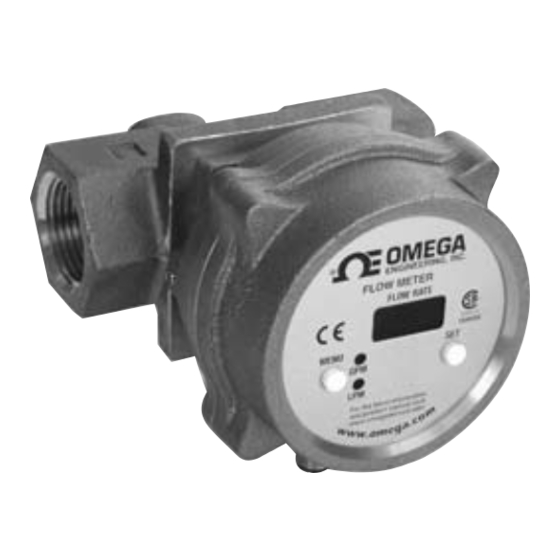
FV100-T LED Indicators The LED’s adjacent to the engineering units of GPM, LPM, F, & C have two functions. The first is to indicate the process variable being displayed and its respective engineering unit, the second to indicate alarm conditions. If temperature is being displayed, say 75 F, then 75 will appear in the display and the LED adjacent to F will be lit. -
Page 13: Installation Dimensions
Installation Dimensions INSTALLATION DRAWINGS Size 3/4" & 1" 4.54 2.27 4.04 2.08 4.19 1.78 [115mm] [58mm] [103mm] [53mm] [106mm] [45mm] 1 1/2" & 2" 6.82 3.41 4.71 2.80 4.19 1.78 [173mm] [87mm] [120mm] [71mm] [106mm] [45mm] Installation Drawings, 3/4" & 1" COVER CAN BE ROTATED TO ANY OF (4) DETENTED POSITIONS IN 90°... - Page 14 Installation Drawing, 1 1/2" & 2" COVER CAN BE ROTATED TO ANY OF (4) DETENTED POSITIONS IN 90° INCREMENTS. 1.78 [45mm] 4.19 [106mm] 3.41 2.80 1.72 [87mm] [71mm] [44mm] R4.71 [120mm] 6.16 6.82 [156mm] APPROX. SWING RADIUS [173mm] M-4117/1104 Artisan Technology Group - Quality Instrumentation ... Guaranteed | (888) 88-SOURCE | www.artisantg.com...
- Page 15 Department will issue an Authorized Return (AR) number immediately upon phone or written request. Upon examination by OMEGA, if the unit is found to be defective, it will be repaired or replaced at no charge. OMEGA’s WARRANTY does not apply to defects resulting from any action of the purchaser, including but not limited to mishandling, improper interfacing, operation outside of design limits, improper repair, or unauthorized modification.
- Page 16 Where Do I Find Everything I Need for Process Measurement and Control? OMEGA…Of Course! Shop online at omega.com TEMPERATURE Thermocouple, RTD & Thermistor Probes, Connectors, Panels & Assemblies Wire: Thermocouple, RTD & Thermistor Calibrators & Ice Point References Recorders, Controllers & Process Monitors...
Need help?
Do you have a question about the Vortex FV100 Series and is the answer not in the manual?
Questions and answers