Table of Contents

Related Manuals for Omega FMA-1600A Series


Summary of Contents for Omega FMA-1600A Series
- Page 1 User’s Guide Shop online at omega.com e-mail: info@omega.com For latest product manuals: www.omegamanual.info F F M M A A - - 1 1 6 6 0 0 0 0 A A S S e e r r i i e e s s...
- Page 2 Fax: (203) 359-7700 e-mail: info@omega.com For Other Locations Visit omega.com/worldwide The information contained in this document is believed to be correct, but OMEGA accepts no liability for any errors it contains, and reserves the right to alter specifications without notice. Introduction...
-
Page 3: Introduction
Introduction Your flow meter has a variety of innovative features: • High-accuracy performance for all your gases. Use your flow meter with any of the 98+ gases included with Gas Select™, page • 1000 readings per second guarantees high resolution data, page •... -
Page 4: Table Of Contents
Contents Introduction Serial Communication Modbus RTU Communication Quick Start Guide Establishing Communication Getting Started Polling Mode Streaming Mode Getting to Know Your Mass Flow Meter Taring The Flow Meter Display Collecting Data Status Messages Mounting Using Gas Select™ and COMPOSER™ Filters Quick Command Guide Device Ports... -
Page 5: Quick Start Guide
Quick Start Guide Setup • Connect your flow meter. Ensure that flow will pass through your device in the same direction as the arrow on the flow body (usually left to right). • Choose your engineering units. You can choose the measurement units by This M-20SLPM-D model mass selecting MAIN MENU... -
Page 6: Getting Started
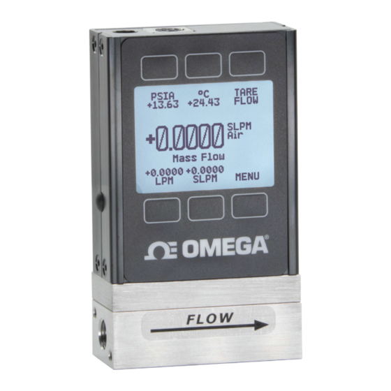
Getting Started Getting to Know Your Mass Flow Meter The Flow Meter Display The figure to the right identifies the various features of the flow meter display. Highlights pressure in the center of the device. Highlights temperature in the center of the device. ... -
Page 7: Device Ports
Device Ports Your meter has been shipped with plastic plugs fitted into its ports. To decrease the chance of contaminating the flow stream, do not remove these plugs until you are ready to install the device. Standard gas flow meters have female inlet and outlet ports. VCR®-compatible and other specialty fittings may have male connections. -
Page 8: Option: Charging Your Portable Meter
Option: Charging Your Portable Meter Portable meters’ batteries are partially charged before shipping. When fully charged, typical battery life is 18 hours with a monochrome display, or 8 hours with a TFT color display. Dimming the backlight will increase battery life. When the battery indicator displays it is completely empty, about 15 minutes of battery life remain. -
Page 9: Analog Signals
Analog Signals Primary Analog Output Signal Most devices include a primary analog output signal, which is linear over its entire range. For ranges that start at 0 Vdc, a zero-pressure condition is indicated at approximately 0.010 Vdc. Full scale pressure is indicated by the top of the range: 5 Vdc for 0–5 Vdc, 20 mA for 4–20 mA signals, and so on. -
Page 10: Displaying Live Data
Displaying Live Data Main Display The main display has these primary functions: • Displaying live temperature, pressure, and flow data • Accessing the main menu ( MENU ) or the optional totalizer ( NEXT (page • Taring the flow measurement (page This screen displays live data for all flow parameters simultaneously. -
Page 11: Option: Color Tft Display
Option: Color TFT Display Instruments ordered with a color display are functionally the same as standard backlit monochrome instruments. The color enables additional on-screen information. Multi-Color Display Indicators • GREEN: Parameter labels and adjustments associated with the button directly above or below the label are presented in green. -
Page 12: Device Information
Device Information ABOUT menu ( MENU → ABOUT ) contains useful information for setup, configuration, and troubleshooting. Basic Device Information ABOUT → About Device This includes information on the following: MODEL • : Device model • SERIAL NO : Serial number The about menu. -
Page 13: Setup
Setup Gas Selection MENU → SETUP → Active Gas Gas Select™ Most flow meters are physically calibrated at the factory using air. Gas Select™ allows you to reconfigure the flow meter to flow a different gas without any need to send it back for a physical recalibration. -
Page 14: Creating New Mixes In Composer
Creating New Mixes in COMPOSER™ SETUP → Active Gas → COMPOSER Mixes → Create Mix Give the Mix a Short and Long Name . , - DOWN will change the character. Valid characters include A–Z, 0–9, punctuation ( CANCEL and space. exits to the mix settings menu. -
Page 15: Sensor Setup
Sensor Setup MENU → SETUP → Sensor Choosing Engineering Units SETUP → Sensor → Engineering Units Changing device engineering units alters both the display and the data frame. Choose the parameter whose unit you want to change, and then select your desired engineering unit, confirming the change on the last screen. -
Page 16: Configuring Serial Communications
Configuring Serial Communications MENU → SETUP → RS-232 Serial or RS-485 Serial or Serial Comm You can operate the flow meter remotely via its data connection for easy streaming and logging of all data. Before connecting the flow meter to a computer, ensure that it is ready to communicate with your PC by checking the options in this menu. -
Page 17: Display Setup
Display Setup MENU → SETUP → Display The options in the display setup menu adjust the contrast/brightness of the display and enable screen rotation. Main Screen Options SETUP → Display → MAIN Screen Any Key Press • changes what happens when any of the parameter buttons on the main The display setup menu. -
Page 18: Serial Communication
Serial Communication Connecting your device to a computer allows you to log the data that it generates. The device communicates digitally through its communications connector and cable using a real or virtual COM port on your computer. This section of the manual shows you how to operate the flow meter using ASCII commands. -
Page 19: Polling Mode
Polling Mode Polling mode and a unit ID of is default, unless otherwise requested. Polling the device returns a single line of data for each request. To poll your device, simply enter its unit ID. [unit ID] Poll the device: Example: a... -
Page 20: Using Gas Select™ And Composer
Using Gas Select™ and COMPOSER™ To reconfigure your flow meter to flow a different gas, look up its gas number (page 24). For more information on how Gas Select™ and COMPOSER™ work, see page 13. Here are the commands: [unit ID]g[Gas Number] Choose a gas: Example 1: ag8... -
Page 21: Quick Command Guide
Quick Command Guide Serial commands are not case-sensitive. [unit ID]@=[desired ID] Change the unit ID: [unit ID]v Tare flow: Tare absolute pressure [unit ID]pc with barometer: (requires optional barometer) [unit ID] Poll the live data frame: [unit ID]@=@... -
Page 22: Troubleshooting
Troubleshooting If you run into trouble with installation or operation, get in touch with support (page 12). General Use Issue: My device does not turn on, or has trouble staying on. Action: Check power and ground connections. Please reference the technical specifications to ensure you have the proper power for your model. -
Page 23: Serial Communications
Issue: Can I use the meter with other gases? MENU SETUP Active Action: Yes! Your flow meter is designed specifically to work with many different gases. Gas Select™ ( → → ) includes up to 130 preloaded gases and gas mixes, or you can define your own using COMPOSER™ (page 13). -
Page 24: Reference Information
Reference Information Engineering Units For more information on engineering units, see page Pressure Units Flow Units Absolute or Volumetric Standard Normal Notes Barometric Gauge Notes µL ∕m SµL ∕m NµL ∕m Microliter per minute‡ Pascal mL ∕s SmL ∕s NmL ∕s Milliliter per second hPaA hPaG... -
Page 25: Gas List By Number
Gas List by Number To use any of these gases in your device, use Gas Select™ (page 13). Short Long Short Long Short Long Name Name Name Name Name Name Chloropentafluoroethane 173 HeOx80 80% O2, 20% He Air (Clean Dry) 101 R-115 (C2ClF5)2 ³... -
Page 26: Gas List By Category
Gas List by Category See previous page for Gas Select™ index numbers, or page 13 to configure these gases. Synthesis Gases Pure Non-Corrosive Gases Welding Gases Acetylene (C2H2) 40% H2, 29% CO, 20% CO2, 11% CH4 64% H2, 28% CO, 1.0% CO2, 7.0 CH4 Air (clean, dry) Argon (Ar) C-10... -
Page 27: Pinouts
Pinouts Check the calibration data sheet and pinout for your device. page 18 for additional important information about connecting your device to a computer for serial commands. 8-Pin Mini-DIN (Default) Female Connector Male Connector Pin Function Not Connected Optional: 4–20 mA primary output signal Static 5.12 Vdc Optional: secondary analog output (4–20 mA, 0–5 Vdc, 1–5 Vdc, 0–10 Vdc) or basic alarm Serial RS-232RX Input Signal... -
Page 28: 9-Pin D-Sub Connector Common Pinouts
9-Pin D-Sub Connector Common Pinouts Female Connector Male Connector DB9 (F) DB9A DB9M (M) and DB9K DB9R DB9T DB9U DB9B DB9G DB9H DB9I DB9N Current Out TX or B TX or B RX or A Analog Out 2 RX or A TX or B Power In Analog Out 2 Analog Out... -
Page 29: M12 Connector Common Pinouts
M12 Connector Common Pinouts Female Connector Male Connector Pin M12 M12MD 0–5 Vdc Output Signal Optional: 1–5 or 0–10 Vdc Not Connected Optional: 4–20 mA primary output signal Power In Static 5.12 Vdc Optional: Secondary analog output (4–20 mA, 0–5 Vdc, 1–5 Vdc, 0–10 Vdc) or basic alarm Serial RS-232 RX signal Serial RS-232 RX Signal Optional: RS-485 A... - Page 31 Department will issue an Authorized Return (AR) number immediately upon phone or written request. Upon examination by OMEGA, if the unit is found to be defective, it will be repaired or replaced at no charge. OMEGA’s WARRANTY does not apply to defects resulting from any action of the purchaser, including but not limited to mishandling, improper interfacing, operation outside of design limits, improper repair, or unauthorized modification.
- Page 32 Where Do I Find Everything I Need for Process Measurement and Control? OMEGA…Of Course! Shop online at omega.com TEMPERATURE M U Thermocouple, RTD & Thermistor Probes, Connectors, Panels & Assemblies M U Wire: Thermocouple, RTD & Thermistor M U Calibrators & Ice Point References M U Recorders, Controllers &...
Need help?
Do you have a question about the FMA-1600A Series and is the answer not in the manual?
Questions and answers