
Related Manuals for Wilo Control SC2.0-Booster


Summary of Contents for Wilo Control SC2.0-Booster
- Page 1 Pioneering for You Wilo-Control SC2.0-Booster en Installation and operating instructions · 4255846 • Ed.01/2023-09...
-
Page 3: Table Of Contents
Signal transmitters and optional modules....... 50 9 Shut-down ................ 50 Personnel qualifications............. 50 Operator responsibilities............ 50 Decommissioning.............. 50 10 Maintenance................ 51 10.1 Maintenance tasks.............. 51 11 Faults, causes and remedies............ 51 11.1 Fault indication.............. 52 11.2 Fault memory............... 52 11.3 Error codes ................ 52 Installation and operating instructions • Wilo-Control SC2.0-Booster • Ed.01/2023-09... -
Page 4: General Information
All rights reserved. Subject to change Wilo shall reserve the right to change the listed data without notice and shall not be liable for technical inaccuracies and/or omissions. The illustrations used may differ from the ori- ginal and are intended as an exemplary representation of the product. -
Page 5: Personnel Qualifications
Personnel have read and understood the installation and oper- ating instructions. • Electrical work: qualified electrician Person with appropriate technical training, knowledge and ex- perience who can identify and prevent electrical hazards. • Installation/dismantling work: qualified electrician Installation and operating instructions • Wilo-Control SC2.0-Booster • Ed.01/2023-09... -
Page 6: Electrical Work
The use of any non-original parts re- leases the manufacturer from any liability. • Disconnect the device from the mains and secure it against be- ing switched on again without authorisation. • All rotating parts must stop. Installation and operating instructions • Wilo-Control SC2.0-Booster • Ed.01/2023-09... -
Page 7: Operator Responsibilities
Wet packaging may tear. If unprotected, the product may fall on the ground and be irreparably damaged. • Carefully lift wet packaging and replace it immediately! • Clean control device. • Close housing apertures, ensuring they are sealed watertight. Installation and operating instructions • Wilo-Control SC2.0-Booster • Ed.01/2023-09... -
Page 8: Storage
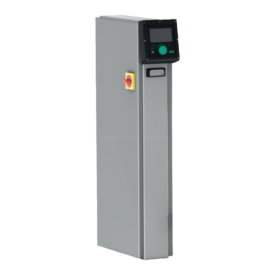
The set-up of the control device is dependent on the performance of the pumps that are to Set-up be connected as well as the version. Fig. 1: SCe Fig. 2: SC direct starting Installation and operating instructions • Wilo-Control SC2.0-Booster • Ed.01/2023-09... -
Page 9: Functional Principle
All pumps are fixed speed pumps. The pressure control is a 2-point control. Non-controlled peak-load pumps are switched on and off automatically depending on the load require- ment. Installation and operating instructions • Wilo-Control SC2.0-Booster • Ed.01/2023-09... -
Page 10: Operating Modes
Delay times can be set for activation and deactivation of the peak-load pump. • Set the delay times: Control setting→Setpoints→Delays 5.3.2 Normal operation with speed con- With the SCe version, you can choose between 2 control modes: trol – SCe • Installation and operating instructions • Wilo-Control SC2.0-Booster • Ed.01/2023-09... - Page 11 If the power requirement can no longer be met by this pump with the set speed, another pump starts when the power falls below the reference setpoint (1) and takes over the speed control. • Set speed: System→Frequency converter→Limits Fig. 6: Starting the second pump Installation and operating instructions • Wilo-Control SC2.0-Booster • Ed.01/2023-09...
- Page 12 The setpoint is dependent on the current volume flow and is between the setpoint at zero flow (2) and the reference setpoint (1) when the volume flow of the unit is at a maximum (without standby pump) (3). • Control settings→Setpoints→Setpoints 1 Installation and operating instructions • Wilo-Control SC2.0-Booster • Ed.01/2023-09...
- Page 13 The point of intersection between this pump curve and the maximum volume flow of the system (2) (here 3x6 = 18 m³/h) is used to determine the relative setpoint at zero flow (3) (here 87.5%). Link not working: See also https://app.wilo.com/Standalone/ Einstellungsoptimierer-SiBoost/Default.aspx?lang=en-GB. Fig. 9: Typical default values for the setpoint at zero flow...
- Page 14 In order to ensure that the load is distributed as evenly as possible between all pumps and to balance the running times of the pumps, various pump cycling mechanisms can be used. • The base-load pump is cycled for each requirement (after deactivation of all pumps). Installation and operating instructions • Wilo-Control SC2.0-Booster • Ed.01/2023-09...
- Page 15 Service life optimisation ensures that every pump is defined once as a standby pump. No standby pump is provided for at the factory. Standby pumps can be defined by Wilo customer service.
- Page 16 (only SCe) There is the option to choose between stopping the pumps and operating at a defined speed in the event of a communication malfunction. The setting can only be made by Wilo customer service. Pump operating mode The operating mode can be set for pumps 1 to 4 (Manual, Off, Auto).
- Page 17 Pump faults which reach the control device result in deactivation of the corresponding pump and activation of the collective fault signal. After the cause of the fault has been rec- tified, it is necessary to acknowledge the fault. Installation and operating instructions • Wilo-Control SC2.0-Booster • Ed.01/2023-09...
-
Page 18: Technical Data
Bus communication module for "BACnet IP" networks WiloCare 2.0 Connection to internet-based remote maintenance NOTICE Only one bus option can be active at any given time. Other options on request • Order accessories separately. Installation and operating instructions • Wilo-Control SC2.0-Booster • Ed.01/2023-09... -
Page 19: Installation And Electrical Connection
All cables to be connected must be inserted through threaded cable glands (FM and WM installation type) or cable inlet plates (BM installation type) into the control device and secured so that they are not under ten- sion. Installation and operating instructions • Wilo-Control SC2.0-Booster • Ed.01/2023-09... - Page 20 Fig. 12: Connecting cable shields to the earth rail Connect the cable shields with the shield clamp according to the figure. Adjust the cutting length to the width of the clamp used. Installation and operating instructions • Wilo-Control SC2.0-Booster • Ed.01/2023-09...
- Page 21 External voltage at the signal terminals will damage the product. • Do not connect any external voltage to the terminals. Connect the thermal winding contact (WSK) of the pumps to the terminals according to the circuit diagram. Installation and operating instructions • Wilo-Control SC2.0-Booster • Ed.01/2023-09...
- Page 22 Remote on/off can be connected via a potential-free contact (normally closed contact). • Connect the corresponding terminals according to the circuit diagram. • Remove the factory pre-assembled converter bridge. Contact closed Automatic ON Installation and operating instructions • Wilo-Control SC2.0-Booster • Ed.01/2023-09...
- Page 23 Connect via LAN1 bush on the printed circuit board. Observe the following points: • Interface: Ethernet RJ45 plug Installation and operating instructions • Wilo-Control SC2.0-Booster • Ed.01/2023-09...
-
Page 24: Operation
7 minutes, any unconfirmed settings will be lost. Pressing the button again opens the main menu on the display and the pump can be oper- ated from the main menu. Current faults Current alarms Installation and operating instructions • Wilo-Control SC2.0-Booster • Ed.01/2023-09... - Page 25 Pump not available Table 3: Pump status symbols Alarm active Automatic mode is switched off Base-load pump scheme Cascade active Constant speed control mode Drives are switched off External off is not allowed Installation and operating instructions • Wilo-Control SC2.0-Booster • Ed.01/2023-09...
-
Page 26: Menu Control
Confirm the selected initial settings with “End initial settings”. The display changes to the home screen when you exit the first settings menu. The unit can be operated via the main menu. Installation and operating instructions • Wilo-Control SC2.0-Booster • Ed.01/2023-09... - Page 27 In the p-c control mode, the pressure in the system is kept constant at the setpoint value, regardless of the volume flow. Fig. 17: Main screen in the p-c control mode 7.2.1 Control settings menu Installation and operating instructions • Wilo-Control SC2.0-Booster • Ed.01/2023-09...
- Page 28 With the p-v control mode, the values pressure setpoint, share at zero-flow rate and maxi- mum flow rate can be set. With the p-c control mode, only the pressure setpoint can be changed. Fig. 22: Settings→Setpoints→Setpoint 1 menu item Installation and operating instructions • Wilo-Control SC2.0-Booster • Ed.01/2023-09...
- Page 29 In the 4-20 mA current range, a conductivity test takes place. The adjustable pressure range corresponds to the range of the set pressure sensor for the output side. Fig. 26: Settings→Setpoints→External set- point menu item Installation and operating instructions • Wilo-Control SC2.0-Booster • Ed.01/2023-09...
- Page 30 Fig. 30: Settings→Control→BLP selection scheme menu item 7.2.1.4 Control settings -> Monitoring functions menu The monitoring functions ensure the operation of the units in the approved range. Fig. 31: Settings→Monitoring settings menu item Installation and operating instructions • Wilo-Control SC2.0-Booster • Ed.01/2023-09...
- Page 31 The alarm is triggered with a delay according to the set time. When the pressure has risen above the dry-run threshold again and the set restart delay has elapsed, the pumps are restarted. Fig. 36: Settings→Monitoring settings→Dry run 1/2 menu item Installation and operating instructions • Wilo-Control SC2.0-Booster • Ed.01/2023-09...
- Page 32 This mode can be helpful for systems with a break tank if the pumps have to suck in the wa- ter before pressure can be generated. Fig. 41: Settings→Additional settings→Suc- tion mode menu item Installation and operating instructions • Wilo-Control SC2.0-Booster • Ed.01/2023-09...
- Page 33 When “Constant speed” is active, automatic control is deactivated. The current range can be selected. With 4-20 mA, a conductivity test of the input is possible. Fig. 46: Settings→Additional settings→Con- stant speed 1/2 menu item Installation and operating instructions • Wilo-Control SC2.0-Booster • Ed.01/2023-09...
- Page 34 Tube filling function is active during the commissioning and restart of the unit. The pipe system can be filled with one or all pumps. Fig. 51: Settings→Additional settings→Tube filling function 1/2 menu item Installation and operating instructions • Wilo-Control SC2.0-Booster • Ed.01/2023-09...
- Page 35 Interaction / Communication menu 7.2.2.1 Interaction / Communication -> Alarms menu The menu contains the overview of current and previous alarms and warnings of the system. Fig. 54: Communication -> Alarms menu item Installation and operating instructions • Wilo-Control SC2.0-Booster • Ed.01/2023-09...
- Page 36 The type of signal can be set. It is possible to choose between an automatic reset after the external alarm has ceased or manual acknowledgement. Fig. 59: Communication→Alarms→External alarm 1/3 menu item Installation and operating instructions • Wilo-Control SC2.0-Booster • Ed.01/2023-09...
- Page 37 With a “raising” edge, the fault signal is present when the input of the external alarm is closed. The “Continue” reaction generates a pump warning. The “Stop” reaction generates a pump fault. Fig. 64: Communication→Alarms→External pump alarm 3/3 menu item Installation and operating instructions • Wilo-Control SC2.0-Booster • Ed.01/2023-09...
- Page 38 Displays the measured values in the past minutes as numerical values. Fig. 67: Communication→Diagnosis and measured values→Process values table menu item History of pump speed in the past minutes. Fig. 68: Communication→Diagnosis and measured values→Speed chart menu item Installation and operating instructions • Wilo-Control SC2.0-Booster • Ed.01/2023-09...
- Page 39 (rising edge in case of fault). Fig. 72: Communication→BMS→SxM menu item An Ethernet-based or a serial Modbus interface can be activated. Specific settings of the interface can be made. Fig. 73: Communication→BMS→Modbus menu item Installation and operating instructions • Wilo-Control SC2.0-Booster • Ed.01/2023-09...
- Page 40 The Modbus RTU option is required for the isolated interface. Fig. 77: Communication→BMS→Modbus RTU 1 menu item The “parity” (“even”, “odd”, “none”) and the number of stop bits (1 or 2) can be set. Fig. 78: Communication→BMS→Modbus RTU 2 menu item Installation and operating instructions • Wilo-Control SC2.0-Booster • Ed.01/2023-09...
- Page 41 Selection of the desired language and the setting of the country in which the system is loc- ated. Fig. 81: Communication→Display setting- s→Language menu item Fig. 82: Communication→Display settings→- Country menu item Fig. 83: Communication→Display setting- s→Language menu item Installation and operating instructions • Wilo-Control SC2.0-Booster • Ed.01/2023-09...
- Page 42 Presets for adjusting the brightness and the time without pressing a button before the dis- play dims due to lack of user input. The display does not dim when error messages are displayed. Fig. 86: Communication→Display Setting- s→LCD Settings menu item 7.2.3 Menu system Installation and operating instructions • Wilo-Control SC2.0-Booster • Ed.01/2023-09...
- Page 43 The speed can then be changed on the pump’s HMI. When communication with the control device is re-established, the control device takes over control of the pump. Fig. 91: System→Pumps→CAN fallback menu item Installation and operating instructions • Wilo-Control SC2.0-Booster • Ed.01/2023-09...
- Page 44 In the event of a sensor fault, the system can switch to emergency operation until the sensor is functional again. It is possible to run one or all pumps constantly at the set speed. Fig. 96: System→Sensors→Sensor response menu item Installation and operating instructions • Wilo-Control SC2.0-Booster • Ed.01/2023-09...
- Page 45 To avoid excessive rapid pressure changes in the installation, the speed of the speed change can be limited. The setting can be made separately for rising and falling speeds. Fig. 101: System→Frequency converter- →Ramps menu item Installation and operating instructions • Wilo-Control SC2.0-Booster • Ed.01/2023-09...
- Page 46 Information on the version of the control device and the operating unit. Fig. 105: System→Maintenance→Switchgear data 3/3 menu item Serial number of the pressure-boosting system and the corresponding article number. Fig. 106: System→Maintenance→System data menu item Installation and operating instructions • Wilo-Control SC2.0-Booster • Ed.01/2023-09...
- Page 47 Information for Wilo customer service and a freely selectable unit designation. Fig. 107: System→Maintenance→Service info menu item Selection of a memory location for up to 4 parameter sets. The selected parameter set can be given a name for easier assignment. A parameter set includes the settings from the menus, but no runtime data.
- Page 48 7.2.4 Help menu A shortened version of the manual and contact addresses from Wilo. Below is an example of a help description and the contact addresses. Fig. 112: Help menu Fig. 113: Help→Manual menu item Fig. 114: Help→Manual→Faults menu item Fig. 115: Help→Manual→Fault→E040.x menu item Fig. 116: Help→Contact menu item...
-
Page 49: User Levels
Factory setting The control system is preset at the factory. • If the factory setting is to be restored, contact Wilo customer service. • Switch on each pump briefly in “Manual operation” mode and check whether the direc- Motor direction of rotation tion of rotation of the pump in mains operation corresponds to the arrow on the pump housing. -
Page 50: Motor Protection
Disconnect all power supply lines and pull them out of the threaded cable glands. Seal the ends of the power supply cables so that no moisture can penetrate the cable. Installation and operating instructions • Wilo-Control SC2.0-Booster • Ed.01/2023-09... -
Page 51: Maintenance
• Electrical work must be carried out by a qualified electrician in accord- ance with the locally applicable regulations. • If the product is disconnected from the mains, secure it against being switched on again. Installation and operating instructions • Wilo-Control SC2.0-Booster • Ed.01/2023-09... -
Page 52: Fault Indication
Check cable connection. between control device and pump (only for SCe) Legend: * Fault must be reset manually. If there is a “W” in front of the error number, it is a warning. Installation and operating instructions • Wilo-Control SC2.0-Booster • Ed.01/2023-09... - Page 53 SCe version are described in the installation and operat- ing instructions of the pump. • If the fault cannot be rectified, contact Wilo customer service or the nearest represent- ative. Spare parts Spare parts are ordered via customer service. To avoid return queries and incorrect orders, the serial or article number must always be supplied.
- Page 54 0.157 0.130 0.113 9.0 – 11.0 0.136 9.0 – 11.0 0.098 9.0 – 11.0 0.081 9.0 – 11.0 0.071 15.0 0.087 15.0 0.063 15.0 0.052 15.0 0.045 18.5 0.059 18.5 0.043 18.5 0.035 22.0 0.046 22.0 0.033 22.0 0.027 Installation and operating instructions • Wilo-Control SC2.0-Booster • Ed.01/2023-09...
- Page 55 1, since 8 = 8. The remainder will be 0. The remaining bits 2 to 0 will thus all be 0. 14.3 ModBus: Parameter overview Holding register Name Data type Scaling and Elements Access* Supple- (protocol) unit mentary 40001 Communication profile version UINT16 0.001 31,000 40002 Wink service BOOL 31,000 Installation and operating instructions • Wilo-Control SC2.0-Booster • Ed.01/2023-09...
- Page 56 Current setpoint INT16 0.1 bar 31,000 (26) 0.1 m R (dp-v) 0.1 K R (dT-v) 0.1 °C 1/day 1/month 0.1 psi 40028 Number of pumps UINT16 31,000 (27) 40029 Maximum number of active UINT16 31,000 pumps (28) Installation and operating instructions • Wilo-Control SC2.0-Booster • Ed.01/2023-09...
- Page 57 0. Off 31,000 (43) 1. Manu 2. Auto 40062 General status BITMAP 0: SBM 31,000 (61) 1: SSM 40068 Setpoint 1 UINT16 0.1 bar 31,000 (67) 0.1 m 0.1 K 0.1 °C 0.1 psi Installation and operating instructions • Wilo-Control SC2.0-Booster • Ed.01/2023-09...
- Page 58 (96 – 97) 40099 – 40100 Total operating hours of pump UINT32 1 h 31,000 (98 – 99) 40101 – 40102 Total operating hours of pump UINT32 1 h 31,000 (100 – 101) 40103 – 40104 Total operating hours of pump UINT32 1 h 31,000 (102 – 103) Installation and operating instructions • Wilo-Control SC2.0-Booster • Ed.01/2023-09...
- Page 59 Alarm histogram index UINT16 31,000 (146) 40148 Fault number UINT16 31,000 alarm histogram (147) 40149 Fault frequency UINT16 31,000 alarm histogram (148) Legend R = read-only, RW = read- and write-accessible Installation and operating instructions • Wilo-Control SC2.0-Booster • Ed.01/2023-09...
- Page 64 Local contact at www.wilo.com/contact WILO SE Wilopark 1 44263 Dortmund Germany T +49 (0)231 4102-0 T +49 (0)231 4102-7363 wilo@wilo.com Pioneering for You www.wilo.com...
Need help?
Do you have a question about the Control SC2.0-Booster and is the answer not in the manual?
Questions and answers