
Related Manuals for Copley Controls Xenus XSL-230-40


Summary of Contents for Copley Controls Xenus XSL-230-40
- Page 1 (217) 352-9330 | Click HERE Find the Copley Controls Corp XSL-230-40 at our website:...
- Page 2 Xenus XSL™ User Guide P/N 95-00286-000 Revision 7 June 2008 Artisan Technology Group - Quality Instrumentation ... Guaranteed | (888) 88-SOURCE | www.artisantg.com...
- Page 3 Xenus XSL User Guide This page for notes. Artisan Technology Group - Quality Instrumentation ... Guaranteed | (888) 88-SOURCE | www.artisantg.com...
-
Page 4: Table Of Contents
2.13.4: Configure for Pull Up/Pull Down Resistors by Groups.................... 42 2.13.5: Programmable Input Functions ..........................42 2.14: Outputs....................................44 2.14.1: Digital Outputs ............................... 44 2.14.2: Standard Programmable Output Functions ......................44 Copley Controls Corp. Artisan Technology Group - Quality Instrumentation ... Guaranteed | (888) 88-SOURCE | www.artisantg.com... - Page 5 5.7.1: Overview.................................. 91 5.7.2: Procedure ................................91 5.7.3: Calculate.................................. 92 5.8: Amplifier Configuration ................................. 93 5.8.1: Digital Inputs................................93 5.8.2: Standard Digital Outputs............................95 Copley Controls Corp. Artisan Technology Group - Quality Instrumentation ... Guaranteed | (888) 88-SOURCE | www.artisantg.com...
- Page 6 6.8.3: Manual Phase Instructions, Resolver (-R) Xenus ....................147 6.8.4: Troubleshooting Manual Phase With Halls and Encoder..................148 6.8.5: Verify Motor Pole Count............................148 Copley Controls Corp. Artisan Technology Group - Quality Instrumentation ... Guaranteed | (888) 88-SOURCE | www.artisantg.com...
- Page 7 H.1: Amplifier Model Numbers..............................194 H.2: Accessory Model Numbers ..............................194 H.3: Order Example................................... 195 H.4: Control and Feedback Cable Color Codes ......................... 196 Copley Controls Corp. Artisan Technology Group - Quality Instrumentation ... Guaranteed | (888) 88-SOURCE | www.artisantg.com...
- Page 8 H.5.1: XTL-RA-03, XTL-RA-04 Specifications........................198 H.5.2: XTL-RA-03, XTL-RA-04 Dimensions ........................198 H.5.3: XSL-RA-01, 02 (Discontinued) Specifications......................199 H.5.4: XSL-RA-01, 02 (Discontinued) Dimensions ......................199 Copley Controls Corp. Artisan Technology Group - Quality Instrumentation ... Guaranteed | (888) 88-SOURCE | www.artisantg.com...
-
Page 9: About This Manual
Copley Indexer Program User’s Guide (describes use of Indexer Program to create motion control sequences) • Copley Controls ASCII RS-232 User Guide (describes how to send ASCII format commands over an amplifier’s serial bus to set up and control one or more amplifiers) Information on Copley Controls Software can be found at: http://www.copleycontrols.com/Motion/Products/Software/index.html... -
Page 10: Product Warnings
About this Manual Product Warnings Observe all relevant state, regional, and local safety regulations when installing and using this product. For safety and to assure compliance with documented system data, only Copley Controls Corporation should perform repairs to amplifiers. DANGER: Hazardous voltages. -
Page 11: Revision History
June 2008 17112 Changes to Control and Feedback Cable Color Codes (p. 196) Regen Resistor Specifications (p. 198). June 2008 17137 Updated Web page references. Copley Controls Corp. Artisan Technology Group - Quality Instrumentation ... Guaranteed | (888) 88-SOURCE | www.artisantg.com... -
Page 12: Introduction
CHAPTER 1: I NTRODUCTION This chapter provides an overview of Copley Controls’ Xenus amplifier. Contents include: Title Page 1.1: Amplifier ....................................12 1.2: CME 2 ....................................13 1.3: CMO/CML .................................... 13 Copley Controls Corp. Artisan Technology Group - Quality Instrumentation ... Guaranteed | (888) 88-SOURCE | www.artisantg.com... -
Page 13: Amplifier
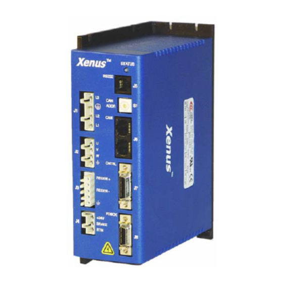
Xenus XSL User Guide 1.1: Amplifier Xenus provides 100% digital control of brushless or brush motors in an off-line powered package. It can also control a Copley Controls ServoTube motor (see ServoTube Setup, p. 84). Xenus can operate from single or three-phase mains with a continuous power output of up to 4 kW. -
Page 14: Cme 2
Introduction 1.2: CME 2 Amplifier commissioning is fast and simple using Copley Controls CME 2 software. CME 2 communicates with Xenus via an RS-232 link, and all of the operations needed to configure the amplifier are accessible through CME 2. - Page 15 Introduction Xenus XSL User Guide Copley Controls Corp. Artisan Technology Group - Quality Instrumentation ... Guaranteed | (888) 88-SOURCE | www.artisantg.com...
-
Page 16: 2: Operational Theory
2.10: Protection ................................... 36 2.11: Position and Velocity Errors..............................38 2.12: Communication .................................. 41 2.13: Inputs ....................................42 2.14: Outputs....................................44 2.15: Regen Resistor Theory............................... 47 Copley Controls Corp. Artisan Technology Group - Quality Instrumentation ... Guaranteed | (888) 88-SOURCE | www.artisantg.com... -
Page 17: Amplifier Internal Power
This prevents charging the internal capacitors to an overvoltage condition. Copley Controls Corp. Artisan Technology Group - Quality Instrumentation ... Guaranteed | (888) 88-SOURCE | www.artisantg.com... -
Page 18: 3: Power And Grounding Diagram
SIGNAL GND +24 Vdc GROUND Network +5 Vdc CONTROL ENCODER SYSTEM +5 Vdc ENABLE [IN1] CONTROL LOGIC SIGNAL GND SIGNAL GND CONTROL SIGNAL GROUND Copley Controls Corp. Artisan Technology Group - Quality Instrumentation ... Guaranteed | (888) 88-SOURCE | www.artisantg.com... -
Page 19: Synchronizing Pwm Switching Frequency
Provide a second digital encoder input to be used in the dual encoder position mode. In this mode, an encoder attached to the load provides position loop feedback, and the motor encoder or resolver provides velocity loop feedback. Copley Controls Corp. Artisan Technology Group - Quality Instrumentation ... Guaranteed | (888) 88-SOURCE | www.artisantg.com... -
Page 20: Operating Modes
2.5: Operating Modes 2.5.1: Modes and Control Loops Nesting of Control Loops and Modes Copley Controls amplifiers use up to three nested control loops - current, velocity, and position - to control a motor in three associated operating modes. Control Loops Illustration In position mode, the amplifier uses all three loops. -
Page 21: 2: Current Mode And Current Loop
Rate of change in current command. Used to limit jog moves initiated from the Control Panel Jog function in current mode, and in advanced Indexer Program functions. Copley Controls Corp. Artisan Technology Group - Quality Instrumentation ... Guaranteed | (888) 88-SOURCE | www.artisantg.com... - Page 22 CME 2 provides an Auto Tune feature, which automatically determines optimal Cp and Ci values for the motor. For more information, see Auto Tune Current Loop (p. 149). Copley Controls Corp. Artisan Technology Group - Quality Instrumentation ... Guaranteed | (888) 88-SOURCE | www.artisantg.com...
-
Page 23: 3: Velocity Mode And Velocity Loop
Fast Stop Ramp is used. For more information, see Following Error Fault Details (p. 39). Copley Controls Corp. Artisan Technology Group - Quality Instrumentation ... Guaranteed | (888) 88-SOURCE | www.artisantg.com... - Page 24 Velocity Loop Filters (p.167). Velocity Loop Outputs The output of the velocity loop is a current command used as the input to the current loop. Copley Controls Corp. Artisan Technology Group - Quality Instrumentation ... Guaranteed | (888) 88-SOURCE | www.artisantg.com...
-
Page 25: 4: Position Mode And Position Loop
Limited Position The instantaneous commanded position of the profile. Used with the actual position feedback to generate a position error. Copley Controls Corp. Artisan Technology Group - Quality Instrumentation ... Guaranteed | (888) 88-SOURCE | www.artisantg.com... -
Page 26: 5: Input Command Types
To protect against unintended response to low-level line noise or interference, the amplifier can be programmed with a “dead band” to condition the response to the input signal voltage. The Copley Controls Corp. Artisan Technology Group - Quality Instrumentation ... Guaranteed | (888) 88-SOURCE | www.artisantg.com... - Page 27 To use the analog position command as an absolute position command, the amplifier should be homed every time it is enabled. The Homing sequence may be initiated by CAN, ASCII serial, or CVM Indexer program commands. Copley Controls Corp. Artisan Technology Group - Quality Instrumentation ... Guaranteed | (888) 88-SOURCE | www.artisantg.com...
-
Page 28: 7: Pwm Input
In both formats, the amplifier can be programmed to interpret 0 or 100% duty cycle as a zero command. This provides a measure of safety in case of a controller failure or a cable break. Copley Controls Corp. Artisan Technology Group - Quality Instrumentation ... Guaranteed | (888) 88-SOURCE | www.artisantg.com... -
Page 29: 8: Digital Input
The amplifier can be set to increment position on the rising or falling edge of the signal. Stepping resolution can be programmed for electronic gearing. Copley Controls Corp. Artisan Technology Group - Quality Instrumentation ... Guaranteed | (888) 88-SOURCE | www.artisantg.com... -
Page 30: 9: Cvm Program
2.5.9: CVM Program The Copley Virtual Machine (CVM) is a software program that runs motion control programs on supported Copley Controls amplifiers. When a CVM program is running, the amplifier receives input commands from the CVM program. For more information, see the Copley Indexer Program User’s Guide. -
Page 31: Canopen Operation
The homing mode is configurable to work with a variety of combinations of encoder index, home switch, and limit switches. Copley Controls Corp. Artisan Technology Group - Quality Instrumentation ... Guaranteed | (888) 88-SOURCE | www.artisantg.com... -
Page 32: 3: Architecture
For more information on CAN addressing, see CAN Interface (p. 104). For more information on CAN communications, see Communication (p. 41). For more information on CANopen operations, see the following Copley Controls documents: • CANopen Programmer’s Manual • CML Reference Manual •... -
Page 33: Limit Switches
In addition to the response described above, any of the amplifier’s digital outputs can be configured to go active when a positive or negative limit switch is activated. For more information, Custom Output Functions (p. 45). Copley Controls Corp. Artisan Technology Group - Quality Instrumentation ... Guaranteed | (888) 88-SOURCE | www.artisantg.com... -
Page 34: Brake Operation
This sequence is not available in the current mode of operation. Instead, in current mode, the amplifier output turns off and the brake output activates immediately when the disable command is received. Copley Controls Corp. Artisan Technology Group - Quality Instrumentation ... Guaranteed | (888) 88-SOURCE | www.artisantg.com... -
Page 35: Status Indicators
A non-latched fault has occurred. Blinking red A latched fault has occurred. 20 Fast red blinks on Amplifier has reverted to boot mode. power up or reset Copley Controls Corp. Artisan Technology Group - Quality Instrumentation ... Guaranteed | (888) 88-SOURCE | www.artisantg.com... -
Page 36: 3: Can Interface Status Indicator Operation
0. A setting of 0, which is invalid, shuts down most operations on the CAN interface, and the light is shut off to indicate this status. Copley Controls Corp. Artisan Technology Group - Quality Instrumentation ... Guaranteed | (888) 88-SOURCE | www.artisantg.com... -
Page 37: Protection
PWM outputs are enabled. If the fault is latched, the fault remains active and the amplifier’s PWM outputs remain disabled until the faults are specifically cleared (as described above). Copley Controls Corp. Artisan Technology Group - Quality Instrumentation ... Guaranteed | (888) 88-SOURCE | www.artisantg.com... - Page 38 Short circuit has been removed. PWM bridge fault. Over Current (Latched) Output current I^2T limit has been Amplifier is reset and re-enabled. exceeded. *Latched by default. Copley Controls Corp. Artisan Technology Group - Quality Instrumentation ... Guaranteed | (888) 88-SOURCE | www.artisantg.com...
-
Page 39: Position And Velocity Errors
The bit is not reset until the position error remains within the tracking window for the programmed tracking time. A similar method is used to handle velocity errors. For detailed information, see Tracking Window Details (p. 40). Copley Controls Corp. Artisan Technology Group - Quality Instrumentation ... Guaranteed | (888) 88-SOURCE | www.artisantg.com... -
Page 40: 5: Following Error Fault Details
CME 2 Control Panel ( ) and press Clear Faults or Reset • clear the fault over the CANopen network or serial bus Copley Controls Corp. Artisan Technology Group - Quality Instrumentation ... Guaranteed | (888) 88-SOURCE | www.artisantg.com... -
Page 41: 6: Tracking Window Details
The following diagram illustrates the use of tracking window and time settings in velocity mode. Actual Velocity Limited Velocity ± Tracking Window Tracking Time Tracking Window Output Copley Controls Corp. Artisan Technology Group - Quality Instrumentation ... Guaranteed | (888) 88-SOURCE | www.artisantg.com... -
Page 42: Communication
CME 2 move is stopped. DANGER Failure to heed this warning can cause equipment damage, injury, or death. Copley Controls Corp. Artisan Technology Group - Quality Instrumentation ... Guaranteed | (888) 88-SOURCE | www.artisantg.com... -
Page 43: Inputs
PWM output stage will be enabled. Copley Controls Corp. Artisan Technology Group - Quality Instrumentation ... Guaranteed | (888) 88-SOURCE | www.artisantg.com... - Page 44 PWM Sync Input Receives the PWM sync output of a master amplifier. For more information, see Synchronizing PWM Switching Frequency (p. 18). (Only on high-speed inputs.) Copley Controls Corp. Artisan Technology Group - Quality Instrumentation ... Guaranteed | (888) 88-SOURCE | www.artisantg.com...
-
Page 45: Outputs
Custom Output Functions (p. 45). Program Control – Active High The state of the output is controlled by the CAN controller or the CVM control (Low) program. Copley Controls Corp. Artisan Technology Group - Quality Instrumentation ... Guaranteed | (888) 88-SOURCE | www.artisantg.com... -
Page 46: 3: Custom Output Functions
At the same time, OUT3 goes active. The under voltage condition is corrected, and: • The amplifier fault is cleared. Output stages are enabled. • OUT3 remains active. Copley Controls Corp. Artisan Technology Group - Quality Instrumentation ... Guaranteed | (888) 88-SOURCE | www.artisantg.com... - Page 47 Once settled, it remains settled until a new move is started. Copley Controls Corp. Artisan Technology Group - Quality Instrumentation ... Guaranteed | (888) 88-SOURCE | www.artisantg.com...
-
Page 48: Regen Resistor Theory
2.15.3: Regen Circuit Components The amplifier provides an internal transistor that is used in combination with an external resistor. Copley Controls supplies compatible resistors. When using a resistor acquired from another source, be sure it meets the specifications described in Regen Resistor Sizing and Configuration (p. - Page 49 Operational Theory Xenus XSL User Guide Copley Controls Corp. Artisan Technology Group - Quality Instrumentation ... Guaranteed | (888) 88-SOURCE | www.artisantg.com...
-
Page 50: Specifications
3.19: Status Indicators................................. 55 3.20: Fault Levels ..................................55 3.21: Power Dissipation ................................56 3.22: Thermal Impedance................................56 3.23: Mechanical and Environmental ............................56 3.24: Dimensions..................................57 Copley Controls Corp. Artisan Technology Group - Quality Instrumentation ... Guaranteed | (888) 88-SOURCE | www.artisantg.com... -
Page 51: Agency Approvals
* Heat sinking and/or forced air cooling required for continuous output power rating ** Consult factory for operation with inductance lower than 400 uH Copley Controls Corp. Artisan Technology Group - Quality Instrumentation ... Guaranteed | (888) 88-SOURCE | www.artisantg.com... -
Page 52: Control Loops
2 M line/sec (8 M count/sec after maximum rate quadrature) Digital Current & Velocity Command PWM frequency range 1 kHz - 100 kHz PWM minimum pulse width 220 nSec Copley Controls Corp. Artisan Technology Group - Quality Instrumentation ... Guaranteed | (888) 88-SOURCE | www.artisantg.com... -
Page 53: Analog Command Input
Current-sinking MOSFET, non-isolated 1 k pullup to internal +5 Vdc through diode Maximum Voltage +40 Vdc Maximum Sink Current Low Level Output Resistance <0.2 Function Programmable Copley Controls Corp. Artisan Technology Group - Quality Instrumentation ... Guaranteed | (888) 88-SOURCE | www.artisantg.com... -
Page 54: Brake Output
230 kHz Interpolation 1 to 256, programmable Function Incremental or analog encoder or resolver required for sinusoidal commutation and position or velocity modes of operation. Copley Controls Corp. Artisan Technology Group - Quality Instrumentation ... Guaranteed | (888) 88-SOURCE | www.artisantg.com... -
Page 55: Hall Switch Inputs
9,600 to 115,200 (defaults to 9600 on power up or reset) Data Format N, 8, 1 Flow Control None Protocol Binary or ASCII format Function Set up, control and diagnostics status Copley Controls Corp. Artisan Technology Group - Quality Instrumentation ... Guaranteed | (888) 88-SOURCE | www.artisantg.com... -
Page 56: Can Interface
Amp Over Temperature > 80 °C DC Bus Under Voltage < +60 Vdc DC Bus Over Voltage > +400 Vdc Encoder Power < +4.25 Vdc Copley Controls Corp. Artisan Technology Group - Quality Instrumentation ... Guaranteed | (888) 88-SOURCE | www.artisantg.com... -
Page 57: Power Dissipation
Environment IEC68-2: 1990 Meets U.L. Spec 94 V-0 Flammability Rating Cover Material Cooling Heat sink and/or forced air cooling required for continuous power output Copley Controls Corp. Artisan Technology Group - Quality Instrumentation ... Guaranteed | (888) 88-SOURCE | www.artisantg.com... -
Page 58: Dimensions
Xenus XSL User Guide Specifications 3.24: Dimensions Copley Controls Corp. Artisan Technology Group - Quality Instrumentation ... Guaranteed | (888) 88-SOURCE | www.artisantg.com... - Page 59 Specifications Xenus XSL User Guide Copley Controls Corp. Artisan Technology Group - Quality Instrumentation ... Guaranteed | (888) 88-SOURCE | www.artisantg.com...
-
Page 60: Wiring
4.5: Logic Supply / Brake (J4)..............................65 4.6: RS-232 Serial Communications (J5)............................. 66 4.7: CAN Bus (J6) ..................................67 Control (J7)....................................68 4.8: Motor Feedback (J8)................................72 Copley Controls Corp. Artisan Technology Group - Quality Instrumentation ... Guaranteed | (888) 88-SOURCE | www.artisantg.com... -
Page 61: General Wiring Instructions
The pin on the amplifier at J1-3 is longer than the other pins on J1, giving it a first-make, last- break action so that the amplifier chassis is never ungrounded when the mains power is connected. Copley Controls Corp. Artisan Technology Group - Quality Instrumentation ... Guaranteed | (888) 88-SOURCE | www.artisantg.com... -
Page 62: 3: Connector Locations
The housing and pin 1 of both J7 and J8 are connected to the amplifier’s chassis. 4.1.3: Connector Locations Connector locations are shown below. ™ Xenus STATUS RS232 ADDR CNTRL REGEN+ REGEN- FDBCK FDBCK +24V +24V BRAKE BRAKE Copley Controls Corp. Artisan Technology Group - Quality Instrumentation ... Guaranteed | (888) 88-SOURCE | www.artisantg.com... -
Page 63: Ac Mains (J1)
Earth Ground Keep wire length as short as * Filter Concepts 3F15 possible. Not to (or equivalent) exceed 1 Meter. used for CE compliance Copley Controls Corp. Artisan Technology Group - Quality Instrumentation ... Guaranteed | (888) 88-SOURCE | www.artisantg.com... -
Page 64: Motor (J2)
Brushless Motor Wiring Diagram Brushless Amplifier Motor J2-4 J2-3 J2-2 Case J2-1 Ground Brush Motor Wiring Diagram Brush Amplifier J2 Motor J2-4 J2-3 J2-2 Case Ground J2-1 Copley Controls Corp. Artisan Technology Group - Quality Instrumentation ... Guaranteed | (888) 88-SOURCE | www.artisantg.com... -
Page 65: Regen Resistor (J3) (Optional)
Regen Resistor Fuse type XSL-RA-01 Cooper Bussman KLM-8 or equivalent XSL-RA-02 Cooper Bussman KLM-12 or equivalent User Supplied Regen Resistor Sizing and Configuration (p. 153). Copley Controls Corp. Artisan Technology Group - Quality Instrumentation ... Guaranteed | (888) 88-SOURCE | www.artisantg.com... -
Page 66: Logic Supply / Brake (J4)
+24 Vdc Logic power supply Logic Supply / Brake Wiring Diagram Amplifier Isolated Logic Power Supply Brake +24 V J4-3 +24 Vdc Brake Power J4-2 Supply (Required) J4-1 Copley Controls Corp. Artisan Technology Group - Quality Instrumentation ... Guaranteed | (888) 88-SOURCE | www.artisantg.com... -
Page 67: Rs-232 Serial Communications (J5)
4.6: RS-232 Serial Communications (J5) Mating Connector 6-position, modular connector (RJ-11 style). Copley Controls provides a prefabricated cable and modular-to-9-pin sub-D adapter in RS-232 Serial Cable Kit, PN SER-CK. A diagram of the female connector is shown below. Pin Description... -
Page 68: Can Bus (J6)
Xenus XSL User Guide Wiring 4.7: CAN Bus (J6) Mating Connector 8-position, modular connector (RJ-45 style). Copley Controls provides the following assemblies: • Prefabricated 10 foot cable, PN XSL-NC-10 • Prefabricated 1 foot cable, PN XSL-NC-01 • Terminator Plug, PN XSL-NT A diagram of the female connector is shown below. -
Page 69: Control (J7)
10-foot cable assembly included in Connector Kit PN XSL-CA uses molded IDC style connector. NOTE: For color codes, see Control and Feedback Cable Color Codes (p. 196). Pin connections are shown here: Copley Controls Corp. Artisan Technology Group - Quality Instrumentation ... Guaranteed | (888) 88-SOURCE | www.artisantg.com... - Page 70 Signal ground reference for inputs and outputs Ref + Input Analog command positive input Ref - Input Analog command negative input IN12 Programmable Standard Group 4 Copley Controls Corp. Artisan Technology Group - Quality Instrumentation ... Guaranteed | (888) 88-SOURCE | www.artisantg.com...
- Page 71 J7-12 IN12 J7-26 Signal J7-2 Ground * Standard input R = K C = 0.033µƒ High-speed input R = 1K C = 100 pƒ Copley Controls Corp. Artisan Technology Group - Quality Instrumentation ... Guaranteed | (888) 88-SOURCE | www.artisantg.com...
- Page 72 Frame Gnd J7-1 Analog Input Wiring Diagram Amplifier Motion Controller 37.4 K Ref + VCMD + J7-24 VCMD J7-25 37.4 K Frame Gnd J7-1 Copley Controls Corp. Artisan Technology Group - Quality Instrumentation ... Guaranteed | (888) 88-SOURCE | www.artisantg.com...
-
Page 73: Motor Feedback (J8)
10 foot cable assembly included in Connector Kit PN XSL-CA uses molded IDC style connector NOTE: For color codes, see Control and Feedback Cable Color Codes (p. 196). Pin connections are shown here: Copley Controls Corp. Artisan Technology Group - Quality Instrumentation ... Guaranteed | (888) 88-SOURCE | www.artisantg.com... - Page 74 Resolver S1 Input Resolver Xenus: Resolver inputs Encoder Cos(+) In Resolver S2 Input Encoder Cos(-) In Resolver S4 Input Signal Ground Signal and +5 Vdc ground Copley Controls Corp. Artisan Technology Group - Quality Instrumentation ... Guaranteed | (888) 88-SOURCE | www.artisantg.com...
- Page 75 Hall J8-11 10 K Hall J8-12 Hall 3.3 ƒ J8-13 5 Vdc Halls J8-3 @ 400 mA Power J8-10 Frame Gnd J8-1 Case Ground Copley Controls Corp. Artisan Technology Group - Quality Instrumentation ... Guaranteed | (888) 88-SOURCE | www.artisantg.com...
- Page 76 + 5 Vdc 4.99 K pull up/pull down Motor Over Temperature Switch 10 K J8-14 Ground J8-15 74HC14 0.033 µƒ Frame Gnd J8-1 Case Ground Copley Controls Corp. Artisan Technology Group - Quality Instrumentation ... Guaranteed | (888) 88-SOURCE | www.artisantg.com...
- Page 77 Wiring Xenus XSL User Guide Copley Controls Corp. Artisan Technology Group - Quality Instrumentation ... Guaranteed | (888) 88-SOURCE | www.artisantg.com...
-
Page 78: 5: Quick Setup With Cme 2
CME 2 UICK ETUP WITH This chapter describes the general procedure for configuring and tuning an amplifier with a motor. (To copy setup data from an existing Copley Controls axis file (.ccx), skip to Quick Copy Setup Procedure (p. 128). Step Page 5.1: Warnings .................................... -
Page 79: Warnings
Do not spin motors with power off. Voltages generated by a motor can damage an amplifier. Failure to heed this warning can cause equipment damage. WARNING Copley Controls Corp. Artisan Technology Group - Quality Instrumentation ... Guaranteed | (888) 88-SOURCE | www.artisantg.com... -
Page 80: Cme 2 Installation And Serial Port Setup
If desired, delete CME2.zip to save disk space. 5.2.2.6 5.2.3: Installing CME 2 Software If installing from a CD, insert the CD (Copley Controls part number CME2). 5.2.3.1 Normally, inserting the CD causes the installation script to launch, and a CME 2 Installation screen appears. -
Page 81: 4: Serial Port Setup
Add (or click Add All to enable all available ports). To remove a port from the Selected Devices list, highlight the port name and click Remove. Copley Controls Corp. Artisan Technology Group - Quality Instrumentation ... Guaranteed | (888) 88-SOURCE | www.artisantg.com... - Page 82 Cancel to close the screen without saving changes). Review the settings. To make a change, click Back. To accept the settings, click 5.2.4.7 Finish. To close without saving changes, click Cancel. Copley Controls Corp. Artisan Technology Group - Quality Instrumentation ... Guaranteed | (888) 88-SOURCE | www.artisantg.com...
-
Page 83: Prerequisites
CME 2 could cause unexpected or uncontrolled motion. Failure to heed this warning can cause equipment damage, injury, or death. DANGER Copley Controls Corp. Artisan Technology Group - Quality Instrumentation ... Guaranteed | (888) 88-SOURCE | www.artisantg.com... -
Page 84: 2: Starting Cme 2 And Choosing An Amplifier
If you have selected an amplifier that has not been set up, the Basic Setup screen appears. If necessary, click the appropriate or amplifier in the Copley Neighborhood tree. 5.3.2.3 Copley Controls Corp. Artisan Technology Group - Quality Instrumentation ... Guaranteed | (888) 88-SOURCE | www.artisantg.com... -
Page 85: Basic Setup
Quick Setup with CME 2 Xenus XSL User Guide 5.4: Basic Setup 5.4.1: Basic Setup Screen To configure an amplifier for use with a Copley Controls ServoTube motor, skip now to 5.4.1.1 ServoTube Motor Setup (p. 185). Click the Basic Setup button ( ) to display the Basic Setup screen. - Page 86 Click OK to accept the values and write them to flash memory 5.4.1.6 to return to the Main screen without saving changes, click Cancel. Copley Controls Corp. Artisan Technology Group - Quality Instrumentation ... Guaranteed | (888) 88-SOURCE | www.artisantg.com...
-
Page 87: Motor Setup
Open. Proceed to Calculate (p. 92). to return to the Main screen without restoring motor data, click Cancel. Copley Controls Corp. Artisan Technology Group - Quality Instrumentation ... Guaranteed | (888) 88-SOURCE | www.artisantg.com... -
Page 88: 2: Rotary Motor
Range: 0.01 to 327 . Default: 0.01 Inductance Motor inductance line-to-line. Used for calculating the initial current loop tuning values. Range: see Power Output (p. 50). Copley Controls Corp. Artisan Technology Group - Quality Instrumentation ... Guaranteed | (888) 88-SOURCE | www.artisantg.com... -
Page 89: 3: Linear Motor
. Default: 0.01 Inductance Motor inductance line to line. Used for calculating the initial current loop tuning values. Range: see Power Output (p. 50). Copley Controls Corp. Artisan Technology Group - Quality Instrumentation ... Guaranteed | (888) 88-SOURCE | www.artisantg.com... -
Page 90: Feedback Setup
Primary feedback channel (J8). Position (load) encoder feedback comes through the Secondary channel (J7). The ratio of motor turns to position encoder turns is 1 to 10. Copley Controls Corp. Artisan Technology Group - Quality Instrumentation ... Guaranteed | (888) 88-SOURCE | www.artisantg.com... -
Page 91: 2: Rotary Motor Feedback Setup Options
Click Restore Default to restore default Counts/Pole. If using a brake, then proceed to Brake/Stop (Optional) (p. 91). 5.6.3.3 Else, proceed to Calculate (p. 92). Copley Controls Corp. Artisan Technology Group - Quality Instrumentation ... Guaranteed | (888) 88-SOURCE | www.artisantg.com... -
Page 92: Brake/Stop (Optional)
Range of accepted values: 0 to 100,000 rpm (mm/s for linear motor) Velocity PWM Delay Range of accepted values: 0 to 10,000 mSec Brake/Stop Response Time Copley Controls Corp. Artisan Technology Group - Quality Instrumentation ... Guaranteed | (888) 88-SOURCE | www.artisantg.com... -
Page 93: 3: Calculate
Select the file configuration by clicking Yes. The configuration will be tested later, in Auto Phase (p. 105). Click Save to Flash ( 5.7.3.4 Copley Controls Corp. Artisan Technology Group - Quality Instrumentation ... Guaranteed | (888) 88-SOURCE | www.artisantg.com... -
Page 94: Amplifier Configuration
For more information, see Debounce Time (p. 42). IN1-IN12 Select the function for the input. See Digital Input Functions (p. 94) for input function descriptions. Copley Controls Corp. Artisan Technology Group - Quality Instrumentation ... Guaranteed | (888) 88-SOURCE | www.artisantg.com... - Page 95 A low input causes the firmware to divide the level of the analog input signal by 8. PWM Sync Input PWM synchronization input, see PWM Sync Input (p. 43) PWM Sync Output (p. 44).. Copley Controls Corp. Artisan Technology Group - Quality Instrumentation ... Guaranteed | (888) 88-SOURCE | www.artisantg.com...
-
Page 96: 2: Standard Digital Outputs
Custom Digital Outputs (p. 96). Program Control High Output state controlled by CVM or CAN program Program Control Low Output state controlled by CVM or CAN program Copley Controls Corp. Artisan Technology Group - Quality Instrumentation ... Guaranteed | (888) 88-SOURCE | www.artisantg.com... -
Page 97: 3: Custom Digital Outputs
Cancel to close the screen without saving changes. 5.8.4: Save Input/Output Changes On the Input/Output screen, click Close. 5.8.4.1 On the Main screen, click Save to Flash ( 5.8.4.2 Copley Controls Corp. Artisan Technology Group - Quality Instrumentation ... Guaranteed | (888) 88-SOURCE | www.artisantg.com... -
Page 98: 5: Fault Latching
Fault Configuration screen click Cancel to restore to previous values and close the screen. On the Main screen, click Save to Flash ( 5.8.5.5 Copley Controls Corp. Artisan Technology Group - Quality Instrumentation ... Guaranteed | (888) 88-SOURCE | www.artisantg.com... -
Page 99: 6: Regen Resistor
5.8.6.2 Option Description None No external regen resistor is used. XSL-RA-01 Standard regen resistors supplied by Copley Controls. XSL-RA-02 Custom Resistor User-supplied resistor. See Regen Resistor Sizing and Configuration (p. 153). Click OK to save regen settings to flash memory and close the Regen Resistor screen 5.8.6.3... -
Page 100: 1: Analog Input
Range: -10,000 to 10,000 mV. Default: 0. For more information, see Offset (p. 26). In position mode, open the Trajectory Limits tab: 5.9.1.3 Copley Controls Corp. Artisan Technology Group - Quality Instrumentation ... Guaranteed | (888) 88-SOURCE | www.artisantg.com... - Page 101 Default: 0.5 x velocity loop Accel. Limit value. Click Close. 5.9.1.5 On the Main screen, click Save to Flash ( 5.9.1.6 Proceed to Auto Phase (p. 105). 5.9.1.7 Copley Controls Corp. Artisan Technology Group - Quality Instrumentation ... Guaranteed | (888) 88-SOURCE | www.artisantg.com...
-
Page 102: 2: Pwm Input
Invert Sign Input: In 100% duty cycle mode, inverts the polarity of the directional input. Click Close. 5.9.2.3 On the Main screen, click Save to Flash ( 5.9.2.4 Proceed to Auto Phase (p. 105). 5.9.2.5 Copley Controls Corp. Artisan Technology Group - Quality Instrumentation ... Guaranteed | (888) 88-SOURCE | www.artisantg.com... -
Page 103: 3: Digital Position Input
Output Counts: Number of Output Counts per given number of input pulses. Range: 1 to 32,767. Default: 1. Invert Command When checked, inverts commanded direction. Click the Trajectory Limits tab. 5.9.3.3 Copley Controls Corp. Artisan Technology Group - Quality Instrumentation ... Guaranteed | (888) 88-SOURCE | www.artisantg.com... - Page 104 Default: 0.5 x velocity loop Accel. Limit value. Click Close. 5.9.3.5 Click Save to Flash ( 5.9.3.6 Proceed to Auto Phase (p. 105). 5.9.3.7 Copley Controls Corp. Artisan Technology Group - Quality Instrumentation ... Guaranteed | (888) 88-SOURCE | www.artisantg.com...
-
Page 105: 4: Can Interface
OR click Cancel to close the screen without saving the changes. NOTE: CAN address and bit rate are changed only after +24 Vdc power-up or reset. Copley Controls Corp. Artisan Technology Group - Quality Instrumentation ... Guaranteed | (888) 88-SOURCE | www.artisantg.com... -
Page 106: Auto Phase
Checks the encoder or resolver and establishes proper commutation. • Checks the motor power wires for proper connection and establishes proper phasing. • Checks the Hall switches and establishes proper commutation. Copley Controls Corp. Artisan Technology Group - Quality Instrumentation ... Guaranteed | (888) 88-SOURCE | www.artisantg.com... -
Page 107: 2: Auto Phase Procedure
Trouble Shoot Motor Direction Setup (p. 109). Activate the Enable Input. 5.10.2.5 Click Next to display the Auto Phase Motor Wiring Setup screen. 5.10.2.6 Copley Controls Corp. Artisan Technology Group - Quality Instrumentation ... Guaranteed | (888) 88-SOURCE | www.artisantg.com... - Page 108 As the motor moves the Hall lines are decoded for proper commutation. If the step fails, see Trouble Shoot Halls Wiring Setup (p. 109). Copley Controls Corp. Artisan Technology Group - Quality Instrumentation ... Guaranteed | (888) 88-SOURCE | www.artisantg.com...
- Page 109 Guidelines for Choosing Auto Phase Current and Increment Rate Values (p. 109). If desired results are not obtained, proceed to Manual Phasing (p. 145). 5.10.2.15 Copley Controls Corp. Artisan Technology Group - Quality Instrumentation ... Guaranteed | (888) 88-SOURCE | www.artisantg.com...
-
Page 110: 3: Guidelines For Choosing Auto Phase Current And Increment Rate Values
Check shielding for proper grounding. 5.10.6.3 5.10.7: Other Problems If the auto phase procedure fails despite these corrective measures, see Manual Phasing (p. 145). Copley Controls Corp. Artisan Technology Group - Quality Instrumentation ... Guaranteed | (888) 88-SOURCE | www.artisantg.com... -
Page 111: Current Loop
For an introductory overview of the control loops, see Operating Modes (p. 19). NOTE: For Copley Controls digital amplifiers, the current loop gain is independent of the power supply voltage. 5.11.1: Current Loop Settings For more information, see Current Mode and Current Loop (p. -
Page 112: 2: Manually Tune Current Loop
. Then enter value directly, use mouse and arrow controls, OR use Page Up/Page Down keys to move in increments of 10. To undo a change, type Ctrl-Z. Copley Controls Corp. Artisan Technology Group - Quality Instrumentation ... Guaranteed | (888) 88-SOURCE | www.artisantg.com... - Page 113 If the amplifier is to be operated in current mode, skip the velocity and position loop 5.11.2.9 setup procedures and go to Completion Steps (p. 119). Copley Controls Corp. Artisan Technology Group - Quality Instrumentation ... Guaranteed | (888) 88-SOURCE | www.artisantg.com...
-
Page 114: Velocity Loop
Increases the resolution of the units used to express Vp and Vi, providing more precise Scalar tuning. For more information, see Velocity Loop Gains Scalar (p. 23). Filter Velocity Loop Filters (p. 167). Copley Controls Corp. Artisan Technology Group - Quality Instrumentation ... Guaranteed | (888) 88-SOURCE | www.artisantg.com... -
Page 115: 2: Manually Tune The Velocity Loop
If the amplifier is to be operated in velocity mode, skip the position loop setup 5.12.2.9 procedures and go to Completion Steps (p. 119). Copley Controls Corp. Artisan Technology Group - Quality Instrumentation ... Guaranteed | (888) 88-SOURCE | www.artisantg.com... -
Page 116: Position Loop
Width of the tracking window in counts. Tracking Window Details Window 40). Tracking Position must remain in the tracking window for Time this amount of time to be considered tracking. Copley Controls Corp. Artisan Technology Group - Quality Instrumentation ... Guaranteed | (888) 88-SOURCE | www.artisantg.com... -
Page 117: 2: Manually Tune The Position Loop
The profile may not reach constant velocity during a short move. If a following error occurs, open the CME 2 Control Panel ( ) and click Clear Faults. Copley Controls Corp. Artisan Technology Group - Quality Instrumentation ... Guaranteed | (888) 88-SOURCE | www.artisantg.com... - Page 118 Tune to multiple sets of profiles representing typical moves that might be executed in 5.13.2.6 the application. Starting with Set up a trapezoidal profile, repeat the process as needed. Copley Controls Corp. Artisan Technology Group - Quality Instrumentation ... Guaranteed | (888) 88-SOURCE | www.artisantg.com...
-
Page 119: 3: Test S-Curve Profile
Increase the move distance to produce a complete trajectory profile. Use an acceptable value the does not exceed mechanical limits of the system. Move Relative Type S-Curve Copley Controls Corp. Artisan Technology Group - Quality Instrumentation ... Guaranteed | (888) 88-SOURCE | www.artisantg.com... -
Page 120: Completion Steps
) (for backup or duplication). 5.14.2.7 Click Control Panel ( ) and then click Reset 5.14.2.8 Power-cycle the amplifier. The amplifier tuning procedure is complete. 5.14.2.9 Copley Controls Corp. Artisan Technology Group - Quality Instrumentation ... Guaranteed | (888) 88-SOURCE | www.artisantg.com... - Page 121 Quick Setup with CME 2 Xenus XSL User Guide Copley Controls Corp. Artisan Technology Group - Quality Instrumentation ... Guaranteed | (888) 88-SOURCE | www.artisantg.com...
-
Page 122: 6: Using Cme 2
6.9.1: Auto Tune Objective .............................. 149 6.9.2: Auto Tune Instructions............................149 6.10: Home Function ................................. 152 6.10.1: Overview................................152 6.10.2: Homing Functions Settings ..........................152 Copley Controls Corp. Artisan Technology Group - Quality Instrumentation ... Guaranteed | (888) 88-SOURCE | www.artisantg.com... -
Page 123: Cme 2 Overview
RAM to permanent flash data to flash memory. Restores contents amplifier’s Restore amplifier permanent flash memory to data from flash amplifier’s volatile RAM. Copley Controls Corp. Artisan Technology Group - Quality Instrumentation ... Guaranteed | (888) 88-SOURCE | www.artisantg.com... -
Page 124: 3: Main Menu Overview
Opens I/O Line States window. Help Using CME 2 with Overview of CME 2 and guide to quick setup of amplifier. Xenus Opens default web browser with relevant pages from Copley Controls’ website. Downloads Web Page Software Web Page View Release Notes Opens latest CME 2 release notes in a text viewer. -
Page 125: 4: Functional Diagram
Configure Regen Programming instructions: Regen Resistor (p. 98). Opens Fault Configuration Theory: Faults (p. 36). Configure Faults screen. Programming instructions: Fault Latching (p. 97). Copley Controls Corp. Artisan Technology Group - Quality Instrumentation ... Guaranteed | (888) 88-SOURCE | www.artisantg.com... -
Page 126: 5: Can Information And Status Bar
6.1.7.2 Click OK to close the screen and save the new name 6.1.7.3 or click Cancel to close the screen without saving the name. Copley Controls Corp. Artisan Technology Group - Quality Instrumentation ... Guaranteed | (888) 88-SOURCE | www.artisantg.com... -
Page 127: Manage Amplifier And Motor Data
From the Motor/Feedback screen, the user can save all data represented on the Motor/Feedback screen. This data is saved in a Copley Controls motor data file with a .ccm filename extension. A .ccx file can be restored to return the amplifier to a previous state or to copy settings from one amplifier to another, as described in Quick Copy Setup Procedure (p. -
Page 128: 3: Data Management Tools
Can be used before closing the Motor/Data screen to restore settings to the previously saved values. To use a data management tool, click the icon and respond to prompts. Copley Controls Corp. Artisan Technology Group - Quality Instrumentation ... Guaranteed | (888) 88-SOURCE | www.artisantg.com... -
Page 129: 4: Quick Copy Setup Procedure
Highlight the file name and then click Open to load the file data into volatile memory. On the Main screen, click Save to Flash ( ) to commit the new settings to flash 6.2.4.5 memory. Copley Controls Corp. Artisan Technology Group - Quality Instrumentation ... Guaranteed | (888) 88-SOURCE | www.artisantg.com... -
Page 130: Downloading Firmware
Extract the contents of the zip file to the same location. 6.3.1.4 The folder should now contain the files Xenus_Firmware.zip and the latest .cff file. If desired, delete Xenus_Firmware.zip to save disk space. 6.3.1.5 Copley Controls Corp. Artisan Technology Group - Quality Instrumentation ... Guaranteed | (888) 88-SOURCE | www.artisantg.com... -
Page 131: 2: Downloading Firmware To Amplifier
(Or click Cancel to close the screen without downloading new firmware.) A message window displays a series of progress messages: When the message window closes, the firmware download is complete. Copley Controls Corp. Artisan Technology Group - Quality Instrumentation ... Guaranteed | (888) 88-SOURCE | www.artisantg.com... -
Page 132: Control Panel
Indicates whether the axis has successfully been referenced (homed). The message box below the indicators displays the most recent active fault or warning message. Copley Controls Corp. Artisan Technology Group - Quality Instrumentation ... Guaranteed | (888) 88-SOURCE | www.artisantg.com... -
Page 133: 3: Monitor Functions
• Commanded Position • Bus Voltage • Velocity Error • Profile Velocity • Temperature • Following Error • Profile Acceleration • Motor Phase Angle Copley Controls Corp. Artisan Technology Group - Quality Instrumentation ... Guaranteed | (888) 88-SOURCE | www.artisantg.com... -
Page 134: 4: Control Functions
If a following error develops with Following Error Fault is disabled, motion will not stop on button release. Instead, it stops when actual position = commanded position. Copley Controls Corp. Artisan Technology Group - Quality Instrumentation ... Guaranteed | (888) 88-SOURCE | www.artisantg.com... -
Page 135: Scope Tool
As required, adjust scope tool settings. Click Record to begin trace. Click Stop Trace to stop the trace recording. Begin move with external controller. Copley Controls Corp. Artisan Technology Group - Quality Instrumentation ... Guaranteed | (888) 88-SOURCE | www.artisantg.com... -
Page 136: 2: Function Generator And Profile Tabs
Target position for Absolute move. Reverse (Relative move only.) When checked, will continuously generate forward and reverse moves of the distance specified until Stop is pressed. Repeat Copley Controls Corp. Artisan Technology Group - Quality Instrumentation ... Guaranteed | (888) 88-SOURCE | www.artisantg.com... -
Page 137: 3: Scope Settings
Actual Current Velocity Profile Velocity Voltage Analog Command Commanded Velocity Bus Voltage Limited Velocity Analog sin Input Actual Velocity Analog cos Input Velocity Error Copley Controls Corp. Artisan Technology Group - Quality Instrumentation ... Guaranteed | (888) 88-SOURCE | www.artisantg.com... - Page 138 Single Trace puts the scope in a single trace mode of operation. In this mode, the trigger is not re- armed after a trace until the user presses the Record button. Single Trace is automatically set by the generators in certain cases. Copley Controls Corp. Artisan Technology Group - Quality Instrumentation ... Guaranteed | (888) 88-SOURCE | www.artisantg.com...
- Page 139 Changing any of the preset settings de-selects the Auto Set Up feature. Copley Controls Corp. Artisan Technology Group - Quality Instrumentation ... Guaranteed | (888) 88-SOURCE | www.artisantg.com...
-
Page 140: 4: Scope Tool Controls
Velocity Loop Gains (p. 23). Velocity loop integral gain. only Current loop proportional gain. All modes Current Loop Gains (p. 21). Current loop integral gain. Copley Controls Corp. Artisan Technology Group - Quality Instrumentation ... Guaranteed | (888) 88-SOURCE | www.artisantg.com... - Page 141 For information on the Velocity Tracking options, see Position and Velocity Errors (p. 38). For information on the limits, see Velocity Loop Limits (p. 22). Copley Controls Corp. Artisan Technology Group - Quality Instrumentation ... Guaranteed | (888) 88-SOURCE | www.artisantg.com...
-
Page 142: 6: Scope Files
Using CME 2 6.5.6: Scope Files The Scope Tool can save trace data in Copley Controls scope files (.sco files) that can be opened later with the CME 2 Trace Viewer. Simultaneously, a version of the same trace is stored in a comma-separated text file (.csv) that can be opened with a spreadsheet application such as Microsoft Excel (or other programs) for mathematical analysis. -
Page 143: Error Log And Communications Log
) on the log screen. Then navigate to the appropriate folder, enter a File Name for the log, and click Save. To close the log screen, click Close. Copley Controls Corp. Artisan Technology Group - Quality Instrumentation ... Guaranteed | (888) 88-SOURCE | www.artisantg.com... -
Page 144: 2: Communications Log
Then, click Save to save the log file and close the window or click Cancel to close the window without saving the log file. Copley Controls Corp. Artisan Technology Group - Quality Instrumentation ... Guaranteed | (888) 88-SOURCE | www.artisantg.com... -
Page 145: Cme 2 Virtual Amplifier
A new virtual amplifier can be created based on a virtual amplifier template file (.ccv). Each CME 2 installation includes a set of .ccv files representing all of the Copley Controls amplifier models. Alternately, a virtual amplifier can be created based on a saved amplifier file (.ccx). -
Page 146: Manual Phasing
Verify actual position count agrees with direction of rotation: increasing counts in 6.8.2.7 forward direction and decreasing counts in reverse direction. If it does not, toggle the Encoder Invert Input box setting. Copley Controls Corp. Artisan Technology Group - Quality Instrumentation ... Guaranteed | (888) 88-SOURCE | www.artisantg.com... - Page 147 If the red indicator transition leads or lags behind the centered needle by more than 30 degrees, then try adjusting the Hall Offset in +/- 30 degree increments: Copley Controls Corp. Artisan Technology Group - Quality Instrumentation ... Guaranteed | (888) 88-SOURCE | www.artisantg.com...
-
Page 148: 3: Manual Phase Instructions, Resolver (-R) Xenus
Motor Phase Angle with Resolver Angle as shown here. Note: Motors motor manufacturers typically align the resolve in 30 degree increments, typically by applying current through a pair of motor power wires. Copley Controls Corp. Artisan Technology Group - Quality Instrumentation ... Guaranteed | (888) 88-SOURCE | www.artisantg.com... -
Page 149: 4: Troubleshooting Manual Phase With Halls And Encoder
Turn the motor shaft and count the number of distinct locking positions. 6.8.5.2 Calculate the number of poles: 6.8.5.3 Poles = Number of Positions * 2 Copley Controls Corp. Artisan Technology Group - Quality Instrumentation ... Guaranteed | (888) 88-SOURCE | www.artisantg.com... -
Page 150: Auto Tune Current Loop
Auto Tune procedure. To Change the Auto Tune Current, Press Stop, enter the new current in the Auto Tune 6.9.2.5 Current field, and then press Start. Copley Controls Corp. Artisan Technology Group - Quality Instrumentation ... Guaranteed | (888) 88-SOURCE | www.artisantg.com... - Page 151 Uses a frequency sweep to determine the small signal, current loop bandwidth. Displays the results: a set of Cp, Ci, and bandwidth value alternatives. Copley Controls Corp. Artisan Technology Group - Quality Instrumentation ... Guaranteed | (888) 88-SOURCE | www.artisantg.com...
- Page 152 Click OK to save the values as chosen, and close the Auto Tune Results window or click Cancel to close the window without saving any changes. Copley Controls Corp. Artisan Technology Group - Quality Instrumentation ... Guaranteed | (888) 88-SOURCE | www.artisantg.com...
-
Page 153: Home Function
Click OK to save the homing move settings to the amplifier’s flash memory and close 6.10.2.5 the screen. Click Cancel to close the screen without saving the settings.. 6.10.2.6 Copley Controls Corp. Artisan Technology Group - Quality Instrumentation ... Guaranteed | (888) 88-SOURCE | www.artisantg.com... -
Page 154: A: Regen Resistor Sizing And Configuration
Regen Resistor Theory (p. 47). The contents of this chapter include: Title Page A.1: Sizing a Regen Resistor..............................154 A.2: Configuring a Custom Regen Resistor ..........................158 Copley Controls Corp. Artisan Technology Group - Quality Instrumentation ... Guaranteed | (888) 88-SOURCE | www.artisantg.com... -
Page 155: A.1: Sizing A Regen Resistor
For each deceleration during the motion cycle, determine: A.1.2.1 Speed at the start of the deceleration Speed at the end of the deceleration Time over which the deceleration takes place. Copley Controls Corp. Artisan Technology Group - Quality Instrumentation ... Guaranteed | (888) 88-SOURCE | www.artisantg.com... -
Page 156: A.1.3: Calculate Energy Returned For Each Deceleration
= Energy returned to the amplifier, in joules returned = Energy returned by the deceleration, in joules = Energy dissipated by the motor, in joules motor Copley Controls Corp. Artisan Technology Group - Quality Instrumentation ... Guaranteed | (888) 88-SOURCE | www.artisantg.com... -
Page 157: A.1.6: Determine If Energy Returned Exceeds Amplifier Capacity
Choose a standard value of resistance less than the calculated value. This value must be greater than the minimum regen resistor value specified in Regen Circuit Output (p. 51). Copley Controls Corp. Artisan Technology Group - Quality Instrumentation ... Guaranteed | (888) 88-SOURCE | www.artisantg.com... -
Page 158: A.1.10: Calculate Continuous Power To Be Dissipated
= The continuous power calculated in the previous step, in watts. cont = The voltage at which the regen circuit turns on. regen Copley Controls Corp. Artisan Technology Group - Quality Instrumentation ... Guaranteed | (888) 88-SOURCE | www.artisantg.com... -
Page 159: A.2: Configuring A Custom Regen Resistor
Select Custom Resistor and then click Configure to open the Custom Regen A.2.2.2 Configuration screen. Enter a Resistance within the range described on the screen. Click Next for Step 2. A.2.2.3 Copley Controls Corp. Artisan Technology Group - Quality Instrumentation ... Guaranteed | (888) 88-SOURCE | www.artisantg.com... - Page 160 Click Finish to save the configuration to volatile and flash memory and close the A.2.2.8 screen click Prev to modify any values click Cancel to close the screen without saving any changes. Copley Controls Corp. Artisan Technology Group - Quality Instrumentation ... Guaranteed | (888) 88-SOURCE | www.artisantg.com...
- Page 161 Regen Resistor Sizing and Configuration Xenus XSL User Guide This page for notes. Copley Controls Corp. Artisan Technology Group - Quality Instrumentation ... Guaranteed | (888) 88-SOURCE | www.artisantg.com...
-
Page 162: B: I 2 T Time Limit Algorithm
This chapter describes the algorithm used to implement the I T limit. Copley Controls Corp. Artisan Technology Group - Quality Instrumentation ... Guaranteed | (888) 88-SOURCE | www.artisantg.com... -
Page 163: B.1: I 2 T Algorithm
Continuous Current Limit. If instead the commanded current is less than or equal to the Continuous Current Limit, the output current will be equal to the commanded current. Copley Controls Corp. Artisan Technology Group - Quality Instrumentation ... Guaranteed | (888) 88-SOURCE | www.artisantg.com... -
Page 164: B.1.3: I 2 T Current Limit Algorithm - Application Example
T setpoint is: T setpoint = (12 A –6 A ) * 1 S = 108 A See the example plot diagrams on the next page. Copley Controls Corp. Artisan Technology Group - Quality Instrumentation ... Guaranteed | (888) 88-SOURCE | www.artisantg.com... - Page 165 12 A. The I T Accumulator Variable value remains constant during Copley Controls Corp. Artisan Technology Group - Quality Instrumentation ... Guaranteed | (888) 88-SOURCE | www.artisantg.com...
- Page 166 The actual output current follows the current command until the I T Accumulator Variable value reaches the I T setpoint and current limiting is invoked. Copley Controls Corp. Artisan Technology Group - Quality Instrumentation ... Guaranteed | (888) 88-SOURCE | www.artisantg.com...
- Page 167 T Time Limit Algorithm Xenus XSL User Guide This page for notes. Copley Controls Corp. Artisan Technology Group - Quality Instrumentation ... Guaranteed | (888) 88-SOURCE | www.artisantg.com...
-
Page 168: Velocity Loop Filters
Bi-Quad form by entering the coefficients. The coefficients can be calculated using any commercially available math software package and entered as floating point numbers. However, due to the fixed-point representation, the numbers may be rounded. Copley Controls Corp. Artisan Technology Group - Quality Instrumentation ... Guaranteed | (888) 88-SOURCE | www.artisantg.com... - Page 169 Velocity Loop Filters Xenus XSL User Guide This page for notes. Copley Controls Corp. Artisan Technology Group - Quality Instrumentation ... Guaranteed | (888) 88-SOURCE | www.artisantg.com...
-
Page 170: D: Thermal Considerations
Contents include: D.1: Operating Temperature and Cooling Configurations ......................170 D.1.2: Heatsink and Fan Configurations .......................... 171 D.2: Heatsink Mounting Instructions ............................172 Copley Controls Corp. Artisan Technology Group - Quality Instrumentation ... Guaranteed | (888) 88-SOURCE | www.artisantg.com... -
Page 171: D.1: Operating Temperature And Cooling Configurations
Heatsink Heatsink No Heatsink No Heatsink Continuous Output Current (Adc) Continuous Output Current (Adc) The various cooling configurations are shown on the following page. Copley Controls Corp. Artisan Technology Group - Quality Instrumentation ... Guaranteed | (888) 88-SOURCE | www.artisantg.com... -
Page 172: D.1.2: Heatsink And Fan Configurations
With Fan* 4.25 in * Select a 4.25-inch square fan that supplies forced air at a minimum rate of 300 linear feet per minute Copley Controls Corp. Artisan Technology Group - Quality Instrumentation ... Guaranteed | (888) 88-SOURCE | www.artisantg.com... -
Page 173: D.2: Heatsink Mounting Instructions
NOTE: The drawing shows the standard heatsink kit (XSL-HS), but the mounting instructions given are valid for the low profile heatsink kit (XSL-HL) as well. Copley Controls Corp. Artisan Technology Group - Quality Instrumentation ... Guaranteed | (888) 88-SOURCE | www.artisantg.com... -
Page 174: E: Xenus Filter
E.3: Thermal Considerations ..............................175 E.4: XSL-FA-01 Edge Filter Dimensions............................ 176 E.5: XSL-FA-01 Edge Filter Wiring ............................177 E.6: XSL-FA-01 Edge Filter Ordering............................181 Copley Controls Corp. Artisan Technology Group - Quality Instrumentation ... Guaranteed | (888) 88-SOURCE | www.artisantg.com... -
Page 175: E.1: Overview
The differential filter increases the rise time by at least a factor of 3, substantially reducing noise in the system. Copley Controls amplifiers typically have a 150 ns-rise time (high frequency component in the MHz range). Thus, the edge filter can increase rise time to 500 ns, reducing the high frequency noise emissions by the square law. -
Page 176: E.2: Xsl-Fa-01 Edge Filter Specifications
Mount the filter on edge and mount the fan below it so that it blows up through the cover slots. There is no heatsink option for the XSL-FA-01 edge filter. Copley Controls Corp. Artisan Technology Group - Quality Instrumentation ... Guaranteed | (888) 88-SOURCE | www.artisantg.com... -
Page 177: E.4: Xsl-Fa-01 Edge Filter Dimensions
Xenus Filter Xenus XSL User Guide E.4: XSL-FA-01 Edge Filter Dimensions The following diagram shows the mounting dimensions of the XSL-FA-01 Edge Filter. Copley Controls Corp. Artisan Technology Group - Quality Instrumentation ... Guaranteed | (888) 88-SOURCE | www.artisantg.com... -
Page 178: E.5: Xsl-Fa-01 Edge Filter Wiring
J2, all of the other circuits on these connectors are mains-connected and must never be grounded. Failure to heed this warning can cause equipment damage. WARNING Copley Controls Corp. Artisan Technology Group - Quality Instrumentation ... Guaranteed | (888) 88-SOURCE | www.artisantg.com... -
Page 179: E.5.2: Connector Locations
Edge Filter J1 connects to Xenus J2. Edge Filter J2 connects to the motor. ™ Xenus STATUS RS232 ADDR CNTRL REGEN+ FROM AMPLIFIER REGEN- FDBCK FDBCK +24V +24V BRAKE BRAKE MOTOR Copley Controls Corp. Artisan Technology Group - Quality Instrumentation ... Guaranteed | (888) 88-SOURCE | www.artisantg.com... -
Page 180: E.5.3: Cable Notes
Phase V Phase V output to motor (use for DC motor connection) Phase U Phase U output to motor (use for DC motor connection) Copley Controls Corp. Artisan Technology Group - Quality Instrumentation ... Guaranteed | (888) 88-SOURCE | www.artisantg.com... -
Page 181: E.5.6: Diagram: Edge Filter Wiring With Brushless Motor
E.5.7: Diagram: Edge Filter Wiring with Brush Motor Amplifier Filter Brush J1-5 Motor J2-4 J2-4 J1-4 J2-3 J2-3 J1-3 J2-2 J2-2 J1-2 Case J2-1 J2-1 J1-1 Ground Copley Controls Corp. Artisan Technology Group - Quality Instrumentation ... Guaranteed | (888) 88-SOURCE | www.artisantg.com... -
Page 182: E.6: Xsl-Fa-01 Edge Filter Ordering
Mfr. Model No. Plug, 5 position, 5.0 mm, female Wago 721-105/026-047 XSL-FK Plug, 4 position, 5.0 mm, female Wago 721-104/026-047 Insertion / Extraction Tool Wago 231-131 Copley Controls Corp. Artisan Technology Group - Quality Instrumentation ... Guaranteed | (888) 88-SOURCE | www.artisantg.com... - Page 183 Xenus Filter Xenus XSL User Guide Copley Controls Corp. Artisan Technology Group - Quality Instrumentation ... Guaranteed | (888) 88-SOURCE | www.artisantg.com...
-
Page 184: F: Connecting For Serial Control
ONNECTING FOR ERIAL ONTROL This chapter describes how to connect one or more amplifiers for control via the RS-232 bus on one of the amplifiers. Copley Controls Corp. Artisan Technology Group - Quality Instrumentation ... Guaranteed | (888) 88-SOURCE | www.artisantg.com... -
Page 185: F.1: Single-Axis And Multi-Drop
For experimentation and simple setup and control, a telnet device such as the standard Microsoft Windows HyperTerminal can also be used to send commands in ASCII format. For more information, see Copley Controls ASCII RS-232 User Guide. The serially connected amplifier can also be used as a multi-drop gateway for access to other amplifiers linked in a series of CAN bus connections. -
Page 186: G: Servotube Motor Setup
This chapter describes the special subset of steps involved in setting up an amplifier to drive a Copley Controls ServoTube motor. Before performing the steps in this chapter, the reader should have performed a set of steps detailed in the beginning of Quick Setup with CME 2 (p. -
Page 187: G.1: Servotube Setup And Configuration
Click Yes. G.1.1.3 The software automatically sets motor and feedback options appropriate for the ServoTube motor. On the Basic Setup screen, click OK. G.1.1.4 Copley Controls Corp. Artisan Technology Group - Quality Instrumentation ... Guaranteed | (888) 88-SOURCE | www.artisantg.com... -
Page 188: G.1.2: Servotube Motor/Feedback Setup
In the Model field, choose the model number to match the ServoTube motor. G.1.2.4 Click the Feedback tab and verify the Analog Feedback settings (defaults shown G.1.2.5 below). Copley Controls Corp. Artisan Technology Group - Quality Instrumentation ... Guaranteed | (888) 88-SOURCE | www.artisantg.com... -
Page 189: G.1.3: Calculating Servotube Initial Values
Digital Inputs (p. 93) Standard Digital Outputs (p. 95) Custom Digital Outputs (p. 96) Save Input/Output Changes (p. 96) Fault latching Fault Latching (p. 97) Copley Controls Corp. Artisan Technology Group - Quality Instrumentation ... Guaranteed | (888) 88-SOURCE | www.artisantg.com... -
Page 190: G.2: Servotube Auto Phase And Manual Phase
Trouble Shoot Motor Direction Setup (p. 109). Activate the Enable Input. G.2.1.5 Click Next to display the Auto Phase Motor Wiring Setup screen. G.2.1.6 Copley Controls Corp. Artisan Technology Group - Quality Instrumentation ... Guaranteed | (888) 88-SOURCE | www.artisantg.com... - Page 191 Guidelines for Choosing Auto Phase Current and Increment Rate Values (p. 109). If desired results are not obtained, proceed to Manual Phasing (p. 145). G.2.1.12 Copley Controls Corp. Artisan Technology Group - Quality Instrumentation ... Guaranteed | (888) 88-SOURCE | www.artisantg.com...
- Page 192 Check shielding for proper grounding. Other Problems If the auto phase procedure fails despite these corrective measures, see G.2.2: ServoTube Manual Phase (p. 192). Copley Controls Corp. Artisan Technology Group - Quality Instrumentation ... Guaranteed | (888) 88-SOURCE | www.artisantg.com...
-
Page 193: G.2.2: Servotube Manual Phase
5 degrees, then try adjusting the Hall Offset in +/- 30 degree increments: G.3: Special ServoTube Setup Completion Proceed now to Current Loop (p. 110) to complete the general amplifier setup procedure. Copley Controls Corp. Artisan Technology Group - Quality Instrumentation ... Guaranteed | (888) 88-SOURCE | www.artisantg.com... -
Page 194: H: Ordering Guide And Accessories
H.5.1: XTL-RA-03, XTL-RA-04 Specifications........................198 H.5.2: XTL-RA-03, XTL-RA-04 Dimensions ........................198 H.5.3: XSL-RA-01, 02 (Discontinued) Specifications......................199 H.5.4: XSL-RA-01, 02 (Discontinued) Dimensions ......................199 Copley Controls Corp. Artisan Technology Group - Quality Instrumentation ... Guaranteed | (888) 88-SOURCE | www.artisantg.com... -
Page 195: H.1: Amplifier Model Numbers
J1-4 Tool, wire insertion and extraction Wago: 231-131 Cable assembly, control, 10 ft (3 m)* Copley Controls: XSL-CC-10 Cable assembly, feedback, 10 ft (3 m)* Copley Controls: XSL-FC-10 * For cable color codes see Control and Feedback Cable Color Codes (p. 196). -
Page 196: H.3: Order Example
Xenus Servoamplifier with standard heatsink installed XSL-CK Connector Kit with solder cup connectors CME 2 CME 2 CD SER-CK Serial Cable Kit for connecting the PC to the amplifier Copley Controls Corp. Artisan Technology Group - Quality Instrumentation ... Guaranteed | (888) 88-SOURCE | www.artisantg.com... -
Page 197: H.4: Control And Feedback Cable Color Codes
Signal Ground HS Input [IN10] White/Green Tan/Yellow Analog Ref In(+) GP Input [IN11] Green/White Yellow/Tan Analog Ref In(-) [OUT1] White/Blue Blue/White [IN12] GP Input Copley Controls Corp. Artisan Technology Group - Quality Instrumentation ... Guaranteed | (888) 88-SOURCE | www.artisantg.com... -
Page 198: H.4.3: Feedback (Xsl-Fc-10)
Resolver S3 Input No connect Orange/White Gray/White Resolver S1 Input White/Yellow Tan/Brown Resolver S2 Input Yellow/White Brown/Tan Resolver S4 Input Signal Ground White/Green Green/White Signal Ground Copley Controls Corp. Artisan Technology Group - Quality Instrumentation ... Guaranteed | (888) 88-SOURCE | www.artisantg.com... -
Page 199: H.5: Regen Resistor Specifications
Setting Default Continuous Power for a standard Copley regen resistor to a value greater than the default of 65 W may cause the resistor casing to heat to temperatures that could cause injury. If higher settings are required, contact Copley Controls customer support. WARNING Failure to heed this warning can cause equipment damage or injury. -
Page 200: H.5.3: Xsl-Ra-01, 02 (Discontinued) Specifications
Xenus XSL User Guide Ordering Guide and Accessories H.5.3: XSL-RA-01, 02 (Discontinued) Specifications Copley Controls no longer distributes XSL-RA regen resistors. Resistors with model numbers XSL-RA-01 and XSL-RA-02 have been replaced by models XTL-RA-03 and XTL-RA-04. Model Resistance Continuous Power... - Page 201 Xenus XSL™ User Guide 95-00286-000 Revision 7 June 2008 2004, 2005, 2006, 2007, 2008 Copley Controls Corporation 20 Dan Road Canton, MA 02021 USA All rights reserved Artisan Technology Group - Quality Instrumentation ... Guaranteed | (888) 88-SOURCE | www.artisantg.com...
Need help?
Do you have a question about the Xenus XSL-230-40 and is the answer not in the manual?
Questions and answers