Table of Contents
Advertisement
Advertisement
Table of Contents

Summary of Contents for Copley Controls Xenus XSL-230-36
- Page 1 Xenus™ Regeneration Guide P/N 95-00306-000 Version 1.1 November 2004...
- Page 2 Xenus Regeneration Guide This page for notes.
-
Page 3: Table Of Contents
1.3.4: Regen Resistor Configuration with CME 2 ......................... 7 Regen Resistor Sizing and Configuration ..........................9 A.1: Sizing a Regen Resistor............................... 10 A.2: Configuring a Custom Regen Resistor ..........................14 A.2.1: Regen Configuration Objective and Warning......................14 A.2.2: Regen Configuration Instructions ..........................14 Copley Controls Corp. - Page 4 Table of Contents Xenus Regeneration Guide This page for notes. Copley Controls Corp.
-
Page 5: About This Guide
We reserve the right to modify our products. The information in this document is subject to change without notice and does not represent a commitment by Copley Controls Corporation. Copley Controls Corporation assumes no responsibility for any errors that may appear in this document. -
Page 6: Product Warnings
Xenus Regeneration Guide Product Warnings Observe all relevant state, regional, and local safety regulations when installing and using this product. For safety and to assure compliance with documented system data, only Copley Controls Corporation should perform repairs to amplifiers. DANGER: Hazardous voltages. -
Page 7: 1: Regen Resistors For Xenus
ESISTORS FOR ENUS This chapter provides an overview of regeneration and using regen resistors with Xenus. The contents of this chapter include: Title Page 1.1: Regen Resistor Theory................................2 1.2: Regen Specifications................................2 1.3: Regen Circuit Wiring................................4 Copley Controls Corp. -
Page 8: Regen Resistor Theory
57 joules 240 Vac 32 joules 1.2.2: Copley Standard Regen Resistor Specifications Model Resistance Continuous Power Peak Power For Use With XSL-RA-01 30 ohms 167 W 5 kW XSL-230-18 XSL-RA-02 15 ohms 200 W 10 kW XSL-230-36 XSL-230-40 Copley Controls Corp. -
Page 9: 3: Regen Dimensions
Xenus Regeneration Guide Regen Resistor Sizing and Configuration 1.2.3: Regen Dimensions The following diagram describes the mounting dimensions (in inches) of both of the Copley- supplied resistors. 9.25 4.125 .244 TYP 2X 2.75 .50 TYP .25 TYP Copley Controls Corp. -
Page 10: Regen Circuit Wiring
With the exception of the ground pins on J1, J2, and J3, all of the other circuits on these connectors are mains-connected and must never be grounded. Failure to heed this warning can cause equipment damage. WARNING Copley Controls Corp. -
Page 11: 2: Connector Locations
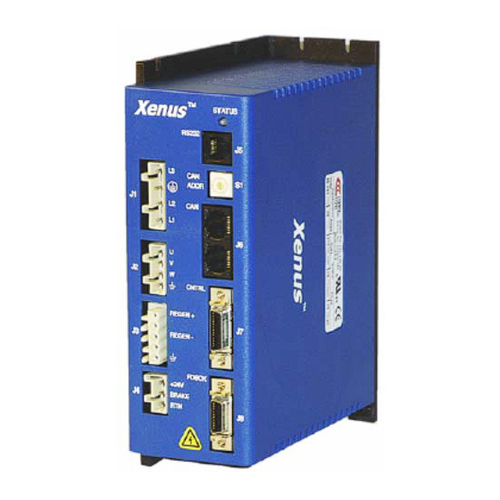
Xenus Regeneration Guide Regen Resistor Sizing and Configuration 1.3.2: Connector Locations Connector locations are shown below. The regen connector is J3. ™ Xenus STATUS RS232 ADDR CNTRL REGEN+ REGEN- FDBCK FDBCK +24V +24V BRAKE BRAKE Copley Controls Corp. -
Page 12: 3: Regen Resistor (J3) Wiring
J3-1 J3-2 Regen J3-3 J3-4 J3-5 DC Bus Regen Resistor Fusing Recommended Fuses: Regen Resistor Fuse type XSL-RA-01 Cooper Bussman KLM-8 or equivalent XSL-RA-02 Cooper Bussman KLM-12 or equivalent User Supplied Regen Resistor Sizing and Configuration (p. Copley Controls Corp. -
Page 13: 4: Regen Resistor Configuration With Cme 2
Option Description None No external regen resistor is used. XSL-RA-01 Standard regen resistors supplied by Copley Controls. XSL-RA-02 Custom Resistor User-supplied resistor. See Regen Resistor Sizing and Configuration (p. Click OK to save regen settings to flash memory and close the Regen Resistor screen 1.3.4.3... - Page 14 Regen Resistor Sizing and Configuration Xenus Regeneration Guide This page for notes. Copley Controls Corp.
-
Page 15: A: Regen Resistor Sizing And Configuration
This chapter describes the formulas used to determine if a regen resistor is required and what the optimal resistor characteristics would be for a given application. The contents of this chapter include: Title Page A.1: Sizing a Regen Resistor............................... 10 A.2: Configuring a Custom Regen Resistor ..........................14 Copley Controls Corp. -
Page 16: A.1: Sizing A Regen Resistor
A.1.2: Observe the Properties of Each Deceleration During a Complete Cycle of Operation For each deceleration during the motion cycle, determine: A.1.2.1 Speed at the start of the deceleration Speed at the end of the deceleration Time over which the deceleration takes place. Copley Controls Corp. - Page 17 Calculate the amount of energy that will be returned to the amplifier for each deceleration using the following formula. returned motor Where: = Energy returned to the amplifier, in joules returned = Energy returned by the deceleration, in joules = Energy dissipated by the motor, in joules motor Copley Controls Corp.
- Page 18 = The voltage at which the regen circuit turns on. regen Choose a standard value of resistance less than the calculated value. This value must be greater than the minimum regen resistor value specified in Amplifier Regen Circuit Output Specifications Copley Controls Corp.
- Page 19 Where: = The minimum continuous current rating the fuse requires in amps. cont = The continuous power calculated in the previous step, in watts. cont = The voltage at which the regen circuit turns on. regen Copley Controls Corp.
-
Page 20: A.2: Configuring A Custom Regen Resistor
) to open the Regen Resistor A.2.2.1 screen. Select Custom Resistor and then click Configure to open the Custom Regen A.2.2.2 Configuration screen. Enter a Resistance within the range described on the screen. Click Next for Step 2. A.2.2.3 Copley Controls Corp. - Page 21 A.2.2.6 Review the configuration. A.2.2.7 Click Finish to save the configuration to volatile and flash memory and close the A.2.2.8 screen click Prev to modify any values click Cancel to close the screen without saving any changes. Copley Controls Corp.
- Page 22 Xenus™ Regeneration Guide P/N 95-00306-000 Version 1.1 November 2004 2003, 2004 Copley Controls Corporation 20 Dan Road Canton, MA 02021 USA All rights reserved...


Need help?
Do you have a question about the Xenus XSL-230-36 and is the answer not in the manual?
Questions and answers