Table of Contents
Advertisement
Quick Links
Advertisement
Table of Contents

Related Manuals for Copley Controls Xenus XSL


Summary of Contents for Copley Controls Xenus XSL
- Page 1 Artisan Technology Group is your source for quality new and certified-used/pre-owned equipment SERVICE CENTER REPAIRS WE BUY USED EQUIPMENT • FAST SHIPPING AND DELIVERY Experienced engineers and technicians on staff Sell your excess, underutilized, and idle used equipment at our full-service, in-house repair center We also offer credit for buy-backs and trade-ins •...
- Page 2 Xenus XSL™ User Guide P/N 95-00286-000 Revision 7 June 2008 Artisan Technology Group - Quality Instrumentation ... Guaranteed | (888) 88-SOURCE | www.artisantg.com...
- Page 3 Xenus XSL User Guide This page for notes. Artisan Technology Group - Quality Instrumentation ... Guaranteed | (888) 88-SOURCE | www.artisantg.com...
-
Page 4: Table Of Contents
2.13.4: Configure for Pull Up/Pull Down Resistors by Groups.................... 42 2.13.5: Programmable Input Functions ..........................42 2.14: Outputs....................................44 2.14.1: Digital Outputs ............................... 44 2.14.2: Standard Programmable Output Functions ......................44 Copley Controls Corp. Artisan Technology Group - Quality Instrumentation ... Guaranteed | (888) 88-SOURCE | www.artisantg.com... - Page 5 Table of Contents Xenus XSL User Guide 2.14.3: Custom Output Functions ............................45 2.15: Regen Resistor Theory............................... 47 2.15.1: Regeneration ................................. 47 2.15.2: Regen Resistor ..............................47 2.15.3: Regen Circuit Components ............................ 47 2.15.4: Regen Circuit Protections ............................47 2.15.5: Configurable Custom Resistor ..........................47 Specifications ....................................
- Page 6 Xenus XSL User Guide Table Of Contents 5.8.3: Custom Digital Outputs............................96 5.8.4: Save Input/Output Changes............................. 96 5.8.5: Fault Latching ................................97 5.8.6: Regen Resistor ................................ 98 5.9: Command Input..................................98 5.9.1: Analog Input ................................99 5.9.2: PWM Input................................101 5.9.3: Digital Position Input ..............................
- Page 7 Table of Contents Xenus XSL User Guide 6.9: Auto Tune Current Loop ..............................149 6.9.1: Auto Tune Objective .............................. 149 6.9.2: Auto Tune Instructions............................149 6.10: Home Function ................................. 152 6.10.1: Overview................................152 6.10.2: Homing Functions Settings ..........................152 Regen Resistor Sizing and Configuration ..........................153 A.1: Sizing a Regen Resistor..............................
- Page 8 Xenus XSL User Guide Table Of Contents H.4.1: Wire Description Nomenclature..........................196 H.4.2: Control Cable (XSL-CC-10) ........................... 196 H.4.3: Feedback (XSL-FC-10) ............................197 H.5: Regen Resistor Specifications ............................198 H.5.1: XTL-RA-03, XTL-RA-04 Specifications........................198 H.5.2: XTL-RA-03, XTL-RA-04 Dimensions ........................198 H.5.3: XSL-RA-01, 02 (Discontinued) Specifications......................
-
Page 9: About This Manual
Copley Indexer Program User’s Guide (describes use of Indexer Program to create motion control sequences) • Copley Controls ASCII RS-232 User Guide (describes how to send ASCII format commands over an amplifier’s serial bus to set up and control one or more amplifiers) Information on Copley Controls Software can be found at: http://www.copleycontrols.com/Motion/Products/Software/index.html... -
Page 10: Product Warnings
About this Manual Product Warnings Observe all relevant state, regional, and local safety regulations when installing and using this product. For safety and to assure compliance with documented system data, only Copley Controls Corporation should perform repairs to amplifiers. DANGER: Hazardous voltages. -
Page 11: Revision History
About this Manual Xenus XSL User Guide Revision History Revision Date DECO # Comments June 2003 Initial publication. July 2003 New CAN termination plug requires documentation changes in CAN Interface (p. 55) CAN Bus (J6) (p. 67). April 2005 Support for resolvers and dual feedback configurations, and emulated digital encoder output source. -
Page 12: Introduction
CHAPTER 1: I NTRODUCTION This chapter provides an overview of Copley Controls’ Xenus amplifier. Contents include: Title Page 1.1: Amplifier ....................................12 1.2: CME 2 ....................................13 1.3: CMO/CML .................................... 13 Copley Controls Corp. Artisan Technology Group - Quality Instrumentation ... Guaranteed | (888) 88-SOURCE | www.artisantg.com... -
Page 13: Amplifier
Xenus XSL User Guide 1.1: Amplifier Xenus provides 100% digital control of brushless or brush motors in an off-line powered package. It can also control a Copley Controls ServoTube motor (see ServoTube Setup, p. 84). Xenus can operate from single or three-phase mains with a continuous power output of up to 4 kW. -
Page 14: Cme 2
Introduction 1.2: CME 2 Amplifier commissioning is fast and simple using Copley Controls CME 2 software. CME 2 communicates with Xenus via an RS-232 link, and all of the operations needed to configure the amplifier are accessible through CME 2. - Page 15 Introduction Xenus XSL User Guide Copley Controls Corp. Artisan Technology Group - Quality Instrumentation ... Guaranteed | (888) 88-SOURCE | www.artisantg.com...
-
Page 16: 2: Operational Theory
2.10: Protection ................................... 36 2.11: Position and Velocity Errors..............................38 2.12: Communication .................................. 41 2.13: Inputs ....................................42 2.14: Outputs....................................44 2.15: Regen Resistor Theory............................... 47 Copley Controls Corp. Artisan Technology Group - Quality Instrumentation ... Guaranteed | (888) 88-SOURCE | www.artisantg.com... -
Page 17: Amplifier Internal Power
Operational Theory Xenus XSL User Guide 2.1: Amplifier Internal Power Power distribution within Xenus is divided into three sections: +24 Vdc, logic/signal, and high voltage. Each is isolated from the other. 2.1.1: Logic/Signal Power An internal DC/DC converter operates from the +24 Vdc Logic Supply input and creates the required logic/signal operating voltages, the isolated voltages required for the high-voltage control circuits, and a +5 Vdc supply for powering the motor encoder and Hall circuits. -
Page 18: 3: Power And Grounding Diagram
Xenus XSL User Guide Operational Theory 2.1.3: Power and Grounding Diagram SHIELD AMPLIFIER CHASSIS REGEN(+) REGEN(-) 1760 RF DC BUSS(+) MOTOR MAINS INVERTER DC BUSS(-) FRAME CASE (SAFETY) GROUND STAGE +24 Vdc CONTROL POWER ISOLATION BARRIER BRAKE SHIELD BRAKE +5 Vdc @... -
Page 19: Synchronizing Pwm Switching Frequency
Operational Theory Xenus XSL User Guide 2.2: Synchronizing PWM Switching Frequency In some situations, such as when sampling small analog signals, it is desirable to synchronize the PWM switching frequency among multiple amplifiers. In these cases, one amplifier serves as a master for one or more slave amplifiers. -
Page 20: Operating Modes
2.5: Operating Modes 2.5.1: Modes and Control Loops Nesting of Control Loops and Modes Copley Controls amplifiers use up to three nested control loops - current, velocity, and position - to control a motor in three associated operating modes. Control Loops Illustration In position mode, the amplifier uses all three loops. -
Page 21: 2: Current Mode And Current Loop
Operational Theory Xenus XSL User Guide 2.5.2: Current Mode and Current Loop Current Loop Diagram As shown below, the “front end” of the current loop is a limiting stage. The limiting stage accepts a current command, applies limits, and passes a limited current command to the summing junction. - Page 22 Xenus XSL User Guide Operational Theory Current Loop Gains The current loop uses these gains: Gain Description Cp - Current loop proportional The current error (the difference between the actual and the limited commanded current) is multiplied by this value. The primary effect of this gain is to increase bandwidth (or decrease the step-response time) as the gain is increased.
-
Page 23: 3: Velocity Mode And Velocity Loop
Operational Theory Xenus XSL User Guide 2.5.3: Velocity Mode and Velocity Loop Velocity Loop Diagram As shown below, the velocity loop limiting stage accepts a velocity command, applies limits, and passes a limited velocity command to the input filter. The filter then passes a velocity command to the summing junction. - Page 24 Xenus XSL User Guide Operational Theory Diagram: Effects of Limits on Velocity Command The following diagram illustrates the effects of the velocity loop limits. Limited Velocity Commanded Velocity Vel Limit Accel Limit Decel Limit Velocity Loop Gains The velocity loop uses these gains:...
-
Page 25: 4: Position Mode And Position Loop
Operational Theory Xenus XSL User Guide 2.5.4: Position Mode and Position Loop Position Loop Diagram The amplifier receives position commands from the digital or analog command inputs, over the CAN interface or serial bus, or from the CVM Control Program. When using the digital or analog inputs, the amplifier's internal trajectory generator calculates a trapezoidal motion profile based on the trajectory limit parameters. -
Page 26: 5: Input Command Types
Xenus XSL User Guide Operational Theory Position Loop Gains The following gains are used by the position loop to calculate the velocity command: Gain Description Pp - Position loop proportional The loop calculates the position error as the difference between the actual and limited position values. - Page 27 Operational Theory Xenus XSL User Guide amplifier treats anything within the dead band ranges as zero, and subtracts the dead band value from all other values. For instance, with a dead band of 100 mV, the amplifier ignores signals between –100 mV and +100 mV, and treats 101 mV as 1 mV, 200 mV as 100 mV, and so on.
-
Page 28: 7: Pwm Input
Xenus XSL User Guide Operational Theory 2.5.7: PWM Input Two Formats The amplifier can accept a pulse width modulated signal (PWM) signal to provide a current command in current mode and a velocity command in velocity mode. The PWM input can be programmed for two formats: 50% duty cycle (one-wire) and 100% duty cycle (two-wire). -
Page 29: 8: Digital Input
Operational Theory Xenus XSL User Guide 2.5.8: Digital Input Three Formats In position mode, the amplifier can accept position commands via two digital inputs, using one of these signal formats: pulse and direction, count up/count down, and quadrature. In all three formats, the amplifier can be configured to invert the command. -
Page 30: 9: Cvm Program
2.5.9: CVM Program The Copley Virtual Machine (CVM) is a software program that runs motion control programs on supported Copley Controls amplifiers. When a CVM program is running, the amplifier receives input commands from the CVM program. For more information, see the Copley Indexer Program User’s Guide. -
Page 31: Canopen Operation
Operational Theory Xenus XSL User Guide 2.6: CANopen Operation 2.6.1: CAN Network and CANopen Profiles for Motion In position mode, the amplifier can take instruction over a two-wire Controller Area Network (CAN). CAN specifies the data link and physical connection layers of a fast, reliable network. -
Page 32: 3: Architecture
For more information on CAN addressing, see CAN Interface (p. 104). For more information on CAN communications, see Communication (p. 41). For more information on CANopen operations, see the following Copley Controls documents: • CANopen Programmer’s Manual • CML Reference Manual •... -
Page 33: Limit Switches
Operational Theory Xenus XSL User Guide 2.7: Limit Switches 2.7.1: Use Digital Inputs to Connect Limit Switches Limit switches help protect the motion system from unintended travel to the mechanical limits. Any of the digital inputs 2-12 can be can be programmed as positive or negative limit switch inputs. -
Page 34: Brake Operation
Xenus XSL User Guide Operational Theory 2.8: Brake Operation 2.8.1: Digital Output Controls Brake Many control systems employ a brake to hold the axis when the amplifier is disabled. Digital output 4 (OUT4) is designed specifically for a brake output. (Other outputs can be used for brake control, but OUT4 is recommended.) Unlike the other outputs, OUT4 is optically isolated from the control... -
Page 35: Status Indicators
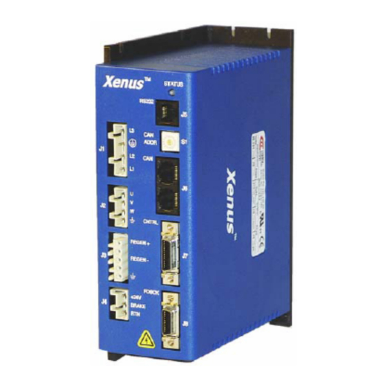
Operational Theory Xenus XSL User Guide 2.9: Status Indicators 2.9.1: Amplifier and CAN Interface Status Indicators The amplifier’s status indicator is a bicolor LED labeled STATUS on the amplifier front panel. The CAN interface status indicator is a bicolor LED labeled CAN. Locations are shown below. -
Page 36: 3: Can Interface Status Indicator Operation
Xenus XSL User Guide Operational Theory 2.9.3: CAN Interface Status Indicator Operation The amplifier status indicator color/blink codes comply with CAN Indicator Specification 303-3 as described below. Note that green and red codes are often interlaced, each indicating a different set of conditions. -
Page 37: Protection
Operational Theory Xenus XSL User Guide 2.10: Protection 2.10.1: Faults Overview Xenus detects and responds to a set of conditions regarded as faults, such as amplifier over temperature and excessive following error. When any fault occurs, with the exception of a following error, the amplifier’s PWM output stage is disabled, the fault type is recorded in the... - Page 38 Xenus XSL User Guide Operational Theory Fault Descriptions The set of possible faults is described below. For details on limits and ranges, see Fault Levels (p. 55). Fault Description Fault Occurs When… Fault is Corrected When… *Amplifier Over Temperature Amplifier's internal power module...
-
Page 39: Position And Velocity Errors
Operational Theory Xenus XSL User Guide 2.11: Position and Velocity Errors 2.11.1: Error-Handling Methods In position mode, any difference between the limited position output of the trajectory generator and the actual motor position is a position error. The amplifier’s position loop uses complementary methods for handling position errors: following error fault, following error warning, and a position- tracking window. -
Page 40: 5: Following Error Fault Details
Xenus XSL User Guide Operational Theory 2.11.5: Following Error Fault Details Position Error Reaches Fault Level As described earlier, position error is the difference between the limited position output of the trajectory generator and the actual position. When position error reaches the programmed Following Error Fault level, the amplifier faults (unless the following error fault is disabled.) As with... -
Page 41: 6: Tracking Window Details
Operational Theory Xenus XSL User Guide 2.11.6: Tracking Window Details Proper Tracking Over Time As described earlier, position error is the difference between the limited position output of the trajectory generator and the actual position. Velocity error is the difference between commanded and actual velocity. -
Page 42: Communication
Xenus XSL User Guide Operational Theory 2.12: Communication 2.12.1: Communication Interfaces As described below, the amplifier features two communication interfaces, each used for different purposes. Interface Description RS-232 port The amplifier features a three-wire RS-232 port. CME 2 software communicates with the amplifier using a binary protocol over this link for commissioning, adjustments, and diagnostics. -
Page 43: Inputs
Operational Theory Xenus XSL User Guide 2.13: Inputs 2.13.1: Digital Inputs The amplifier has twelve digital inputs (IN1-IN12). Eleven of them appear on the control connector. IN5 appears on the feedback connector, and is intended for the motor over temperature switch (although it can be programmed for any function). - Page 44 Xenus XSL User Guide Operational Theory General Programmable Input Functions Other inputs, depending on the selected mode of operation, may also have pre-defined functions, as described in Mode-Dependant Dedicated Inputs 70). The remaining inputs can be programmed to functions listed below.
-
Page 45: Outputs
Operational Theory Xenus XSL User Guide 2.14: Outputs 2.14.1: Digital Outputs The amplifier has four programmable digital outputs. Three of the outputs (OUT1 - 3) are general- purpose outputs. The fourth (OUT4) is specifically designed as a brake output but can be programmed to perform any of the functions. -
Page 46: 3: Custom Output Functions
Xenus XSL User Guide Operational Theory 2.14.3: Custom Output Functions Any of the amplifier’s digital outputs can be set up in a custom configuration to respond to a combination of events including faults, warnings, and status indications. The output goes active when one or more of the selected events take place. - Page 47 Operational Theory Xenus XSL User Guide Custom Output Warning Functions A custom output can be configured to go active when the amplifier issues any of the following warnings. Event Description Current Output Limited The current output is being limited by the I T algorithm or a latched current fault has occurred.
-
Page 48: Regen Resistor Theory
2.15.3: Regen Circuit Components The amplifier provides an internal transistor that is used in combination with an external resistor. Copley Controls supplies compatible resistors. When using a resistor acquired from another source, be sure it meets the specifications described in Regen Resistor Sizing and Configuration (p. - Page 49 Operational Theory Xenus XSL User Guide Copley Controls Corp. Artisan Technology Group - Quality Instrumentation ... Guaranteed | (888) 88-SOURCE | www.artisantg.com...
-
Page 50: Specifications
3.19: Status Indicators................................. 55 3.20: Fault Levels ..................................55 3.21: Power Dissipation ................................56 3.22: Thermal Impedance................................56 3.23: Mechanical and Environmental ............................56 3.24: Dimensions..................................57 Copley Controls Corp. Artisan Technology Group - Quality Instrumentation ... Guaranteed | (888) 88-SOURCE | www.artisantg.com... -
Page 51: Agency Approvals
Specifications Xenus XSL User Guide 3.1: Agency Approvals • CE Compliance: 89/336/EEC Electromagnetic EN 55011 Compatibility EN 550082-1 98/37/EC Safety of Machinery EN 60204-1 • UL 508C 3.2: Power Input Model XSL-230-18 XSL-230-36 XSL-230-40 XSL-230-18-R XSL-230-36-R XSL-230-40-R Mains Voltage 100 - 240 Vac 1 Ø... -
Page 52: Control Loops
Xenus XSL User Guide Specifications 3.4: Control Loops Type Current Velocity 100% digital. Position Sampling rate (time) Current 15 kHz (67 Rs) Velocity 3 kHz (333 Rs) Position 3 kHz (333 Rs) Current Loop Small Signal Bandwidth > 2 kHz... -
Page 53: Analog Command Input
Specifications Xenus XSL User Guide 3.7: Analog Command Input Channels Type Differential, non-isolated Measurement Range ±10 Vdc Maximum Voltage Differential ±10 Vdc Input to Ground ±10 Vdc Input Impedance 66 k Resolution 12 Bit Bandwidth 7 kHz 67 µSec Scan Time... -
Page 54: Brake Output
Xenus XSL User Guide Specifications 3.10: Brake Output Channels Type Current-sinking MOSFET, optically isolated from control/logic ground. Referenced to +24 Vdc logic supply. Internal fly back diode to +24 Vdc. Maximum Sink Current Low Level Output Resistance <0.2 Function Primary function is brake control. -
Page 55: Hall Switch Inputs
Specifications Xenus XSL User Guide 3.14: Hall Switch Inputs Channels Type 74HC14 Schmitt trigger w/ RC Filter 10 k pull up resistor to internal +5 Vdc Input Voltage Range 0 Vdc - +28 Vdc Low Level Input Voltage < +1.35 Vdc High Level Input Voltage >... -
Page 56: Can Interface
Xenus XSL User Guide Specifications 3.18: CAN Interface Channels Connectors 2 eight-position modular (RJ-45 style) wired as per CAN Cia DR-303-1, V1.1 One connector for signal input. Second connector for daisy chaining to next node. Signals CAN H, CAN L, CAN Gnd... -
Page 57: Power Dissipation
Specifications Xenus XSL User Guide 3.21: Power Dissipation Model: XSL-230-18 XSL-230-36 XSL-230-40 XSL-230-18-R XSL-230-36-R XSL-230-40-R Output Power Mains Voltage Maximum 120 Vac 30 W 55 W 92 W Continuous 240 Vac 40 W 75 W 120 W Power Dissipation 230 VAC... -
Page 58: Dimensions
Xenus XSL User Guide Specifications 3.24: Dimensions Copley Controls Corp. Artisan Technology Group - Quality Instrumentation ... Guaranteed | (888) 88-SOURCE | www.artisantg.com... - Page 59 Specifications Xenus XSL User Guide Copley Controls Corp. Artisan Technology Group - Quality Instrumentation ... Guaranteed | (888) 88-SOURCE | www.artisantg.com...
-
Page 60: Wiring
4.5: Logic Supply / Brake (J4)..............................65 4.6: RS-232 Serial Communications (J5)............................. 66 4.7: CAN Bus (J6) ..................................67 Control (J7)....................................68 4.8: Motor Feedback (J8)................................72 Copley Controls Corp. Artisan Technology Group - Quality Instrumentation ... Guaranteed | (888) 88-SOURCE | www.artisantg.com... -
Page 61: General Wiring Instructions
Wiring Xenus XSL User Guide 4.1: General Wiring Instructions 4.1.1: Electrical Codes and Warnings Be sure that all wiring complies with the National Electrical Code (NEC) or its national equivalent, and all prevailing local codes. DANGER: Hazardous voltages. Exercise caution when installing and adjusting. -
Page 62: 3: Connector Locations
Xenus XSL User Guide Wiring J2 and J3 Grounds The ground terminals at J2-1 and J3-5 also connect to the amplifier chassis. Motor cases can be safety-grounded either at the motor, by earthing the frame, or by a grounding conductor in the motor cable that connects to J2-1. This conductor should be of the same gauge as the other motor phase conductors. -
Page 63: Ac Mains (J1)
Wiring Xenus XSL User Guide 4.2: AC Mains (J1) Mating Connector Description Euro-style, 4 position, 7.5 mm pluggable female terminal block. Manufacturer PN Wago Standard 721-204/026-045; Right Angle 732-180/026-000 Wire size 22 - 12 AWG Recommended Wire 12 AWG, 600 V... -
Page 64: Motor (J2)
Xenus XSL User Guide Wiring 4.3: Motor (J2) Mating Connector Description Euro-style, 4 position, 5.0 mm pluggable female terminal block Manufacturer PN Wago Standard 721-104/026-047; Right Angle 722 204/026-000 Wire Size 22 - 12 AWG Recommended Wire 12 AWG, 600 V... -
Page 65: Regen Resistor (J3) (Optional)
Wiring Xenus XSL User Guide 4.4: Regen Resistor (J3) (Optional) Mating Connector Description Euro-style, 5 position, 5.0 mm pluggable male terminal block. Manufacturer PN Wago 721-605/000-043 Wire Size 22 - 14 AWG Recommended Wire 14 AWG, 600 V (Shielded cable used for CE compliance) -
Page 66: Logic Supply / Brake (J4)
Xenus XSL User Guide Wiring 4.5: Logic Supply / Brake (J4) Mating Connector Description Euro-style, 3 position, 5.0 mm pluggable female terminal block. Manufacturer PN Wago Standard 721-103/026-047; Right Angle 722-203/026-000 Wire Size 22 - 14 AWG Recommended Wire 18 AWG... -
Page 67: Rs-232 Serial Communications (J5)
4.6: RS-232 Serial Communications (J5) Mating Connector 6-position, modular connector (RJ-11 style). Copley Controls provides a prefabricated cable and modular-to-9-pin sub-D adapter in RS-232 Serial Cable Kit, PN SER-CK. A diagram of the female connector is shown below. Pin Description... -
Page 68: Can Bus (J6)
Xenus XSL User Guide Wiring 4.7: CAN Bus (J6) Mating Connector 8-position, modular connector (RJ-45 style). Copley Controls provides the following assemblies: • Prefabricated 10 foot cable, PN XSL-NC-10 • Prefabricated 1 foot cable, PN XSL-NC-01 • Terminator Plug, PN XSL-NT A diagram of the female connector is shown below. -
Page 69: Control (J7)
Wiring Xenus XSL User Guide Control (J7) Mating Connectors Description Manufacturer PN Wire Size 26 Position, .050" Mini D Ribbon (MDR), Solder Style Connector 3M 10126-3000 VE 24 - 30 AWG standard Molex 54306-2619 rugged 26 position, .050" Mini D Connector,... - Page 70 Xenus XSL User Guide Wiring J7 Pin Description Signal Function Frame Ground Cable shield connection Signal Ground Signal ground reference for inputs and outputs Speed Pull-Up/Pull- Down Enable Standard Group 1 Standard Group 1 Standard Group 1 Programmable Standard Group 2...
- Page 71 Wiring Xenus XSL User Guide Mode-Dependant Dedicated Inputs These inputs are dedicated to specific functions, depending on operating mode. Mode Input Function Enable Current & Velocity PWM Input PWM 50% Current & Velocity PWM Input PWM 100% IN10 Direction Input...
- Page 72 Xenus XSL User Guide Wiring Digital Outputs Wiring Diagram Amplifier Typical Output Loads + 5 Vdc Typical Relay Circuit Lamp OUT1 Motion J7-13 External Controller OUT2 Power J7-14 OUT3 Supply J7-15 Signal J7-23 Ground * Flyback diode required for inductive loads...
-
Page 73: Motor Feedback (J8)
Wiring Xenus XSL User Guide 4.8: Motor Feedback (J8) Mating Connector Description Manufacturer PN Wire Size 20 Position, .050" Mini D Ribbon (MDR) Connector 3M 10120-3000 VE 24 - 30 AWG standard Molex 54306-2019 rugged 20 position, .050" mini D Connector, molded... - Page 74 Xenus XSL User Guide Wiring J8 Pin Description Signal Function Frame Ground Cable shield connection Signal Ground Signal and +5 Vdc ground +5 Vdc Encoder and/or Halls +5 Vdc power supply output. Total load current on J7-22 and J8-3 not to exceed 400 mA.
- Page 75 Wiring Xenus XSL User Guide Incremental Encoder Wiring Diagram Amplifier + 5 Vdc Typical Circuit 2.2 K J8-4 Incremental Encoder J8-5 22 pƒ J8-6 J8-7 Index J8-8 Index Encoder J8-9 22 pƒ Output + 5 VDC Encoder J8-3 @ 400 mA...
- Page 76 Xenus XSL User Guide Wiring Analog Encoder Wiring Diagram Amplifier SIN (+) SIN (+) Analog J8-16 Encoder SIN (-) SIN (-) J8-17 COS (+) COS (+) J8-18 COS (-) COS (-) J8-19 Case Ground Frame Gnd J8-1 Resolver Wiring Diagram...
- Page 77 Wiring Xenus XSL User Guide Copley Controls Corp. Artisan Technology Group - Quality Instrumentation ... Guaranteed | (888) 88-SOURCE | www.artisantg.com...
-
Page 78: 5: Quick Setup With Cme 2
CME 2 UICK ETUP WITH This chapter describes the general procedure for configuring and tuning an amplifier with a motor. (To copy setup data from an existing Copley Controls axis file (.ccx), skip to Quick Copy Setup Procedure (p. 128). Step Page 5.1: Warnings .................................... -
Page 79: Warnings
Quick Setup with CME 2 Xenus XSL User Guide 5.1: Warnings DANGER: Hazardous voltages. Exercise caution when installing and adjusting. Failure to heed this warning can cause equipment damage, injury, or death. DANGER Make connections with power OFF. Do not make connections to motor or drive with power applied. -
Page 80: Cme 2 Installation And Serial Port Setup
If desired, delete CME2.zip to save disk space. 5.2.2.6 5.2.3: Installing CME 2 Software If installing from a CD, insert the CD (Copley Controls part number CME2). 5.2.3.1 Normally, inserting the CD causes the installation script to launch, and a CME 2 Installation screen appears. -
Page 81: 4: Serial Port Setup
Quick Setup with CME 2 Xenus XSL User Guide 5.2.4: Serial Port Setup One or more serial ports on a PC can be used to connect amplifiers. Use the following instructions to add (enable) ports for amplifiers, to choose baud rates for those ports, and to remove (disable) ports for amplifiers. - Page 82 Xenus XSL User Guide Quick Setup with CME 2 Click Next to save the choices and open the Configure Serial Ports screen (or click 5.2.4.4 Cancel to close the screen without saving changes). Configure the selected ports. 5.2.4.5 Highlight a port in the Selected Devices list.
-
Page 83: Prerequisites
Quick Setup with CME 2 Xenus XSL User Guide 5.3: Prerequisites 5.3.1: Hardware and Equipment Verify that +24 Vdc power is OFF and AC power is OFF. 5.3.1.1 Verify wiring and connections. 5.3.1.2 Ensure the following connections are wired according to the guidelines in Wiring (p. -
Page 84: 2: Starting Cme 2 And Choosing An Amplifier
Xenus XSL User Guide Quick Setup with CME 2 5.3.2: Starting CME 2 and Choosing an Amplifier NOTE: To immediately software disable the amplifier at any time while running CME 2, press function key F12. Also, digital input 1 (IN1) should be configured as a hardware disable, and may be used to disable the amplifier. -
Page 85: Basic Setup
Quick Setup with CME 2 Xenus XSL User Guide 5.4: Basic Setup 5.4.1: Basic Setup Screen To configure an amplifier for use with a Copley Controls ServoTube motor, skip now to 5.4.1.1 ServoTube Motor Setup (p. 185). Click the Basic Setup button ( ) to display the Basic Setup screen. - Page 86 Xenus XSL User Guide Quick Setup with CME 2 Enter basic System options (described below). 5.4.1.4 Setting Description Operating Choose the mode of operation See Operating Modes (p. 19) Mode • Current • Velocity • Position Loop Input Choose the command input source. See Input Command Types (p.
-
Page 87: Motor Setup
Quick Setup with CME 2 Xenus XSL User Guide 5.5: Motor Setup There are three methods for performing motor setup. Choose the appropriate method and perform the steps described. Method Step Load motor data from file (.ccm) Motor Data File (p. 86) Enter rotary motor data Rotary Motor (p. -
Page 88: 2: Rotary Motor
Xenus XSL User Guide Quick Setup with CME 2 5.5.2: Rotary Motor Click Motor/Feedback ( ) to open the Motor/Feedback-Rotary Motor screen. 5.5.2.1 Enter the rotary options described below. 5.5.2.2 Option Description Manufacturer Motor manufacturer’s name. Saved for reference in the motor data file. -
Page 89: 3: Linear Motor
Quick Setup with CME 2 Xenus XSL User Guide 5.5.3: Linear Motor Click Motor/Feedback to open the Motor/Feedback - Linear Motor screen. 5.5.3.1 Enter the linear motor options shown below. 5.5.3.2 Option Description Manufacturer Motor maker’s name. Saved in motor data file. Choose from list or enter manually. -
Page 90: Feedback Setup
Xenus XSL User Guide Quick Setup with CME 2 5.6: Feedback Setup 5.6.1: Overview A Xenus amplifier can receive position feedback from sensors on the motor, the load, or both, through the Primary feedback channel (J7), the Secondary Feedback channel (J8) or both. (It can also operate in certain modes without encoders or resolvers.) -
Page 91: 2: Rotary Motor Feedback Setup Options
Quick Setup with CME 2 Xenus XSL User Guide 5.6.2: Rotary Motor Feedback Setup Options Click the Feedback tab. 5.6.2.1 As appropriate for each encoder or resolver, enter the options described here. 5.6.2.2 Feedback Type Options/Actions Incremental In the lines field, enter the number of encoder lines (see encoder or motor data sheet). -
Page 92: Brake/Stop (Optional)
Xenus XSL User Guide Quick Setup with CME 2 5.7: Brake/Stop (Optional) 5.7.1: Overview Many control systems employ a brake to hold the axis when the amplifier is disabled. For more information see Brake Operation (p. 33). 5.7.2: Procedure Click the Brake/Stop tab. -
Page 93: 3: Calculate
Quick Setup with CME 2 Xenus XSL User Guide 5.7.3: Calculate The Calculate function uses the motor and encoder values entered to calculate initial loop gains and limits. These can be modified later to fine-tune the amplifier. Click Calculate ( ) to calculate and display the settings. -
Page 94: Amplifier Configuration
Xenus XSL User Guide Quick Setup with CME 2 5.8: Amplifier Configuration 5.8.1: Digital Inputs Click Input/Output ( ) on the Main screen to open the Input/Output screen. 5.8.1.1 Red light: inhibited motion or active input, depending on input function. - Page 95 Quick Setup with CME 2 Xenus XSL User Guide Digital Input Functions 5.8.1.3 Input Function Description AMP Enable- A low input will enable the amplifier. LO Enables with clear faults A low to high transition will clear latched faults and outputs.
-
Page 96: 2: Standard Digital Outputs
Xenus XSL User Guide Quick Setup with CME 2 5.8.2: Standard Digital Outputs Click the Digital Outputs tab of the Input/Output screen. 5.8.2.1 Red light: output is active. Grey light: output is not active. Lo/Hi: Indicates current state of output. -
Page 97: 3: Custom Digital Outputs
Quick Setup with CME 2 Xenus XSL User Guide 5.8.3: Custom Digital Outputs Click Configure Custom ( ) to open Custom Output Configuration. 5.8.3.1 If needed, to deselect all events on the list, click Clear. 5.8.3.2 Choose any number of events from the list. (Selected events are OR’ed together, so 5.8.3.3... -
Page 98: 5: Fault Latching
Xenus XSL User Guide Quick Setup with CME 2 5.8.5: Fault Latching Click Configure Faults ( ) to open the Fault Configuration screen. 5.8.5.1 To make a fault condition latching, click to put a check mark next to the fault 5.8.5.2... -
Page 99: 6: Regen Resistor
5.8.6.2 Option Description None No external regen resistor is used. XSL-RA-01 Standard regen resistors supplied by Copley Controls. XSL-RA-02 Custom Resistor User-supplied resistor. See Regen Resistor Sizing and Configuration (p. 153). Click OK to save regen settings to flash memory and close the Regen Resistor screen 5.8.6.3... -
Page 100: 1: Analog Input
Xenus XSL User Guide Quick Setup with CME 2 5.9.1: Analog Input For more information, see Analog Command Input (p. 25). Click Analog Command ( ) to open the mode-specific Analog Command screen. 5.9.1.1 Current mode: Velocity mode: Position mode: Set the input Configuration options described below. - Page 101 Quick Setup with CME 2 Xenus XSL User Guide In position mode, set the Trajectory Limits described below: 5.9.1.4 Option Description Max Velocity Maximum trajectory velocity. Max value may depend upon the back EMF and the Max feedback count. Min:0.
-
Page 102: 2: Pwm Input
Xenus XSL User Guide Quick Setup with CME 2 5.9.2: PWM Input For more information, see PWM Input (p. 27). Click PWM Command ( ) to open the PWM Command screen. 5.9.2.1 Set the input options described below. 5.9.2.2 Option... -
Page 103: 3: Digital Position Input
Quick Setup with CME 2 Xenus XSL User Guide 5.9.3: Digital Position Input For more information, see Digital Input (p. 28). Click Digital Position Inputs ( ) to open the Digital Position Input screen, 5.9.3.1 Configuration tab. Set the options described below: 5.9.3.2... - Page 104 Xenus XSL User Guide Quick Setup with CME 2 Enter the options described below: 5.9.3.4 Option Description For More Information Maximum trajectory velocity. Max value may Position Mode and Position Loop (p. 24) Velocity depend upon the back EMF and the Max feedback count.
-
Page 105: 4: Can Interface
Quick Setup with CME 2 Xenus XSL User Guide 5.9.4: CAN Interface For more information, see CAN Addressing (p. 31). Verify that the following connections are wired according to the instructions in 5.9.4.1 CAN Bus (J6) (p. 67): 1. J6 "CAN" CANopen cable 2. -
Page 106: Auto Phase
Xenus XSL User Guide Quick Setup with CME 2 5.10: Auto Phase 5.10.1: Auto Phase Warnings and Notes Warnings Motor Motion Applying AC power to the amplifier may result in motor motion. Be sure that motor motion will not cause injury. -
Page 107: 2: Auto Phase Procedure
Quick Setup with CME 2 Xenus XSL User Guide 5.10.2: Auto Phase Procedure NOTE: The following steps use a brushless rotary motor. The screens and sequences vary for other motor types. Verify that the Enable Input is not activated. 5.10.2.1 Apply AC power. - Page 108 Xenus XSL User Guide Quick Setup with CME 2 Click Start to begin the motor wiring setup. 5.10.2.7 The software displays messages: Configuring Initial Settings, Microstepping, Test Complete, Motor Wiring has been configured. During microstepping, a current vector is applied to the motor windings and microstepped through an electrical cycle at a set rate.
- Page 109 Quick Setup with CME 2 Xenus XSL User Guide For a resolver (-R) version of Xenus, click Next to open the Resolver Phase Angle 5.10.2.11 Setup screen. Click Start to start the resolver phase angle setup. 5.10.2.12 The message area displays status messages.
-
Page 110: 3: Guidelines For Choosing Auto Phase Current And Increment Rate Values
Xenus XSL User Guide Quick Setup with CME 2 5.10.3: Guidelines for Choosing Auto Phase Current and Increment Rate Values Here are some considerations in choosing Auto Phase Current and Increment Rate values: • If friction is high, then more current may be required to move the load. -
Page 111: Current Loop
For an introductory overview of the control loops, see Operating Modes (p. 19). NOTE: For Copley Controls digital amplifiers, the current loop gain is independent of the power supply voltage. 5.11.1: Current Loop Settings For more information, see Current Mode and Current Loop (p. -
Page 112: 2: Manually Tune Current Loop
Xenus XSL User Guide Quick Setup with CME 2 5.11.2: Manually Tune Current Loop To tune the current loop, apply square-wave excitation to the current loop and adjust current loop proportional gain (Cp) and current loop integral gain (Ci) to obtain a desired waveform. - Page 113 Quick Setup with CME 2 Xenus XSL User Guide Adjust current loop integral gain (Ci) until desired settling time is obtained. 5.11.2.6 Press Stop to stop the function generator. 5.11.2.7 On the Main screen, click Save to Flash ( 5.11.2.8 If the amplifier is to be operated in current mode, skip the velocity and position loop 5.11.2.9...
-
Page 114: Velocity Loop
Xenus XSL User Guide Quick Setup with CME 2 5.12: Velocity Loop Initial velocity loop proportional gain (Vp) and velocity loop integral gain (Vi) values were calculated in a previous step. 5.12.1: Velocity Loop Settings For more information, see Velocity Mode and Velocity Loop (p. -
Page 115: 2: Manually Tune The Velocity Loop
Quick Setup with CME 2 Xenus XSL User Guide 5.12.2: Manually Tune the Velocity Loop To tune the velocity loop, apply square-wave excitation to the velocity loop and adjust velocity loop proportional gain (Vp) and velocity loop integral gain (Vi) to obtain a desired waveform. -
Page 116: Position Loop
Xenus XSL User Guide Quick Setup with CME 2 5.13: Position Loop Initial position loop proportional gain (Pp), velocity feed forward (Vff), and acceleration feed forward (Aff) values were calculated in a previous step. 5.13.1: Position Loop Settings For more information, see Position Mode and Position Loop (p. -
Page 117: 2: Manually Tune The Position Loop
Quick Setup with CME 2 Xenus XSL User Guide 5.13.2: Manually Tune the Position Loop To tune the position loop, minimize following error and oscillation by running profiles and adjusting position proportional gain (Pp), velocity feed forward (Vff), acceleration feed forward (Aff) and other settings. - Page 118 Xenus XSL User Guide Quick Setup with CME 2 Set up a trapezoidal profile by setting the trajectory limits and distance. See table: 5.13.2.2 Trajectory Limits Tab Maximum Velocity Maximum Set values typical of those expected to be used in the application.
-
Page 119: 3: Test S-Curve Profile
Quick Setup with CME 2 Xenus XSL User Guide 5.13.3: Test S-Curve Profile NOTE: Skip this step unless the amplifier will perform CANopen S-Curve profile moves. Jerk is the rate of change of acceleration. S-Curve moves reduce jerk to provide a smooth profile. -
Page 120: Completion Steps
Xenus XSL User Guide Quick Setup with CME 2 5.14: Completion Steps 5.14.1: Objective Save the work and perform additional testing with load and under normal control source. 5.14.2: Steps On the Main screen, click Save to Flash ( 5.14.2.1 Remove AC power from connector J1. - Page 121 Quick Setup with CME 2 Xenus XSL User Guide Copley Controls Corp. Artisan Technology Group - Quality Instrumentation ... Guaranteed | (888) 88-SOURCE | www.artisantg.com...
-
Page 122: 6: Using Cme 2
6.9.1: Auto Tune Objective .............................. 149 6.9.2: Auto Tune Instructions............................149 6.10: Home Function ................................. 152 6.10.1: Overview................................152 6.10.2: Homing Functions Settings ..........................152 Copley Controls Corp. Artisan Technology Group - Quality Instrumentation ... Guaranteed | (888) 88-SOURCE | www.artisantg.com... -
Page 123: Cme 2 Overview
Using CME 2 Xenus XSL User Guide 6.1: CME 2 Overview 6.1.1: Main Screen Overview The CME 2 features called out in the diagram below are described in the following sections. Main Menu Tool Bar Copley Information Neighborhood (Amplifier Navigator) -
Page 124: 3: Main Menu Overview
Opens I/O Line States window. Help Using CME 2 with Overview of CME 2 and guide to quick setup of amplifier. Xenus Opens default web browser with relevant pages from Copley Controls’ website. Downloads Web Page Software Web Page View Release Notes Opens latest CME 2 release notes in a text viewer. -
Page 125: 4: Functional Diagram
Using CME 2 Xenus XSL User Guide 6.1.4: Functional Diagram The functional diagram, shown below, provides button-click access to most of the screens used to configure an amplifier. It also indicates the flow of control from input, across all active control loops, to motor/feedback. -
Page 126: 5: Can Information And Status Bar
Xenus XSL User Guide Using CME 2 6.1.5: CAN Information and Status Bar The Main screen displays the basic CAN information shown below. The Address field shows the amplifier’s present CAN address. This value is updated on +24 Vdc power-up or reset only (for more information, see CAN Addressing [p.31].) When the Position... -
Page 127: Manage Amplifier And Motor Data
From the Motor/Feedback screen, the user can save all data represented on the Motor/Feedback screen. This data is saved in a Copley Controls motor data file with a .ccm filename extension. A .ccx file can be restored to return the amplifier to a previous state or to copy settings from one amplifier to another, as described in Quick Copy Setup Procedure (p. -
Page 128: 3: Data Management Tools
Xenus XSL User Guide Using CME 2 6.2.3: Data Management Tools Amplifier Data Management Tools Operations performed using the amplifier data management tools at the top of the Main screen (shown below) affect amplifier settings, including motor/feedback data. (CVM Control Program data is not saved by these operations.) -
Page 129: 4: Quick Copy Setup Procedure
Using CME 2 Xenus XSL User Guide 6.2.4: Quick Copy Setup Procedure Use this procedure to configure an amplifier/motor pair by copying a .ccx file that was prepared for the amplifier/motor combination. Make sure the amplifier is connected to the PC using the J5 RS-232 connector. -
Page 130: Downloading Firmware
Xenus XSL User Guide Using CME 2 6.3: Downloading Firmware 6.3.1: Acquiring Firmware from Web Site (Optional) In an internet browser, navigate to 6.3.1.1 http://www.copleycontrols.com/Motion/Downloads/firmware.html Click on the appropriate firmware name. 6.3.1.2 When prompted, save the file to the Firmware Image folder in the CME 2 installation 6.3.1.3... -
Page 131: 2: Downloading Firmware To Amplifier
Using CME 2 Xenus XSL User Guide 6.3.2: Downloading Firmware to Amplifier NOTE: Firmware can only be downloaded to an amplifier via a direct serial port connection between the amplifier and the PC. CME 2 does not support downloading firmware to a node amplifier via a multi-drop gateway amplifier. -
Page 132: Control Panel
Xenus XSL User Guide Using CME 2 6.4: Control Panel 6.4.1: Control Panel Overview To access the control panel, click the Control Panel icon ( ) on the Main screen. Each of the features labeled below is described in the following sections. -
Page 133: 3: Monitor Functions
Using CME 2 Xenus XSL User Guide 6.4.3: Monitor Functions The Monitor area of the control panel provides real-time monitoring of up to three separate values. To set up a monitor display box, click in the list box and select a variable from the list. -
Page 134: 4: Control Functions
Xenus XSL User Guide Using CME 2 6.4.4: Control Functions The Control area of the screen provides functions related to overall amplifier control. The screen options are different when the Position Loop Input is CAN (as shown on the right). -
Page 135: Scope Tool
Using CME 2 Xenus XSL User Guide 6.5: Scope Tool 6.5.1: Scope Tool Overview The CME 2 Scope Tool can be used to tune the amplifier, monitor amplifier performance while in normal operation, and to perform diagnostics. The Scope’s Function Generator and Profile Generator can be used to drive the motor without using an external control source. -
Page 136: 2: Function Generator And Profile Tabs
Xenus XSL User Guide Using CME 2 6.5.2: Function Generator and Profile Tabs The Function and Profile generators can provide inputs to the different control loops for tuning and diagnostics purposes without using an external control source. The Start button starts the function or profile generator. The Stop button stops the generator and aborts any profiles in progress. -
Page 137: 3: Scope Settings
Using CME 2 Xenus XSL User Guide 6.5.3: Scope Settings The settings accessible from the screen and tabs shown below affect the operation of the scope. Channel Trace Variable Options (Chan 1-4) To choose which trace variable to display in a scope channel, click the channel button (such as ). - Page 138 Xenus XSL User Guide Using CME 2 Trigger Setup Access the screen by clicking Trigger Setup ( The settings described below determine what triggers the start of a trace. Setting Description Trigger Type Selects trigger type. • Immediate Trigger: Trace begins as soon as Record is pressed.
- Page 139 Using CME 2 Xenus XSL User Guide Scope Display Options The user can set the line style and other scope screen preferences. Right-click on the scope screen to display the menus, as shown below. The Scope display options are described below.
-
Page 140: 4: Scope Tool Controls
Xenus XSL User Guide Using CME 2 6.5.4: Scope Tool Controls The basic controls for the Scope Tool are shown below. Descriptions follow. Button Description Record Begins recording a trace. Stop Trace Stops recording a trace. Clear Clears the trace from the screen and trace data from buffer. - Page 141 Using CME 2 Xenus XSL User Guide Trajectory Limits Tab In position mode, the Trajectory Limits tab can be used to set trajectory limits. For more information on the velocity and acceleration limits, see Trajectory Limits (p. 24). For more information on the Maximum Jerk setting, see Test S-Curve Profile (p.
-
Page 142: 6: Scope Files
Using CME 2 6.5.6: Scope Files The Scope Tool can save trace data in Copley Controls scope files (.sco files) that can be opened later with the CME 2 Trace Viewer. Simultaneously, a version of the same trace is stored in a comma-separated text file (.csv) that can be opened with a spreadsheet application such as Microsoft Excel (or other programs) for mathematical analysis. -
Page 143: Error Log And Communications Log
Using CME 2 Xenus XSL User Guide 6.6: Error Log and Communications Log 6.6.1: Error Log The amplifier tracks faults and warnings in an internal error/event log stored in the amplifier’s flash memory. To view the log click the Error Log tool on the Main screen ( OR click Error Log ( ) on the Control Panel. -
Page 144: 2: Communications Log
Xenus XSL User Guide Using CME 2 6.6.2: Communications Log The communications log tracks all communications between CME 2 and the amplifier. The log is maintained in the PC’s RAM. Use the following instructions to manage the tracking and storage of these serial port messages. -
Page 145: Cme 2 Virtual Amplifier
A new virtual amplifier can be created based on a virtual amplifier template file (.ccv). Each CME 2 installation includes a set of .ccv files representing all of the Copley Controls amplifier models. Alternately, a virtual amplifier can be created based on a saved amplifier file (.ccx). -
Page 146: Manual Phasing
Xenus XSL User Guide Using CME 2 6.8: Manual Phasing 6.8.1: Manual Phase Objectives The CME 2 Manual Phase tool lets the user phase a brushless motor, monitor signals, check configuration wiring, and control a microstepping current vector. The manual phase procedure is followed by a manual phase troubleshooting procedure. - Page 147 Using CME 2 Xenus XSL User Guide Monitor the vector rotation through one electrical cycle for proper Hall transitions. 6.8.2.8 Verify that the red indicator rotates in the same direction as the motor phase angle, and that the transition occurs when the needle is between indicators (±30 degrees, as shown below).
-
Page 148: 3: Manual Phase Instructions, Resolver (-R) Xenus
Xenus XSL User Guide Using CME 2 6.8.3: Manual Phase Instructions, Resolver (-R) Xenus Make sure that no load is connected to the motor. 6.8.3.1 Choose Tools Manual Phase to open the Manual Phase window. 6.8.3.2 Enable the amplifier by selecting Enable as shown here. -
Page 149: 4: Troubleshooting Manual Phase With Halls And Encoder
Using CME 2 Xenus XSL User Guide 6.8.4: Troubleshooting Manual Phase With Halls and Encoder To perform trapezoidal commutation after power-up or reset, the amplifier must receive good Hall signals. After the first Hall transition is detected, then sinusoidal commutation can be performed. -
Page 150: Auto Tune Current Loop
Xenus XSL User Guide Using CME 2 6.9: Auto Tune Current Loop 6.9.1: Auto Tune Objective The current loop auto tune algorithm applies a square-wave command to the current loop and adjusts current loop proportional gain (Cp) and current loop integral gain (Ci) until a desirable waveform is obtained. - Page 151 Using CME 2 Xenus XSL User Guide Observe the auto tune process and results. 6.9.2.6 Auto Tune uses a proprietary algorithm to mimic a standard tuning approach that would be used by a trained technician, as described below: Sets Cp and Ci to zero and then adjusts Cp and Ci for optimal values.
- Page 152 Xenus XSL User Guide Using CME 2 Choose an action based on Auto Tune results. 6.9.2.7 Optionally choose which set of values to save: High, Medium, Low, or Original. The Medium values, selected by default, are appropriate for most applications.
-
Page 153: Home Function
Using CME 2 Xenus XSL User Guide 6.10: Home Function 6.10.1: Overview The CME 2 Home function can be used to set and test homing parameters. 6.10.2: Homing Functions Settings On the CME 2 Main screen, click Home ( ) to display the Homing screen. -
Page 154: A: Regen Resistor Sizing And Configuration
Regen Resistor Theory (p. 47). The contents of this chapter include: Title Page A.1: Sizing a Regen Resistor..............................154 A.2: Configuring a Custom Regen Resistor ..........................158 Copley Controls Corp. Artisan Technology Group - Quality Instrumentation ... Guaranteed | (888) 88-SOURCE | www.artisantg.com... -
Page 155: A.1: Sizing A Regen Resistor
Regen Resistor Sizing and Configuration Xenus XSL User Guide A.1: Sizing a Regen Resistor A.1.1: Gather Required Information Calculating the power and resistance of the regen resistor requires information about the amplifier and the rotary or linear motor application. For all applications, gather the following information: A.1.1.1... -
Page 156: A.1.3: Calculate Energy Returned For Each Deceleration
Xenus XSL User Guide Regen Resistor Sizing and Configuration A.1.3: Calculate Energy Returned for Each Deceleration Use the following formulas to calculate the energy returned during each deceleration: Rotary motor: = ½ J Where: = Energy returned by the deceleration, in joules. -
Page 157: A.1.6: Determine If Energy Returned Exceeds Amplifier Capacity
Regen Resistor Sizing and Configuration Xenus XSL User Guide A.1.6: Determine if Energy Returned Exceeds Amplifier Capacity Compare the amount of energy returned to the amplifier in each deceleration with the amplifier's energy absorption capacity. For related amplifier specifications, see Regen Circuit Output (p. -
Page 158: A.1.10: Calculate Continuous Power To Be Dissipated
Xenus XSL User Guide Regen Resistor Sizing and Configuration A.1.10: Calculate Continuous Power to be Dissipated Use the following formula to calculate the continuous power that must be dissipated by the regen resistor. Use each deceleration where energy is dissipated by the regen resistor. -
Page 159: A.2: Configuring A Custom Regen Resistor
Regen Resistor Sizing and Configuration Xenus XSL User Guide A.2: Configuring a Custom Regen Resistor A.2.1: Regen Configuration Objective and Warning Configure the amplifier to operate properly with the custom resistor. Incorrect values may damage amplifier or external regen resistor. - Page 160 Xenus XSL User Guide Regen Resistor Sizing and Configuration Enter a Continuous Power within the range described. Click Next for Step 3. A.2.2.4 Enter a Peak Power within the range described. Click Next for Step 4. A.2.2.5 Click Next for Step 5.
- Page 161 Regen Resistor Sizing and Configuration Xenus XSL User Guide This page for notes. Copley Controls Corp. Artisan Technology Group - Quality Instrumentation ... Guaranteed | (888) 88-SOURCE | www.artisantg.com...
-
Page 162: B: I 2 T Time Limit Algorithm
This chapter describes the algorithm used to implement the I T limit. Copley Controls Corp. Artisan Technology Group - Quality Instrumentation ... Guaranteed | (888) 88-SOURCE | www.artisantg.com... -
Page 163: B.1: I 2 T Algorithm
T Time Limit Algorithm Xenus XSL User Guide B.1: I T Algorithm B.1.1: I T Overview The I T current limit algorithm continuously monitors the energy being delivered to the motor using the I T Accumulator Variable. The value stored in the I... -
Page 164: B.1.3: I 2 T Current Limit Algorithm - Application Example
Xenus XSL User Guide T Time Limit Algorithm B.1.3: I T Current Limit Algorithm – Application Example T Example: Parameters Operation of the I T current limit algorithm is best understood through an example. For this example, a motor with the following characteristics is used: •... - Page 165 T Time Limit Algorithm Xenus XSL User Guide T Example: Plot Diagrams The plots that follow show the response of an amplifier (configured w/ I T setpoint = 108 A S) to a given current command. For this example, DC output currents are shown in order to simplify the waveforms.
- Page 166 Xenus XSL User Guide T Time Limit Algorithm the next 2 seconds since the difference between the actual output current and the continuous current limit is zero. At approximately 3.5 seconds, the commanded current falls below the continuous current limit and once again the output current follows the commanded current.
- Page 167 T Time Limit Algorithm Xenus XSL User Guide This page for notes. Copley Controls Corp. Artisan Technology Group - Quality Instrumentation ... Guaranteed | (888) 88-SOURCE | www.artisantg.com...
-
Page 168: Velocity Loop Filters
Bi-Quad form by entering the coefficients. The coefficients can be calculated using any commercially available math software package and entered as floating point numbers. However, due to the fixed-point representation, the numbers may be rounded. Copley Controls Corp. Artisan Technology Group - Quality Instrumentation ... Guaranteed | (888) 88-SOURCE | www.artisantg.com... - Page 169 Velocity Loop Filters Xenus XSL User Guide This page for notes. Copley Controls Corp. Artisan Technology Group - Quality Instrumentation ... Guaranteed | (888) 88-SOURCE | www.artisantg.com...
-
Page 170: D: Thermal Considerations
Contents include: D.1: Operating Temperature and Cooling Configurations ......................170 D.1.2: Heatsink and Fan Configurations .......................... 171 D.2: Heatsink Mounting Instructions ............................172 Copley Controls Corp. Artisan Technology Group - Quality Instrumentation ... Guaranteed | (888) 88-SOURCE | www.artisantg.com... -
Page 171: D.1: Operating Temperature And Cooling Configurations
Thermal Considerations Xenus XSL User Guide D.1: Operating Temperature and Cooling Configurations The following charts show the maximum allowable ambient temperature of Xenus amplifiers for a variety of operating conditions and cooling configurations. The cooling options are for Xenus amplifiers with no heatsink, with the low profile heatsink and with the standard heatsink all with and without forced-air cooling. -
Page 172: D.1.2: Heatsink And Fan Configurations
Xenus XSL User Guide Thermal Considerations D.1.2: Heatsink and Fan Configurations No Heatsink No Fan With Fan* 4.25 in Low-Profile Heatsink No Fan With Fan* 4.25 in Standard Heatsink No Fan With Fan* 4.25 in * Select a 4.25-inch square fan that supplies forced air at a minimum rate of 300 linear feet per minute Copley Controls Corp. -
Page 173: D.2: Heatsink Mounting Instructions
Thermal Considerations Xenus XSL User Guide D.2: Heatsink Mounting Instructions Phase change material (PSM) is used in place of thermal grease. This material comes in sheet form and changes from solid to liquid form as the amplifier warms up. This forms an excellent thermal path from amplifier heatplate to heatsink for optimum heat transfer. -
Page 174: E: Xenus Filter
E.3: Thermal Considerations ..............................175 E.4: XSL-FA-01 Edge Filter Dimensions............................ 176 E.5: XSL-FA-01 Edge Filter Wiring ............................177 E.6: XSL-FA-01 Edge Filter Ordering............................181 Copley Controls Corp. Artisan Technology Group - Quality Instrumentation ... Guaranteed | (888) 88-SOURCE | www.artisantg.com... -
Page 175: E.1: Overview
The differential filter increases the rise time by at least a factor of 3, substantially reducing noise in the system. Copley Controls amplifiers typically have a 150 ns-rise time (high frequency component in the MHz range). Thus, the edge filter can increase rise time to 500 ns, reducing the high frequency noise emissions by the square law. -
Page 176: E.2: Xsl-Fa-01 Edge Filter Specifications
Xenus XSL User Guide Xenus Filter E.2: XSL-FA-01 Edge Filter Specifications Voltage, maximum 373 Vdc Input Current, maximum 20 Adc Voltage, maximum 373 Vdc Output Current, maximum 20 Adc Peak Current/Peak Current Time 40 Adc for 1 second Rise/Fall Time... -
Page 177: E.4: Xsl-Fa-01 Edge Filter Dimensions
Xenus Filter Xenus XSL User Guide E.4: XSL-FA-01 Edge Filter Dimensions The following diagram shows the mounting dimensions of the XSL-FA-01 Edge Filter. Copley Controls Corp. Artisan Technology Group - Quality Instrumentation ... Guaranteed | (888) 88-SOURCE | www.artisantg.com... -
Page 178: E.5: Xsl-Fa-01 Edge Filter Wiring
Xenus XSL User Guide Xenus Filter E.5: XSL-FA-01 Edge Filter Wiring This section describes the wiring of the XSL-FA-01 Edge Filter. E.5.2: Electrical Codes and Warnings Be sure that all wiring complies with the National Electrical Code (NEC) or its national equivalent, and all prevailing local codes. -
Page 179: E.5.2: Connector Locations
Xenus Filter Xenus XSL User Guide E.5.2: Connector Locations Edge Filter J1 connects to Xenus J2. Edge Filter J2 connects to the motor. ™ Xenus STATUS RS232 ADDR CNTRL REGEN+ FROM AMPLIFIER REGEN- FDBCK FDBCK +24V +24V BRAKE BRAKE MOTOR Copley Controls Corp. -
Page 180: E.5.3: Cable Notes
Xenus XSL User Guide Xenus Filter E.5.3: Cable Notes Keep the Edge Filter J1 to Xenus J2 cable as short as possible. A typical length is 7 inches. To reduce noise, twisted shielded cable must be used and the signal cables should not be bundled in the same conduit. -
Page 181: E.5.6: Diagram: Edge Filter Wiring With Brushless Motor
Xenus Filter Xenus XSL User Guide E.5.6: Diagram: Edge Filter Wiring with Brushless Motor Amplifier Filter Brushless J1-5 Motor J2-4 J2-4 J1-4 J2-3 J2-3 J1-3 J2-2 J2-2 J1-2 J2-1 J2-1 Case J1-1 Ground E.5.7: Diagram: Edge Filter Wiring with Brush Motor... -
Page 182: E.6: Xsl-Fa-01 Edge Filter Ordering
Xenus XSL User Guide Xenus Filter E.6: XSL-FA-01 Edge Filter Ordering Filter Model Description XSL-FA-01 Xenus Edge Filter Connector Kit Model Description Mfr. Model No. Plug, 5 position, 5.0 mm, female Wago 721-105/026-047 XSL-FK Plug, 4 position, 5.0 mm, female... - Page 183 Xenus Filter Xenus XSL User Guide Copley Controls Corp. Artisan Technology Group - Quality Instrumentation ... Guaranteed | (888) 88-SOURCE | www.artisantg.com...
-
Page 184: F: Connecting For Serial Control
ONNECTING FOR ERIAL ONTROL This chapter describes how to connect one or more amplifiers for control via the RS-232 bus on one of the amplifiers. Copley Controls Corp. Artisan Technology Group - Quality Instrumentation ... Guaranteed | (888) 88-SOURCE | www.artisantg.com... -
Page 185: F.1: Single-Axis And Multi-Drop
For experimentation and simple setup and control, a telnet device such as the standard Microsoft Windows HyperTerminal can also be used to send commands in ASCII format. For more information, see Copley Controls ASCII RS-232 User Guide. The serially connected amplifier can also be used as a multi-drop gateway for access to other amplifiers linked in a series of CAN bus connections. -
Page 186: G: Servotube Motor Setup
This chapter describes the special subset of steps involved in setting up an amplifier to drive a Copley Controls ServoTube motor. Before performing the steps in this chapter, the reader should have performed a set of steps detailed in the beginning of Quick Setup with CME 2 (p. -
Page 187: G.1: Servotube Setup And Configuration
ServoTube Motor Setup Xenus XSL User Guide G.1: ServoTube Setup and Configuration G.1.1: ServoTube Basic Setup Screen Options Click the Basic Setup button ( ) to display the Basic Setup screen. G.1.1.1 Click ServoTube Setup. G.1.1.2 Click Yes. G.1.1.3 The software automatically sets motor and feedback options appropriate for the ServoTube motor. -
Page 188: G.1.2: Servotube Motor/Feedback Setup
Xenus XSL User Guide ServoTube Motor Setup G.1.2: ServoTube Motor/Feedback Setup On the CME 2 Main screen, click Motor/Feedback ( ) to open the G.1.2.1 Motor/Feedback-Rotary Motor screen. In the Manufacturer field, choose Copley Motion Systems from the pull-down list. -
Page 189: G.1.3: Calculating Servotube Initial Values
ServoTube Motor Setup Xenus XSL User Guide G.1.3: Calculating ServoTube Initial Values Click Calculate ( ) to calculate and display initial loop gains and limits. G.1.3.1 Load the values into volatile memory by clicking OK G.1.3.2 to close the screen without saving changes, click Cancel. -
Page 190: G.2: Servotube Auto Phase And Manual Phase
Xenus XSL User Guide ServoTube Motor Setup G.2: ServoTube Auto Phase and Manual Phase G.2.1: ServoTube Auto Phase NOTE: The following steps use a ServoTube motor. For short stoke ServoTube motors with less than 2 electrical cycles, proceed to G.2.2: ServoTube Manual Phase (p. 192). - Page 191 ServoTube Motor Setup Xenus XSL User Guide Click Start to begin the motor wiring setup. G.2.1.7 The software displays messages: Configuring Initial Settings, Microstepping, Test Complete, Motor Wiring has been configured. During microstepping, a current vector is applied to the motor windings and microstepped through an electrical cycle at a set rate.
- Page 192 Xenus XSL User Guide ServoTube Motor Setup Choosing ServoTube Auto Phase Current and Increment Rate Values Here are some considerations in choosing Auto Phase Current and Increment Rate values: • If friction is high, then more current may be required to move the load.
-
Page 193: G.2.2: Servotube Manual Phase
ServoTube Motor Setup Xenus XSL User Guide G.2.2: ServoTube Manual Phase The CME 2 Manual Phase tool lets the user phase a brushless motor, monitor signals, check configuration wiring, and control a microstepping current vector. The manual phase procedure is followed by a manual phase troubleshooting procedure. -
Page 194: H: Ordering Guide And Accessories
H.5.1: XTL-RA-03, XTL-RA-04 Specifications........................198 H.5.2: XTL-RA-03, XTL-RA-04 Dimensions ........................198 H.5.3: XSL-RA-01, 02 (Discontinued) Specifications......................199 H.5.4: XSL-RA-01, 02 (Discontinued) Dimensions ......................199 Copley Controls Corp. Artisan Technology Group - Quality Instrumentation ... Guaranteed | (888) 88-SOURCE | www.artisantg.com... -
Page 195: H.1: Amplifier Model Numbers
Ordering Guide and Accessories Xenus XSL User Guide H.1: Amplifier Model Numbers Model Number Description XSL-230-18 Xenus Servoamplifier 6/18 A XSL-230-18-HL Xenus Servoamplifier 6/18 A with factory-fitted, low-profile heatsink XSL-230-18-HS Xenus Servoamplifier 6/18 A with factory-fitted, standard heatsink XSL-230-36 Xenus Servoamplifier 12/36 A... -
Page 196: H.3: Order Example
Xenus XSL User Guide Ordering Guide and Accessories CANopen Connector Kit Model Description Mfr. Model No. Sub-D 9-position female to RJ-45 adapter XSL-NK CANopen Network Cable, 10 ft (3 m) Kristamicro: 60-662BY CANopen Network Terminator Individual Cable Assemblies (and Related Accessories) -
Page 197: H.4: Control And Feedback Cable Color Codes
Ordering Guide and Accessories Xenus XSL User Guide H.4: Control and Feedback Cable Color Codes H.4.1: Wire Description Nomenclature Most wires are solid-color with a stripe of an alternate color, shown below as solid/stripe. For instance, “Black/Orange” is a black wire with an orange stripe. -
Page 198: H.4.3: Feedback (Xsl-Fc-10)
Xenus XSL User Guide Ordering Guide and Accessories H.4.3: Feedback (XSL-FC-10) The molded connector mates with amplifier J8 and has flying-lead terminators with colors shown in the tables below. Note the color changes affecting pins 1 and 11 between XSL-FC-10 Revision B and Revision C. -
Page 199: H.5: Regen Resistor Specifications
Setting Default Continuous Power for a standard Copley regen resistor to a value greater than the default of 65 W may cause the resistor casing to heat to temperatures that could cause injury. If higher settings are required, contact Copley Controls customer support. WARNING Failure to heed this warning can cause equipment damage or injury. -
Page 200: H.5.3: Xsl-Ra-01, 02 (Discontinued) Specifications
Xenus XSL User Guide Ordering Guide and Accessories H.5.3: XSL-RA-01, 02 (Discontinued) Specifications Copley Controls no longer distributes XSL-RA regen resistors. Resistors with model numbers XSL-RA-01 and XSL-RA-02 have been replaced by models XTL-RA-03 and XTL-RA-04. Model Resistance Continuous Power... - Page 201 Xenus XSL™ User Guide 95-00286-000 Revision 7 June 2008 2004, 2005, 2006, 2007, 2008 Copley Controls Corporation 20 Dan Road Canton, MA 02021 USA All rights reserved Artisan Technology Group - Quality Instrumentation ... Guaranteed | (888) 88-SOURCE | www.artisantg.com...
- Page 202 Artisan Technology Group is your source for quality new and certified-used/pre-owned equipment SERVICE CENTER REPAIRS WE BUY USED EQUIPMENT • FAST SHIPPING AND DELIVERY Experienced engineers and technicians on staff Sell your excess, underutilized, and idle used equipment at our full-service, in-house repair center We also offer credit for buy-backs and trade-ins •...
Need help?
Do you have a question about the Xenus XSL and is the answer not in the manual?
Questions and answers