Table of Contents
Advertisement
Quick Links
Advertisement
Table of Contents

Related Manuals for Cisco 4112


Summary of Contents for Cisco 4112
- Page 1 Cisco Firepower 4112, 4115, 4125, and 4145 Hardware Installation Guide First Published: 2019-06-20 Last Modified: 2019-09-30 Americas Headquarters Cisco Systems, Inc. 170 West Tasman Drive San Jose, CA 95134-1706 http://www.cisco.com Tel: 408 526-4000 800 553-NETS (6387) Fax: 408 527-0883...
- Page 2 Cisco and the Cisco logo are trademarks or registered trademarks of Cisco and/or its affiliates in the U.S. and other countries. To view a list of Cisco trademarks, go to this URL: https://www.cisco.com/c/en/us/about/legal/trademarks.html.
-
Page 3: Table Of Contents
Supported SFP/SFP+ and QSFP Transceivers Hardware Specifications Product ID Numbers Power Cord Specifications C H A P T E R 2 Installation Preparation Installation Warnings Network Equipment-Building System (NEBS) Statements Cisco Firepower 4112, 4115, 4125, and 4145 Hardware Installation Guide... - Page 4 Remove and Replace the SSD Remove and Replace the Power Supply Module Connect the DC Power Supply Module Secure the Power Cord on the AC Power Supply Module Install the FIPS Opacity Shield Cisco Firepower 4112, 4115, 4125, and 4145 Hardware Installation Guide...
-
Page 5: Overview
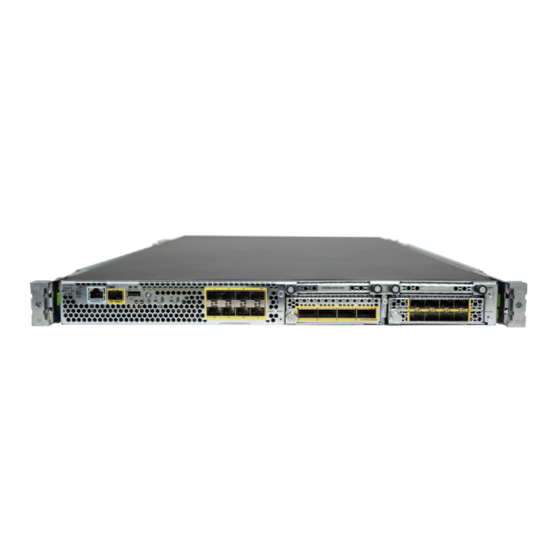
Power Cord Specifications, on page 32 Features The Cisco Firepower 4100 is a standalone modular security services platform. It is capable of running multiple security services simultaneously and so is targeted at the data center as a multiservice platform. The series includes the Firepower 4112, 4115, 4125, and 4145. - Page 6 One USB 2.0 Type A Network ports Eight fixed 1-Gb and 10-Gb SFP+ ports (named Ethernet 1/1 through 1/8) Small form-factor Eight fixed 1-Gb and 10-Gb SFP+ ports pluggable (SFP) ports Cisco Firepower 4112, 4115, 4125, and 4145 Hardware Installation Guide...
- Page 7 Ships with one 1100-W AC power supply module modules Hot-swappable Hot-swappable DC power supply Two (1+1) power supply module slots (optional) 950-W DC power supply module Hot-swappable Redundant power Six fan module slots 5+1 redundancy Hot-swappable Cisco Firepower 4112, 4115, 4125, and 4145 Hardware Installation Guide...
- Page 8 Firepower 4112 has not yet completed the above certifications. Note See the "Security Certifications Compliance" chapter in the Cisco FXOS CLI Configuration Guide Cisco FXOS Firepower Chassis Manager Configuration Guide for the procedure to enable security modes. Cisco Firepower 4112, 4115, 4125, and 4145 Hardware Installation Guide...
-
Page 9: Deployment Options
Figure 2: Firepower 4100 Package Contents Firepower 4100 chassis Blue console cable PC terminal adapter (part number 72-3383-01) Cisco Firepower 4112, 4115, 4125, and 4145 Hardware Installation Guide... -
Page 10: Serial Number Location
Safety Information Guide, the Getting Started Guide, and the Easy Deployment Guide. Serial Number Location The serial number for the Firepower 4100 series chassis is located on the pullout asset card on the front panel. Cisco Firepower 4112, 4115, 4125, and 4145 Hardware Installation Guide... - Page 11 Figure 3: Serial Number on the 4100 Chassis You can also view additional model information on the compliance label located on the bottom of the chassis. Figure 4: Compliance Label on the 4100 Chassis Cisco Firepower 4112, 4115, 4125, and 4145 Hardware Installation Guide...
-
Page 12: Front Panel
You can use the external USB Type A port to attach a data storage device. The external USB drive identifier is . The USB Type A port supports the following: disk1: Cisco Firepower 4112, 4115, 4125, and 4145 Hardware Installation Guide... -
Page 13: Front Panel Leds
• Security module log files • Platform bundle image upload using download image usbA: The USB Type A port does not support Cisco Secure Package (CSP) image upload. Network Ports The Firepower 4100 chassis has eight fixed ports that require 1-Gb/10-Gb SFP/SFP+ transceivers (fiber or copper). -
Page 14: Rear Panel
• Off—No connection or port is not in use. • Amber—No link or network failure. • Green—Link up. • Green, flashing—Network activity. Rear Panel The following figure shows the rear panel of the Firepower 4100. Cisco Firepower 4112, 4115, 4125, and 4145 Hardware Installation Guide... -
Page 15: Network Modules
Network modules are optional, removable I/O modules that provide either additional ports or different interface types (1/10/40 Gb). The Firepower network modules plug into the chassis on the front panel. Cisco Firepower 4112, 4115, 4125, and 4145 Hardware Installation Guide... -
Page 16: 10-Gb Network Module
You can fit four copper SFPs in either the top row of ports or the bottom row of ports. Both rows cannot be populated at the same time, because of the port row spacing. Figure 8: FPR4K-NM-8X10G Cisco Firepower 4112, 4115, 4125, and 4145 Hardware Installation Guide... -
Page 17: 40-Gb Network Module
For instructions on how to verify your firmware package version and to upgrade the firmware if necessary, see the Cisco Firepower 4100/9300 FXOS Firmware Upgrade Guide. See Cisco Firepower 4100/9300 FXOS Compatibility for the software compatibility matrix. Note The FPR4K-NM-4X40G is NEBS-compliant. Cisco Firepower 4112, 4115, 4125, and 4145 Hardware Installation Guide... -
Page 18: 100-Gb Network Module
For instructions on how to verify your firmware package version and to upgrade the firmware if necessary, see the Cisco Firepower 4100/9300 FXOS Firmware Upgrade Guide. See Cisco Firepower 4100/9300 FXOS Compatibility for the software compatibility matrix. Cisco Firepower 4112, 4115, 4125, and 4145 Hardware Installation Guide... -
Page 19: Hardware Bypass Network Modules
Hardware bypass is supported only on a fixed set of ports. You can pair Port 1 with Port 2, Port 3 with Port 4, but you cannot pair Port 1 with Port 4 for example. Cisco Firepower 4112, 4115, 4125, and 4145 Hardware Installation Guide... -
Page 20: 1-Gb Network Module With Hardware Bypass
The following figure shows the front panel view of the 1-Gb network module with hardware bypass (FPR-NM-8X1G-F). Pair ports 1 and 2, 3 and 4, 5 and 6, and 7 and 8 to form hardware bypass paired sets. Cisco Firepower 4112, 4115, 4125, and 4145 Hardware Installation Guide... - Page 21 LED B4 applies to this paired port. paired port. Network activity LEDs — • Left LED—Green indicates network activity when a 10M/100M/1G connection is made. • Right LED—Not in use at this time. Cisco Firepower 4112, 4115, 4125, and 4145 Hardware Installation Guide...
-
Page 22: 40-Gb Network Module With Hardware Bypass
• Amber—No connection, or port is not in use, or no link or network failure. • Amber, flashing—Port is in hardware bypass mode, failure event. • Green—Link up, no network activity. • Green, flashing—Network activity. Cisco Firepower 4112, 4115, 4125, and 4145 Hardware Installation Guide... -
Page 23: 1-Gb Sx/10-Gb Sr/10-Gb Lr Network Module With Hardware Bypass
For instructions on how to verify your firmware package version and to upgrade the firmware if necessary, see the Cisco Firepower 4100/9300 FXOS Firmware Upgrade Guide. See Cisco Firepower 4100/9300 FXOS Compatibility for the software compatibility matrix. Cisco Firepower 4112, 4115, 4125, and 4145 Hardware Installation Guide... - Page 24 Table 4: 1-Gb SX Network Module (FPR4K-NM-6X1SX-F) Operating Mode Typical Maximum Insertion loss Normal 0.9 dB 1.4 dB Hardware bypass 1.2 dB 1.7 dB Cisco Firepower 4112, 4115, 4125, and 4145 Hardware Installation Guide...
- Page 25 150 m 4700 (OM4) 200 m Table 6: 10-Gb LR Network Module (FPR4K-NM-6X10LR-F) Operating Mode Typical Maximum Insertion loss Normal 1.2 dB 1.6 dB Hardware bypass 1.5 dB 1.9 dB Cisco Firepower 4112, 4115, 4125, and 4145 Hardware Installation Guide...
-
Page 26: Power Supply Modules
The power supply modules are hot-swappable. Table 7: AC Power Supply Module Hardware Specifications Description Specification Input voltage 100 to 240 V AC Cisco Firepower 4112, 4115, 4125, and 4145 Hardware Installation Guide... - Page 27 950 W Redundancy 1+1 redundant Efficiency at 50% load Power Supply Module LEDs The following figure shows the two-color power supply LEDs. The LEDs are located on the upper right side. Cisco Firepower 4112, 4115, 4125, and 4145 Hardware Installation Guide...
-
Page 28: Fan Modules
Remove and replace one fan module at a time. If you remove a fan or a fan fails, the other fans operate at full speed, which can be noisy. Cisco Firepower 4112, 4115, 4125, and 4145 Hardware Installation Guide... -
Page 29: Supported Sfp/Sfp+ And Qsfp Transceivers
Keep unused transceivers in the ESD packing that they were shipped in. The following figure shows a sample SFP transceiver. Cisco Firepower 4112, 4115, 4125, and 4145 Hardware Installation Guide... - Page 30 Invisible laser radiation is present. Do not expose to users of telescopic optics. This applies to Class 1/1M laser products. The following table lists the Cisco supported transceivers. Table 10: Supported Cisco SFP/SFP+ Transceivers Optics Type 1 Gb 1G-SX GLC-SX-MMD 1G-LH/LX GLC-LH-SMD 1G-EX GLC-EX-SMD Cisco Firepower 4112, 4115, 4125, and 4145 Hardware Installation Guide...
- Page 31 10G AOC, 1m SFP-10G-AOC1M 10G AOC, 2m SFP-10G-AOC2M 10G AOC, 3m SFP-10G-AOC3M 10G AOC, 5m SFP-10G-AOC5M 10G AOC, 7m SFP-10G-AOC7M 10G AOC, 10m SFP-10GAOC10M 40 Gb 40G-SR4 QSFP-40G-SR4 40G-SR4-S QSFP-40G-SR4-S Cisco Firepower 4112, 4115, 4125, and 4145 Hardware Installation Guide...
-
Page 32: Hardware Specifications
Operating: 32 to 104° F (0 to 40° C) at sea level 1° C reduction of maximum for every 1000 ft (305 m) above sea level Nonoperating: -40 to 149°F (-40 to 65° C) Cisco Firepower 4112, 4115, 4125, and 4145 Hardware Installation Guide... -
Page 33: Product Id Numbers
Reference, in the Cisco Firepower Threat Defense Command Reference, or in the Cisco ASA Series Command Reference the procedure to display a list of the PIDs for your Firepower 4100. Cisco Firepower 4112, 4115, 4125, and 4145 Hardware Installation Guide... - Page 34 Firepower hardware accessory kit containing rack mounts and cables (spare) FPR4K-S-FAN FPR4K-S-FAN= Fan (spare) FPR4K-NM-2X40G-F 2-port 40-Gb SR hardware bypass network module FPR4K-NM-2X40G-F= 2-port 40-Gb SR hardware bypass network module (spare) Cisco Firepower 4112, 4115, 4125, and 4145 Hardware Installation Guide...
- Page 35 1100-W AC power supply module (spare) FPR4K-PWR-DC-950 950-W DC power supply module FPR4K-PWR-DC-950= 950-W DC power supply module (spare) FPR4K-RACK-MNT Rack-mount kit FPR4K-RACK-MNT= Rack-mount kit (spare) FPR4K-CBL-MGMT Cable management brackets Cisco Firepower 4112, 4115, 4125, and 4145 Hardware Installation Guide...
-
Page 36: Power Cord Specifications
Only the approved power cords or jumper power cords provided with the security appliance are supported. The following power cords are supported. Figure 17: Argentina CAB-9K10A-AR Plug: IRAM 2073 Cord set rating: 10 A, 250 V Connector: IEC 60320-C15 — Cisco Firepower 4112, 4115, 4125, and 4145 Hardware Installation Guide... - Page 37 Cord set rating: 10 A, 250 V Connector: EL 701B (EN 60320/C13) — Figure 20: Brazil PWR-CORD-G2A-BZ Plug: NBR 14136 Cord set rating: 10 A, 250 V Connector: IEC 60320-C13 — Cisco Firepower 4112, 4115, 4125, and 4145 Hardware Installation Guide...
- Page 38 Plug: DK3 Cord set rating: 10 A, 250 V Connector: IEC 60320-C13 — Figure 23: Europe CAB-AC-EUR Plug: CEE 7/7 Cord set rating: 10 A, 250 V Connector: IEC 60320-C15 — Cisco Firepower 4112, 4115, 4125, and 4145 Hardware Installation Guide...
- Page 39 Plug: SI-32 Cord set rating: 10 A, 250 V Connector: IEC 60320-C13 — Figure 26: Italy CAB-9K10A-IT Plug: CEI 23-16/VII Cord set rating: 10 A, 250 V Connector: IEC 60320-C15 — Cisco Firepower 4112, 4115, 4125, and 4145 Hardware Installation Guide...
- Page 40 Plug: NEMA L6-20P Cord set rating: 15 A, 250 V Connector: IEC 60320-C13 — Figure 29: Japan CAB-TA-JP Plug: NEMA5-15P/JIS 8303 Cord set rating: 12 A, 125 V Connector: IEC 60320-C15 — Cisco Firepower 4112, 4115, 4125, and 4145 Hardware Installation Guide...
- Page 41 Cord set rating: 10 A, 250 V Connector: IEC 60320-C13 — Figure 32: South Africa CAB-9K10A-SA Plug: SABS 164 Cord set rating: 10 A, 250 V Connector: IEC 60320-C15 — Cisco Firepower 4112, 4115, 4125, and 4145 Hardware Installation Guide...
- Page 42 Plug: CNS10917-2 Cord set rating: 10 A, 125 V Connector: IEC 60320-C15 — Figure 35: United Kingdom CP-PWR-CORD-UK Plug: BS1363A/SS145 Cord set rating: 10 A, 250 V Connector: IEC 60320-C13 — Cisco Firepower 4112, 4115, 4125, and 4145 Hardware Installation Guide...
-
Page 43: Installation Warnings
Use the statement number provided at the end of each warning statement to locate its translation in the translated safety warnings for this device. SAVE THESE INSTRUCTIONS Cisco Firepower 4112, 4115, 4125, and 4145 Hardware Installation Guide... - Page 44 Do not operate the system unless all cards, faceplates, front covers, and rear covers are in place. Warning Statement 1030 Equipment Installation Only trained and qualified personnel should be allowed to install, replace, or service this equipment. Cisco Firepower 4112, 4115, 4125, and 4145 Hardware Installation Guide...
- Page 45 See statement 1089 for the definition of an instructed or skilled person. Warning Statement 9001 Product Disposal Ultimate disposal of this product should be handled according to all national laws and regulations. Cisco Firepower 4112, 4115, 4125, and 4145 Hardware Installation Guide...
-
Page 46: Network Equipment-Building System (Nebs) Statements
To comply with the emission and immunity requirements of GR-1089, shielded cables are required for the following ports: Gigabit Ethernet management port RJ-45 1 G/100 M/10 M auto duplex/auto MDI-X Base-T ports Cisco Firepower 4112, 4115, 4125, and 4145 Hardware Installation Guide... - Page 47 This equipment is suitable for installation in network telecommunications facilities. Note Statement 8016 Installation Location Where the National Electric Code (NEC) Applies This equipment is suitable for installation in locations where the NEC applies. Cisco Firepower 4112, 4115, 4125, and 4145 Hardware Installation Guide...
-
Page 48: Safety Recommendations
Always follow ESD-prevention procedures when removing and replacing components. Ensure that the chassis is electrically connected to an earth ground. Wear an ESD-preventive wrist strap, ensuring that it makes good Cisco Firepower 4112, 4115, 4125, and 4145 Hardware Installation Guide... -
Page 49: Site Environment
• The chassis does not have a user-selectable operating range. Refer to the label on the chassis for the correct appliance input-power requirement. • Several styles of AC-input power supply cords are available for the chassis; make sure that you have the correct style for your site. Cisco Firepower 4112, 4115, 4125, and 4145 Hardware Installation Guide... -
Page 50: Rack Configuration Considerations
• Baffles can help to isolate exhaust air from intake air, which also helps to draw cooling air through the chassis. The best placement of the baffles depends on the airflow patterns in the rack. Experiment with different arrangements to position the baffles effectively. Cisco Firepower 4112, 4115, 4125, and 4145 Hardware Installation Guide... -
Page 51: Rack-Mount And Ground The Chassis
• Effect of damage on the installation Rack-Mount the Chassis This procedure describes how to install the Firepower 4100 in a rack using the rack kit that shipped with the chassis. Cisco Firepower 4112, 4115, 4125, and 4145 Hardware Installation Guide... - Page 52 To prevent personal injury or damage to the chassis, never attempt to lift or tilt the chassis using the handles on modules, such as power supplies, fans, or cards. These types of handles are not designed to support the weight of the unit. Cisco Firepower 4112, 4115, 4125, and 4145 Hardware Installation Guide...
- Page 53 Secure the inner rail to the side of the chassis using one M3 x 6 mm screw. e) Install the second inner rail to the opposite side of the chassis and secure with the other M3 x 6 mm screw. Cisco Firepower 4112, 4115, 4125, and 4145 Hardware Installation Guide...
- Page 54 On the outside of the assembly, push the green arrow button toward the rear to open the securing plate. Figure 38: Front Securing Mechanism Inside the Front End Cisco Firepower 4112, 4115, 4125, and 4145 Hardware Installation Guide...
- Page 55 Slide the release clip toward the rear on both inner rails, and then continue pushing the chassis into the rack until the mounting brackets meet the front of the slide rail. Cisco Firepower 4112, 4115, 4125, and 4145 Hardware Installation Guide...
-
Page 56: Ground The Chassis
M4 holes is provided on the chassis for attaching a grounding lug. The grounding lug must be Nationally Recognized Testing Laboratory (NRTL)-listed. In addition, a copper conductor (wires) must be used and the copper conductor must comply with National Electrical Code (NEC) code for ampacity. Cisco Firepower 4112, 4115, 4125, and 4145 Hardware Installation Guide... - Page 57 Use a wire-stripping tool to remove approximately 0.75 inches (19 mm) of the covering from the end of the grounding cable. Step 2 Insert the stripped end of the grounding cable into the open end of the grounding lug. Figure 40: Insert the Cable into the Grounding Lug Cisco Firepower 4112, 4115, 4125, and 4145 Hardware Installation Guide...
- Page 58 Install the FIPS Opacity Shield, on page 76 for the procedure. Install the cables according to your default software configuration as described in the Cisco Firepower 4100 Getting Started Guide. Cisco Firepower 4112, 4115, 4125, and 4145 Hardware Installation Guide...
-
Page 59: Installation, Maintenance, And Upgrade
Acknowledgment is necessary if you decommission and physically remove a network module and do not replace it, or if you replace it with another PID. See the "Acknowledge a Network Module” topic in Cisco Firepower 4112, 4115, 4125, and 4145 Hardware Installation Guide... - Page 60 Statement 1091 Installation by an Instructed Person Only an instructed person or skilled person should be allowed to install, replace, or service this equipment. See statement 1089 for the definition of an instructed or skilled person. Cisco Firepower 4112, 4115, 4125, and 4145 Hardware Installation Guide...
- Page 61 To remove a network module from the chassis, loosen the captive screw on the lower left side of the network module and pull out the handle that is connected to the screw. This mechanically ejects the network module from the slot. Figure 41: Remove the Network Module Cisco Firepower 4112, 4115, 4125, and 4145 Hardware Installation Guide...
-
Page 62: Remove And Replace The Fan Module
Once you have aligned the fan with the fan slot, insert the new fan within five seconds. Do not partially engage the fan module and let the fan spin in the wrong direction before fully seating it. Safety Warnings Take note of the following component replacement safety warnings: Cisco Firepower 4112, 4115, 4125, and 4145 Hardware Installation Guide... - Page 63 To remove a fan module, face the rear of the chassis, and grasp the handle of the fan module. Step 2 Squeeze the handle to disengage the latches on the left and right of the fan module. Step 3 Pull the fan module out of the chassis. Cisco Firepower 4112, 4115, 4125, and 4145 Hardware Installation Guide...
-
Page 64: Remove And Replace The Ssd
You storage SSD must be installed in slot 1 and must be present. Slot 1 is reserved for the logical device application instance (threat defense or ASA). Only an optional MSP can be installed in the second SSD slot Cisco Firepower 4112, 4115, 4125, and 4145 Hardware Installation Guide... - Page 65 Statement 1090 Installation by Skilled Person Only a skilled person should be allowed to install, replace, or service this equipment. See statement 1089 for the definition of a skilled person. Cisco Firepower 4112, 4115, 4125, and 4145 Hardware Installation Guide...
- Page 66 Tighten the captive screws on either side of the SSD. Step 8 Verify that the SSD is operational by checking the SSD LED. See Front Panel LEDs, on page 9 for a description of the fan LEDs. Cisco Firepower 4112, 4115, 4125, and 4145 Hardware Installation Guide...
-
Page 67: Remove And Replace The Power Supply Module
To reduce risk of electric shock and fire, a readily accessible two-poled disconnect device must be incorporated in the fixed wiring. Warning Statement 1025 Use Copper Conductors Only To reduce risk of fire, use copper conductors only. Cisco Firepower 4112, 4115, 4125, and 4145 Hardware Installation Guide... - Page 68 A skilled person or qualified personnel is someone who has training or experience in the equipment technology and understands potential hazards when working with equipment. Cisco Firepower 4112, 4115, 4125, and 4145 Hardware Installation Guide...
- Page 69 Press the latch found on the lower right of the power supply to disengage the power supply. Step 3 Place your other hand under the power supply module to support it while you slide it out of the chassis. Cisco Firepower 4112, 4115, 4125, and 4145 Hardware Installation Guide...
- Page 70 Push in the power supply module gently until you hear the latch engage and it is seated. Verify the power supply module is operating correctly by checking the power supply module LED. See Power Supply Modules, on page 22 for a description of the power supply module LEDs. Cisco Firepower 4112, 4115, 4125, and 4145 Hardware Installation Guide...
-
Page 71: Connect The Dc Power Supply Module
To avoid hazardous conditions, all components in the area where DC input power is accessible must be properly insulated. Therefore, before installing the DC cable lugs, be sure to insulate the lugs according to the manufacturer's instructions Cisco Firepower 4112, 4115, 4125, and 4145 Hardware Installation Guide... - Page 72 To reduce risk of electric shock and fire, a readily accessible two-poled disconnect device must be incorporated in the fixed wiring. Warning Statement 1025 Use Copper Conductors Only To reduce risk of fire, use copper conductors only. Cisco Firepower 4112, 4115, 4125, and 4145 Hardware Installation Guide...
- Page 73 A skilled person or qualified personnel is someone who has training or experience in the equipment technology and understands potential hazards when working with equipment. Cisco Firepower 4112, 4115, 4125, and 4145 Hardware Installation Guide...
- Page 74 Insulate the lug with shrink sleeving for each lead wire if using noninsulated crimp terminals. Sleeving is not required for insulated terminals. Step 6 Remove the two M5 screws. Cisco Firepower 4112, 4115, 4125, and 4145 Hardware Installation Guide...
- Page 75 Tighten the M5 screw with the captive washer to the recommended torque of 5 in-lbs for the positive stud and wire. Secure the wires coming in from the terminal block so that they cannot be disturbed by casual contact. Cisco Firepower 4112, 4115, 4125, and 4145 Hardware Installation Guide...
- Page 76 Replace the terminal block plastic cover. The plastic cover is slotted and keyed to fit correctly over the terminal block. This cover should always be in place when power is applied to the terminals. Figure 50: Replace the Plastic Cover Cisco Firepower 4112, 4115, 4125, and 4145 Hardware Installation Guide...
-
Page 77: Secure The Power Cord On The Ac Power Supply Module
Only trained and qualified personnel should be allowed to install, replace, or service this equipment. Warning Statement 1073 No User-Serviceable Parts There are no serviceable parts inside. To avoid risk of electric shock, do not open. Cisco Firepower 4112, 4115, 4125, and 4145 Hardware Installation Guide... - Page 78 To remove the tie wrap from the clamp, push the lever on the closed side of the box-shaped channel and slide out the tie wrap. Figure 51: Tie Wrap Through the Box Channel of the Clamp Tie wrap Box channel Step 2 Attach the clamp to the power supply module: Cisco Firepower 4112, 4115, 4125, and 4145 Hardware Installation Guide...
- Page 79 Figure 52: Flextronics Power Supply Module Flextronics tie wrap Hexagonal hole Figure 53: Artesyn Power Supply Module Artesyn tie wrap Hexagonal hole Cisco Firepower 4112, 4115, 4125, and 4145 Hardware Installation Guide...
-
Page 80: Install The Fips Opacity Shield
Because the FIPS opacity shield covers the serial number on the chassis, you need to copy the serial number on a label and attach it to the chassis where it can be retrieved or viewed easily before you install the FIPS opacity shield. You need the serial number when you call Cisco TAC. Before you begin... - Page 81 You should have completed this step while preforming the procedure described in Rack-Mount the Chassis, Note on page Figure 55: Attach the Slide Rail Locking Bracket to the Side of the Chassis Cisco Firepower 4112, 4115, 4125, and 4145 Hardware Installation Guide...
- Page 82 Step 7 below. Step 6 Route the cables through the openings in the cable management brackets. Cisco Firepower 4112, 4115, 4125, and 4145 Hardware Installation Guide...
- Page 83 Figure 57: Route the Cables Through the Cable Management Brackets Step 7 Attach the FIPS opacity shield to the cable management brackets using the four 8-32 x 0.375-inch Phillips screws provided in the FIPS kit. Cisco Firepower 4112, 4115, 4125, and 4145 Hardware Installation Guide...
- Page 84 OFF or unplugging the power cord, wait at least 10 seconds before turning power back ON. Step 12 See the Cisco Firepower 4100 Getting Started Guide for further configuration information. Cisco Firepower 4112, 4115, 4125, and 4145 Hardware Installation Guide...
Need help?
Do you have a question about the 4112 and is the answer not in the manual?
Questions and answers