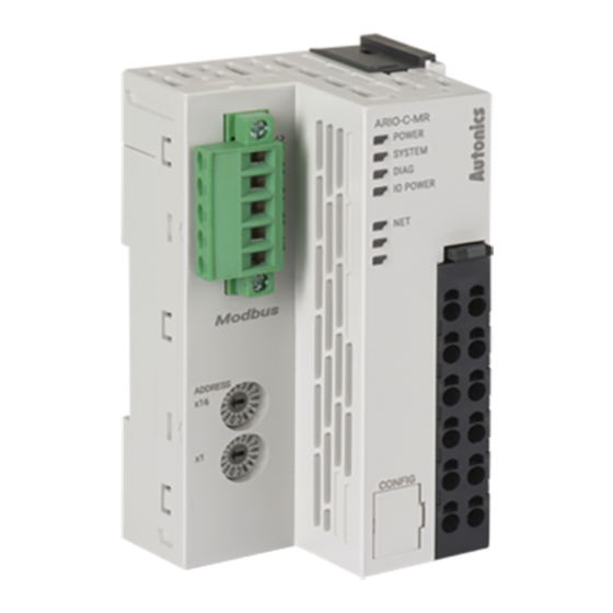
Autonics ARIO-C-MR Manual
Modbus rtu-based coupler
Hide thumbs
Also See for ARIO-C-MR:
- Product manual (4 pages) ,
- User manual (60 pages) ,
- Product manual (12 pages)
Table of Contents
Advertisement
Quick Links
Advertisement
Table of Contents

Related Manuals for Autonics ARIO-C-MR


Summary of Contents for Autonics ARIO-C-MR
- Page 1 Field Network Devices ARIO-C-MR (ModbusRTU compatible) Thank you for purchasing an Autonics product. This user manual contains information about the product and its proper use, and should be kept in a place where it will be easy to access. www.autonics.com...
- Page 2 © Copyright Reserved Autonics Co., Ltd.
-
Page 3: Preface
Preface Preface Thank you for purchasing Autonics product. Please familiarize yourself with the information contained in the Safety Considerations section before using this product. This user manual contains information about the porduct and its proper use, and should be kept in a place where it will be easy to access. -
Page 4: Coupler Manual Guide
Please visit our website (www.autonics.com) to download a copy. The manual's content may vary depending on changes to the product's software and other unforeseen developments within Autonics, and is subject to change without prior notice. Upgrade notice is provided through our homepage. ... -
Page 5: Coupler Manual Symbols
Failure to follow instructions can result in serious injury or death. Failure to follow instructions can lead to a minor injury or product damage. An example of the concerned feature’s use. ※1 Annotation mark. © Copyright Reserved Autonics Co., Ltd. -
Page 6: Safety Considerations
Do not cut off power or disconnect connectors (or terminals) while operating the unit. Failure to follow this instruction may result in fire or product damage. ※ The specifications and dimensions of this manual are subject to change without any notice © Copyright Reserved Autonics Co., Ltd. -
Page 7: Caution During Use
For removing the terminal, body or base, do not operate units for a long time without it. This unit may be used in the following environments. ① Indoors ② Altitude max. 2,000m ③ Pollution degree 2 ④ Installation category II © Copyright Reserved Autonics Co., Ltd. -
Page 8: Table Of Contents
Memory area ...................... 23 Gather diagnostic information of modules ............23 Process image ....................24 Example of memory map ................... 24 5.6.1 Device......................24 5.6.2 Input process image ................... 24 5.6.3 Output process image ................25 viii © Copyright Reserved Autonics Co., Ltd. -
Page 9: Table Of Contents
Table of Contents 5.6.4 Memory map based on field network ............25 Diagnosis function ..................26 Overview ......................26 Diagnostic type ....................26 Definition ......................27 © Copyright Reserved Autonics Co., Ltd. -
Page 10: Reference Manuals
DAQMaster, a device integration management program, provides the expanded user convenience. You can use the module setting, real-time control, and monitoring/diagnosis function of input/output signal (except ARIO-C-PN and ARIO-C-PB). Also, you can arrange products through virtual mode and recommended sorting. © Copyright Reserved Autonics Co., Ltd. -
Page 11: Protocol Overview
(PLCs). Simple and robust, Modbus RTU is the de facto standard communication protocol and a means for connecting industrial electronics. ARIO-C-MR, Modbus RTU-based coupler, synchronizes the data of all connected I / O modules with Modbus RTU. The coupler determines the physical structure of the node and automatically creates a local process image of all the I / O. -
Page 12: Input Register
Description Value Function Register 1030 Baudrate - 0: 2.4 kbps - 1: 4.8 kbps - 2: 9.6 kbps - 3: 19.2 kbps - 4: 38.4 kbps - 5: 57.6 kbps - 6: 115.2 kbps © Copyright Reserved Autonics Co., Ltd. -
Page 13: Holding Register
- 3: 19.2 kbps - 4: 38.4 kbps - 5: 57.6 kbps - 6: 115.2 kbps 03/06/16 1031 Parity bit - 0: None - 1: Even - 2: Odd 03/06/16 1032 Stop bit (1, 2) © Copyright Reserved Autonics Co., Ltd. -
Page 14: Specifications
Rotary switch for communication setting in ARIO (Station no.) Topology Bus, Trunk, Drop Line, Daisy Chain Installation method DIN rail mounting PC connection with USB 2.0 Micro type connector Setting and monitoring (comprehensive device management program, DAQMaster) © Copyright Reserved Autonics Co., Ltd. - Page 15 ※2. If it over the limit size or connected units, system may be error. ※3. Autonics test standard ※4. The weight includes packaging. The weight in parenthesis is for unit only. ※ Environment resistance is rated at no freezing or condensation. © Copyright Reserved Autonics Co., Ltd.
-
Page 16: Hardware
4 Hardware Hardware Dimensions (1) Coupler (2) End module © Copyright Reserved Autonics Co., Ltd. -
Page 17: Unit Descriptions
6. ABUS comm. connector: Input terminal that supplies circuit driving power of the coupler, ABUS, and modul by receiving 24VDC. I/O power supply : Supplies power for input / output signal of module by receiving DC, AC, etc. © Copyright Reserved Autonics Co., Ltd. -
Page 18: Rotary Switch For Communication Setting
The rotary switch cannot be changed while the power is operating. To apply the changed rotary switch, the coupler must be turned on again. However, it is available up to 32 nodes in a single segment. © Copyright Reserved Autonics Co., Ltd. -
Page 19: Status Indicator
There is no maximum ㅡ removed module, module is connected module / is inserted. operating module.(re data size covery (normal operation) (recovery exceeded failed) failed) ㅡ ㅡ ㅡ ㅡ ㅡ Green POWER © Copyright Reserved Autonics Co., Ltd. - Page 20 State on offline or no network power MAC address test incomplete Data exchange timeout Flashing Communication connection timeout (slave is not connected, no network power) Serious errors in the network such as connection, network, and duplicate MAC address © Copyright Reserved Autonics Co., Ltd.
-
Page 21: Memory Map
If the I / O form is smaller than the data handling method, the space is filled with zeros (pending) and managed. Ex) ARIO-S-DI04P has 4 bits of data. In this case, □□□□ B B B B but, ARIO series transfers 0000BBBB by replacing □ area with number 0. © Copyright Reserved Autonics Co., Ltd. -
Page 22: Memory Structure
In addition, the coupler provides input and output information of the unit in accordance with the data size set in the field network. When the diagnosis function is activated, the coupler provides data embed with additional input area. © Copyright Reserved Autonics Co., Ltd. -
Page 23: Memory Area
The coupler transmits the diagnostic information of itself and modules to the master of field network according to the settings, which is cyclically updated. This information allows you to remotely check the status of each coupler. © Copyright Reserved Autonics Co., Ltd. -
Page 24: Process Image
Analog input module 2, channel 2, High byte Analog input module 2, channel 2, Low byte DI2P4 DI2P3 DI2P2 DI2P1 DI3P4 DI3P3 DI3P2 DI3P1 DI1P1 stands for 1st Point of Digital Input Module 1. © Copyright Reserved Autonics Co., Ltd. -
Page 25: Output Process Image
402001 06 / 16 2001 AO1CH1H AO1CH1L only write 402002 06 / 16 2002 AO1CH1H AO1CH1L only write 402003 06 / 16 2003 only write 402004 06 / 16 2004 only write © Copyright Reserved Autonics Co., Ltd. -
Page 26: Diagnosis Function
Save to the memory map via the cyclic internal bus communication of the Message transfer product method In case of the interrupt setting, immediate bus communication starts when an error occurs Display on the product (coupler) and module according to the diagnostic information © Copyright Reserved Autonics Co., Ltd. -
Page 27: Definition
All module is not connected, the number of modules is out of the range, module size is out of range, module is not recognized via ABUS ABUS due to the abnormal coupler configuration. Constructor 0: Module configuration completed (configuration state of ABUS) 1: Incomplete module configuration © Copyright Reserved Autonics Co., Ltd. - Page 28 * Dimensions or specifications on this manual are subject to change and some models may be discontinued without notice. MOO-ARIOCMRU-V1.1-1905US...
Need help?
Do you have a question about the ARIO-C-MR and is the answer not in the manual?
Questions and answers