Table of Contents
Advertisement
Quick Links
Introduction
The
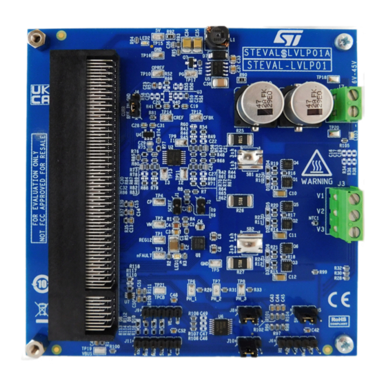
STEVAL-LVLP01
evaluation board is based on the STDRIVE101 three-phase gate driver and the STL8N10F7 power
MOSFETs.
The
STEVAL-LVLP01
embeds a power stage and circuitry for driving three-phase brushless DC motors. The board can be
interfaced with different control boards based on STM32 microcontrollers through the MC Connector V2, which is a part of motor
control development platform supporting ZeST and HSO Algorithms.
The
STEVAL-LVLP01
can support single-shunt or three-shunt operation. The different connectors for onboard motor positioning
feedback and motor phase sensing network allow implementation of sensor and sensorless algorithms for motion control.
UM3193 - Rev 1 - October 2023
For further information contact your local STMicroelectronics sales office.
Getting started with the STEVAL-LVLP01 evaluation board
Figure 1.
STEVAL-LVLP01 evaluation board
UM3193
User manual
www.st.com
Advertisement
Table of Contents

Related Manuals for ST STEVAL-LVLP01


Summary of Contents for ST STEVAL-LVLP01
-
Page 1: Figure 1. Steval-Lvlp01 Evaluation Board
UM3193 User manual Getting started with the STEVAL-LVLP01 evaluation board Introduction STEVAL-LVLP01 evaluation board is based on the STDRIVE101 three-phase gate driver and the STL8N10F7 power MOSFETs. STEVAL-LVLP01 embeds a power stage and circuitry for driving three-phase brushless DC motors. The board can be interfaced with different control boards based on STM32 microcontrollers through the MC Connector V2, which is a part of motor control development platform supporting ZeST and HSO Algorithms. -
Page 2: Hardware Description And Configuration
UM3193 Hardware description and configuration Hardware description and configuration The main components and connectors of the STEVAL-LVLP01 are shown in the figure and tables below. Figure 2. STEVAL-LVLP01 main components and connectors Table 1. STEVAL-LVLP01 configuration jumpers Ref. Label Description Default Allows to short the SCREF pin of the STDRIVE101 to 3.3V, thus disabling... -
Page 3: Table 2. Steval-Lvlp01 Connectors
VSPI SPI interface supply voltage (selectable by J10). GND reference for the SPI interface. Table 3. STEVAL-LVLP01 test points Ref. Label Description Test point connected to the REG12 pin of the STDRIVE101; it is the output of the embedded linear regulator REG12 and the supply of the gate drivers. -
Page 4: Mc Connector V2
• The category of the pin according to the functional block associated • The direction of the signal, whether from the power board STEVAL-LVLP01 to the control board (P → C) or vice-versa (P → C) • The description of the signal function... -
Page 5: Table 4. Pin Mapping Of The Mc Connector V2
SPI peripheral (Master) on the control board. P → C SPI_MISO MISO signal generated by the slave device connected to J11 on the STEVAL-LVLP01. C → P SPI_SCK Serial clock signal generated by the SPI peripheral (Master) on the control board. - Page 6 UM3193 MC connector V2 Pin No. Category Direction Signal Name Description Current sensing signal (negative) related to motor’s phase 3 (W) (see Operational Motor Feedback P → C ISNS3N amplifiers). Power Reference GND P → C VSNS1 Voltage of the motor’s phase 1 (U) rescaled and filtered. Reference GND P →...
-
Page 7: Getting Started
Getting started Getting started Table 5 summarizes the maximum ratings of the STEVAL-LVLP01. To run the motor follows the points below: Step 1. Plug a compatible control board in the MC Connector V2 (J12), programmed with the target firmware Step 2. -
Page 8: Hardware And Functional Blocks Description
Hardware and functional blocks description The STEVAL-LVLP01 is based on the STDRIVE101 three-phase gate driver. The power stage is based on six N- channel STL8N10F7 power MOSFETs in the 3.3 x 3.3 powerFLAT package. The digital control signals and the feedback signals are routed on the MC connector V2, which acts as interface for the control board. -
Page 9: Figure 5. Solder Bridges Configuration For Three-Shunt Operation
UM3193 Current sensing Figure 5. Solder bridges configuration for three-shunt operation Figure 6. Solder bridges configuration for single shunt operation In case of single shunt operation (Figure 6) the solder bridges redirect the current of the three phases to flow in the shunt resistor of the phase 2 (R26);... -
Page 10: Operational Amplifiers
However, it is possible to change this configuration and use the operational amplifiers present on the STEVAL-LVLP01. The signal of each shunt resistor has a dedicated op-amp, which implements a differential amplifier with a gain of 15. The topology used enables the rejection of the common mode, resulting in a more accurate output signal. -
Page 11: Comparator For Current Control
UM3193 Motor phase voltage 2.2.3 Comparator for current control The current control feature is implemented using the ETR pin of the microcontroller: this pin acts directly on the timer driving the gate drivers of the STDRIVE101. The ETR signal is triggered when the value of the current reaches the selected threshold. -
Page 12: Board Id
Board ID The board ID provides a voltage level which identifies the STEVAL-LVLP01; this analog voltage is obtained with a resistor divider referred to the VDD, which is 3.3 V typical and it is also the supply of the microcontroller on the control board. -
Page 13: Hall Sensor Connector
UM3193 Bus voltage monitoring Figure 11. Strip connectors for motor sensor feedback 2.5.1 Hall sensor connector The Hall sensor connector J6 supports digital Hall sensors with open drain output. The 4.7 kΩ pull-up resistors (R96, R97, R98) connected to VDD shift the input signals to a level compatible with the microcontroller’s inputs range. -
Page 14: Stdrive101 Feature Descriptions
UM3193 STDRIVE101 feature descriptions STDRIVE101 feature descriptions Overcurrent comparator The STDRIVE101 integrates a comparator, which disables the power stage whenever the voltage on its input (CP pin) exceed the internal threshold VREF,DRV (about 0.5V). The values of the currents in each phase are acquired and combined through a resistors’... -
Page 15: Fault Monitoring
UM3193 Fault monitoring Direct Mode EN/IN Mode STDRIVE101 Pin name (number) (R5 = 0 Ω) (50kΩ < R5 < 250 kΩ) INL2 (digital control input for the LS driver on EN2 (digital control of the half bridge 2: enable/high INL2/EN2 (11) half bridge 2) impedance) INL3 (digital control input for the LS driver on... -
Page 16: Schematic Diagrams
Schematic diagrams Figure 12. STEVAL-LVLP01 circuit schematic (1 of 6) Gate Driver STDRIVE101 STDRIVE101 VDS monitoring threshold REG12 SCREF TP 1 TP 2 S CREF 22uF 220nF 100nF 100V 100V TP 3 10nF LED1 S CREF nFAULT MODE/DT nFAULT Open (default): Vds monitoring protection enabled... -
Page 17: Figure 13. Steval-Lvlp01 Circuit Schematic (2 Of 6)
Figure 13. STEVAL-LVLP01 circuit schematic (2 of 6) 6 7 8 6 7 8 6 7 8 R10 100 R11 100 R12 100 220nF 220nF 220nF GHS 1 GHS 2 GHS 3 100V 100V 100V R13 39 R14 39 R15 39... -
Page 18: Figure 14. Steval-Lvlp01 Circuit Schematic (3 Of 6)
Figure 14. STEVAL-LVLP01 circuit schematic (3 of 6) Phase Current sensing Voltage reference generation OP REF VDD_f VDD_c TP 9 R43 0 100nF 100nF S HUNT1P R44 1k 0.1% 0.1% S HUNT1P OUT 7 R46 NM IS NS 1P S HUNT1N... -
Page 19: Figure 15. Steval-Lvlp01 Circuit Schematic (4 Of 6)
Figure 15. STEVAL-LVLP01 circuit schematic (4 of 6) Buck converter for 5V generation 100nF Buck_OUT 100V Buck_OUT TP 15 TP 16 S T1S 14P HR L1 10uH GND_S BOOT TP 17 P _GOOD S TP S 2L60 4.7k 100nF 4.7uF... -
Page 20: Figure 16. Steval-Lvlp01 Circuit Schematic (5 Of 6)
Figure 16. STEVAL-LVLP01 circuit schematic (5 of 6) Hall sensors connector Power supply connector (VM) Hall sensors supply: default to 5V TP 18 R100 TP 19 VBUS 4.7k 4.7k 4.7k VBUS R101 3.3k LED3 R102 3.3k R103 GREEN 47uF 47uF R104 3.3k... -
Page 21: Figure 17. Steval-Lvlp01 Circuit Schematic (6 Of 6)
Figure 17. STEVAL-LVLP01 circuit schematic (6 of 6) MC connector V2 J 12-1 J 12-2 SPI1_nSS SPI1_MISO S P I_nS S S P I_MIS O SPI1_SCK SPI1_MOSI S P I_S CK S P I_MOS I 5V to Control Board 5V to Control Board 3.3V from Control Board... -
Page 22: Bill Of Materials
UM3193 Bill of materials Bill of materials Table 8. STEVAL-LVLP01 bill of materials Item Q.ty Ref. Part/value Description Manufacturer Order code SMT ceramic 22uF Taiyo Yuden TMK325B7226KM-PR capacitor (X7R) SMT ceramic 220nF Murata GCM188R71E224KA55D capacitor (X7R) C3, C33, SMT ceramic... - Page 23 UM3193 Bill of materials Item Q.ty Ref. Part/value Description Manufacturer Order code D1, D2, D3, D4, Small signal Schottky D5, D6, BAT30K, SOD-523 STMicroelectronics BAT30KFILM diodes D8, D9, Low drop power STPS2L60, SMA STMicroelectronics STPS2L60A Schottky rectifier JP1, JP2 GND_node PCB shape N.A.
- Page 24 UM3193 Bill of materials Item Q.ty Ref. Part/value Description Manufacturer Order code R5, R16, R17, R18, R43, R45, R51, R52, SMT resistor TE Connectivity CRG0603ZR R54, R62, R64, R71, R79, R82, R88, R118 5.1k SMT resistor Vishay CRCW06035K10FKEA R7, R8, 2.2k SMT resistor TE Connectivity...
- Page 25 UM3193 Bill of materials Item Q.ty Ref. Part/value Description Manufacturer Order code R90, R92 SMT resistor TE Connectivity CRG0805ZR SMT resistor Vishay CRCW060347K0FKEA 1.5k SMT resistor TE Connectivity CRG0603F1K5 R93, R96, 4.7k SMT resistor Bourns CR0603-FX-4701ELF R97, R98 R101, R102, 3.3k SMT resistor TE Connectivity...
- Page 26 UM3193 Bill of materials Item Q.ty Ref. Part/value Description Manufacturer Order code WA-SBRIE Brass Spacer Stud internal/ WURTH MECH3 spacer stud M/F 971050324 external M3 thread, ELEKTRONIK WA-SBRII Brass Spacer Stud internal/ WURTH MECH4 spacer stud F/F 970100354 external M3 thread, ELEKTRONIK 10mm UM3193 - Rev 1...
-
Page 27: Board Versions
UM3193 Board versions Board versions Table 9. STEVAL-LVLP01 versions Finished good Schematic diagrams Bill of materials STEVAL$LVLP01A STEVAL$LVLP01A schematic diagrams STEVAL$LVLP01A bill of materials 1. This code identifies the STEVAL-LVLP01 evaluation board first version. UM3193 - Rev 1 page 27/33... -
Page 28: Regulatory Compliance Information
UM3193 Regulatory compliance information Regulatory compliance information Notice for US Federal Communication Commission (FCC) For evaluation only; not FCC approved for resale FCC NOTICE - This kit is designed to allow: (1) Product developers to evaluate electronic components, circuitry, or software associated with the kit to determine whether to incorporate such items in a finished product and (2) Software developers to write software applications for use with the end product. -
Page 29: Revision History
UM3193 Revision history Table 10. Document revision history Date Version Changes 24-Oct-2023 Initial release. UM3193 - Rev 1 page 29/33... -
Page 30: Table Of Contents
UM3193 Contents Contents Hardware description and configuration ......... . . 2 MC connector V2. - Page 31 STEVAL-LVLP01 main components and connectors ........
- Page 32 STEVAL-LVLP01 configuration jumpers ........
- Page 33 ST’s terms and conditions of sale in place at the time of order acknowledgment. Purchasers are solely responsible for the choice, selection, and use of ST products and ST assumes no liability for application assistance or the design of purchasers’...
Need help?
Do you have a question about the STEVAL-LVLP01 and is the answer not in the manual?
Questions and answers