KROHNE OPTISWIRL 2100 Supplementary Instructions Manual
Vortex flowmeter
Hide thumbs
Also See for OPTISWIRL 2100:
- Supplementary instructions manual (28 pages) ,
- Handbook (100 pages)
Table of Contents
Advertisement
Quick Links
OPTISWIRL 2100
OPTISWIRL 2100
OPTISWIRL 2100
OPTISWIRL 2100
Vortex flowmeter
Equipment category II 2 G and II 2 D, EPL Gb and Db
in protection type "Flameproof enclosure" Ex d and
in protection type "Increased safety" Ex e and
in protection type "Equipment - dust ignition protection by enclosure" Ex t
© KROHNE 10/2020 - 4008164801 - AD OPTISWIRL2100 Exd R01 en
Supplementary Instructions
Supplementary Instructions
Supplementary Instructions
Supplementary Instructions
Advertisement
Table of Contents

Related Manuals for KROHNE OPTISWIRL 2100


Summary of Contents for KROHNE OPTISWIRL 2100
- Page 1 Equipment category II 2 G and II 2 D, EPL Gb and Db in protection type "Flameproof enclosure" Ex d and in protection type "Increased safety" Ex e and in protection type "Equipment - dust ignition protection by enclosure" Ex t © KROHNE 10/2020 - 4008164801 - AD OPTISWIRL2100 Exd R01 en...
-
Page 2: Table Of Contents
CONTENTS OPTISWIRL 2100 1 Safety instructions 1.1 General notes ........................3 1.2 EU conformity ........................3 1.3 Approval according to the IECEx scheme ................ 3 1.4 Safety instructions......................4 2 Device description 2.1 Device description ......................5 2.2 Description code....................... 5 2.3 Marking.......................... -
Page 3: Safety Instructions
SAFETY INSTRUCTIONS OPTISWIRL 2100 1.1 General notes This additional instruction applies to explosion-protected versions of vortex flowmeters with protection type flameproof enclosure "d", increased safety "e" and equipment dust-ignition protection through enclosure "t", equipment protection level EPL Gb and EPL Db. -
Page 4: Safety Instructions
SAFETY INSTRUCTIONS OPTISWIRL 2100 1.4 Safety instructions If these instructions are not followed, there is a risk of explosion. Assembly, installation, start-up and maintenance may only be performed by personnel trained in personnel trained in personnel trained in personnel trained in... -
Page 5: Device Description
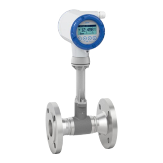
* positions which are not needed are omitted (no blank positions) The remote version consisting of the flow sensor OPTISWIRL 2000 F and the signal converter VFC 100 F 020 is called the OPTISWIRL 2100 F. 10/2020 - 4008164801 - AD OPTISWIRL2100 Exd R01 en... -
Page 6: Marking
On the remote versions there is an additional marking on the flow sensor. Figure 2-4: Example of a nameplate for the compact version 1 Device version OPTISWIRL 2100 C 2 Production order number 3 Serial number 4 Year of manufacture 5 Marking according to KIWA 20 ATEX 0042 X or IECEx KIWA 20.0013 X... - Page 7 DEVICE DESCRIPTION OPTISWIRL 2100 Figure 2-5: Example of the nameplates for the remote version 1 Device version VFC 100 F 020 / OPTISWIRL 2000 F 2 Production order number 3 Serial number 4 Year of manufacture 5 Marking according to KIWA 20 ATEX 0042 X or IECEx KIWA 20.0013 X...
-
Page 8: Flammable Products
DEVICE DESCRIPTION OPTISWIRL 2100 2.4 Flammable products Atmospheric conditions: Atmospheric conditions: Atmospheric conditions: Atmospheric conditions: The standard atmospheric conditions under which it may be assumed that Ex equipment can be operated are: • Temperature: -20...+60°C / -4...+140°F • Pressure: 80...110 kPa (0.8...1.1 bar) / 11.6...15.9 psi •... -
Page 9: Equipment Category / Epl
DEVICE DESCRIPTION OPTISWIRL 2100 2.5 Equipment category / EPL Vortex flowmeters are designed in EPL Gb and EPL Db according to IEC 60079-0, IEC 60079-1, IEC 60079-7 and IEC 60079-31 for use in zone 1 or zone 21. The inside of the measuring unit is also approved for zone 1. -
Page 10: Types Of Protection
DEVICE DESCRIPTION OPTISWIRL 2100 2.6 Types of protection Electronics compartment Ex db (Gb) or Ex tb (Db) Ex db (Gb) or Ex tb (Db) Ex db (Gb) or Ex tb (Db) Ex db (Gb) or Ex tb (Db) Terminal compartment... -
Page 11: Ambient Temperature / Temperature Classes
DEVICE DESCRIPTION OPTISWIRL 2100 The marking contains the following information: II II II II Explosion protection, group II 2 2 2 2 Equipment category 2 G G G G Gas explosion protection D D D D Dust ignition protection Ex db... - Page 12 DEVICE DESCRIPTION OPTISWIRL 2100 INFORMATION! The maximum permissible product temperatures listed in the tables are valid under the following conditions: The measuring device is installed and operated in accordance with the manufacturer's • installation instructions. It must be ensured that the flowmeter is not heated by the effects of additional heat radiation •...
- Page 13 DEVICE DESCRIPTION OPTISWIRL 2100 Max. permissible product and ambient temperatures with signal converter or connection box mounted above the flow sensor Figure 2-6: Signal converter above the flow sensor Temperature class in °C Nominal size DN15…25 135 135 1 200 200 1 165 1 240 200 1 165 1 DN40…50...
- Page 14 DEVICE DESCRIPTION OPTISWIRL 2100 Max. permissible product and ambient temperatures with signal converter or connection box mounted at side or underneath the flow sensor Figure 2-7: Signal converter at side of the flow sensor Temperature class in °C Nominal size DN15…25...
- Page 15 DEVICE DESCRIPTION OPTISWIRL 2100 Max. permissible product and ambient temperatures for devices with painted flow sensors / signal converters or connection box mounted above the flow sensor Temperature class in °C Nominal size DN15…25 95 1 DN40…50 95 1 DN65…100...
- Page 16 DEVICE DESCRIPTION OPTISWIRL 2100 Max. permissible product and ambient temperatures for devices with painted flow sensors / signal converters or connection box mounted at side or underneath the flow sensor Temperature class in °C Nominal size DN15…25 120 120 1...
-
Page 17: Surface Temperature For Equipment Protection Level Db
°C connection box above side or unpainted painted underneath OPTISWIRL 2100 C-Ex T135°C -40...+65 -40...+130 -40...+130 OPTISWIRL 2000 F T200°C -40...+200 permitted T240°C -40...+240 permitted T135°C -40...+95 -40...+120... -
Page 18: Electrical Data
A safety value of U = 253 V is considered for the power supply units. Device version Circuit Nominal voltage Nominal current Terminals OPTISWIRL 2100 C Ex Current output 4...20 mA 12...32 VDC 4...20 mA VFC 100 F 020 Ex C1, C2 ≤100 mA Pulse output 8...32 VDC... -
Page 19: Installation
INSTALLATION OPTISWIRL 2100 3.1 Mounting Mounting and setup must be carried out according to the applicable installation standards (e.g. IEC 60079-14) by qualified personnel trained in explosion protection. The information given in the manual and these instructions must always be observed. -
Page 20: Special Conditions
INSTALLATION OPTISWIRL 2100 3.2 Special conditions Flameproof joints in the housing The housing must be replaced if there is any damage to the joint area. The flameproof thread gaps and the cylindrical joint between the terminal and the electronics compartments must be inspected visually after opening. -
Page 21: Electrical Connections
OPTISWIRL 2100 4.1 General notes Rated values for insulation • The insulation of the vortex flowmeter OPTISWIRL 2100 . - Ex is rated in compliance with IEC 60 664-1. The following rating parameters are taken into account: • Overvoltage category for signal and instrument loops: II •... - Page 22 ELECTRICAL CONNECTIONS OPTISWIRL 2100 Connecting cables The connecting cables should be selected according to the applicable installation standards (e.g. IEC 60079-14) and the maximum operating temperature. The connecting cable between the flow sensor and the wall bracket for remote versions is part of the supply.
-
Page 23: Power Supply
ELECTRICAL CONNECTIONS OPTISWIRL 2100 4.2 Power supply The vortex flowmeter does not require a separate power supply. The required supply for the built-in electronics is provided via the 4...20 mA current output. 4.3 Inputs / Outputs The terminal assignment of the built-in electrical equipment is described in the standard documentation. -
Page 24: Grounding And Equipotential Bonding
ELECTRICAL CONNECTIONS OPTISWIRL 2100 4.4 Grounding and equipotential bonding CAUTION! Equipotential bonding Equipotential bonding Equipotential bonding Equipotential bonding Vortex signal converters and flow sensors must be included in the on-site equipotential bonding system according to the installation standard! They are connected to the PA terminals. - Page 25 ELECTRICAL CONNECTIONS OPTISWIRL 2100 For remote versions the connection of the flow sensor can either be made via the PA connection in the terminal compartment of the signal converter or via the external PA connection. Figure 4-2: Ground connection of the remote version...
-
Page 26: Flow Sensor Circuits (Remote Version Only)
ELECTRICAL CONNECTIONS OPTISWIRL 2100 4.5 Flow sensor circuits (remote version only) Observe the following points when connecting the flow sensor to the signal converter: • Use only the supplied connecting cable (max. length 50 m / 164 ft). • Before connecting or loosening the equipotential bonding cable, ensure there are no differences in potential. -
Page 27: Operation
OPERATION OPTISWIRL 2100 5.1 Start-up Start-up is only permitted when the measuring device: • is correctly installed in the system and connected. • has been checked for the proper state with regard to its installation and connection requirements. • has been correctly locked to the electronics and terminal compartment. -
Page 28: Service
SERVICE OPTISWIRL 2100 6.1 Maintenance Maintenance work of a safety-relevant nature within the meaning of explosion protection may only be carried out by the manufacturer, his authorised representative or under the supervision of authorised inspectors. ® Treat cover threads as necessary with the lubricating paint UNIMOLY C220 For systems in hazardous areas, regular tests are required in order to maintain the proper condition. - Page 29 SERVICE OPTISWIRL 2100 Take special note of the following figure and • ensure that the type is the same by checking the nameplates. • the connecting cable of the flow sensor circuits is to be laid in the cut-out provided between the signal converter insert and housing.
-
Page 30: Notes
NOTES OPTISWIRL 2100 www.krohne.com 10/2020 - 4008164801 - AD OPTISWIRL2100 Exd R01 en... - Page 31 NOTES OPTISWIRL 2100 10/2020 - 4008164801 - AD OPTISWIRL2100 Exd R01 en www.krohne.com...
- Page 32 Engineering, commissioning, calibration, maintenance and training services Head Office KROHNE Messtechnik GmbH Ludwig-Krohne-Str. 5 47058 Duisburg (Germany) Tel.: +49 203 301 0 Fax: +49 203 301 10389 info@krohne.com The current list of all KROHNE contacts and addresses can be found at: www.krohne.com...
Need help?
Do you have a question about the OPTISWIRL 2100 and is the answer not in the manual?
Questions and answers