KROHNE OPTIFLEX 2200 C/F Supplementary Instructions Manual
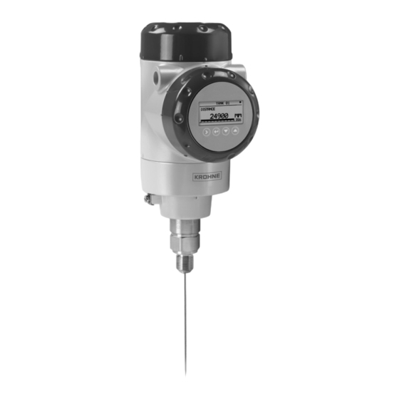
Guided radar (tdr) level meter
Hide thumbs
Also See for OPTIFLEX 2200 C/F:
- Supplementary instructions manual (32 pages) ,
- Supplementary instructions manual (24 pages)
Table of Contents
Advertisement
Quick Links
OPTIFLEX 2200 C/F
OPTIFLEX 2200 C/F
OPTIFLEX 2200 C/F
OPTIFLEX 2200 C/F
Guided Radar (TDR) Level Meter
Supplementary Instructions for IECEx applications
Supplementary Instructions for IECEx applications
Supplementary Instructions for IECEx applications
Supplementary Instructions for IECEx applications
© KROHNE 04/2013 - 4000861902 - AD IECEX OPTIFLEX2200 R02 en
Supplementary instructions
Supplementary instructions
Supplementary instructions
Supplementary instructions
Advertisement
Table of Contents

Related Manuals for KROHNE OPTIFLEX 2200 C/F


Summary of Contents for KROHNE OPTIFLEX 2200 C/F
- Page 1 Supplementary instructions Supplementary instructions Guided Radar (TDR) Level Meter Supplementary Instructions for IECEx applications Supplementary Instructions for IECEx applications Supplementary Instructions for IECEx applications Supplementary Instructions for IECEx applications © KROHNE 04/2013 - 4000861902 - AD IECEX OPTIFLEX2200 R02 en...
-
Page 2: Table Of Contents
CONTENTS OPTIFLEX 2200 C/F 1 General safety information 1.1 Scope of the document..................... 4 1.2 Device description ......................4 1.3 Standards and approvals....................4 1.4 Equipment protection levels (EPL)................... 5 1.4.1 Ex ia-approved devices ......................5 1.4.2 Ex dia / Ex ia tb-approved devices ..................5 1.4.3 Ex ic-approved devices ...................... - Page 3 CONTENTS OPTIFLEX 2200 C/F 5 Service 5.1 Periodic maintenance..................... 30 5.2 Keep the device clean..................... 30 5.3 Returning the device to the manufacturer..............30 5.3.1 General information......................30 5.3.2 Form (for copying) to accompany a returned device............31 04/2013 - 4000861902 - AD IECEX OPTIFLEX2200 R02 en...
-
Page 4: General Safety Information
GENERAL SAFETY INFORMATION OPTIFLEX 2200 C/F 1.1 Scope of the document These instructions are applicable only to the explosion-protection version of the TDR level transmitter. For all other data, use the Quick Start and Handbook. If you do not have these documents, please contact the nearest office or download them from the manufacturer's internet site. -
Page 5: Equipment Protection Levels (Epl)
GENERAL SAFETY INFORMATION OPTIFLEX 2200 C/F 1.4 Equipment protection levels (EPL) 1.4.1 Ex ia-approved devices The Ex ia-approved device is suitable for use in potentially explosive atmospheres of all flammable substances in Gas Groups IIA, IIB and IIC when fitted with appropriate options. It is certified for applications for which an EPL of Ga/Gb or Gb is necessary. -
Page 6: Iecex Nameplates
GENERAL SAFETY INFORMATION OPTIFLEX 2200 C/F 1.5 IECEx nameplates Compact version Figure 1-1: Compact version, Ex ia nameplate Figure 1-2: Compact version, Ex d ia / Ex ia tb nameplate 1 IECEx certification agency code 2 Types of device protection including approved Gas Groups and temperature classes (T6...T3 or T2 - depends on the... - Page 7 GENERAL SAFETY INFORMATION OPTIFLEX 2200 C/F Figure 1-3: Compact version, Ex ic nameplate 1 IECEx certification agency code 2 Types of device protection including approved Gas Groups and temperature classes (T6...T3 or T2 - depends on the probe type) and equipment protection level...
- Page 8 GENERAL SAFETY INFORMATION OPTIFLEX 2200 C/F Remote (Field) version Figure 1-4: Remote version, Ex ia nameplate on the converter housing Figure 1-5: Remote version, Ex ia nameplate on the probe housing 1 IECEx certification agency code 2 Types of device protection including approved Gas Groups, temperature classes (T6...T3 or T2 - depends on the probe...
- Page 9 GENERAL SAFETY INFORMATION OPTIFLEX 2200 C/F Figure 1-6: Remote version, Ex d / Ex ia tb nameplate on the converter housing Figure 1-7: Remote version, Ex ia nameplate on the probe housing 1 IECEx certification agency code 2 Types of device protection including approved Gas Groups, temperature classes (T6...T3 or T2 - depends on the probe...
- Page 10 GENERAL SAFETY INFORMATION OPTIFLEX 2200 C/F Figure 1-8: Remote version, Ex ic nameplate on the converter housing Figure 1-9: Remote version, Ex ic nameplate on the probe housing (fieldbus options only) 1 IECEx certification agency code 2 Types of device protection including approved Gas Groups, temperature classes (T6...T3 or T2 - depends on the probe...
-
Page 11: Installation
INSTALLATION OPTIFLEX 2200 C/F 2.1 Precautions 2.1.1 General notes WARNING! When you install the device, obey the conditions in the IECEx approval certificate. These conditions include: The special conditions for safe use. • The Essential Health and Safety Requirements. •... -
Page 12: Operating Conditions
INSTALLATION OPTIFLEX 2200 C/F 2.2 Operating conditions The allowable ambient temperature and corresponding flange temperature range for the device depends on the IEC equipment protection level (EPL) and temperature classes marked on the nameplate. 2.2.1 Ambient and flange temperature The IEC equipment protection level and temperature class give the ambient temperature and related flange temperature ranges for the device. - Page 13 INSTALLATION OPTIFLEX 2200 C/F Compact versions EPL Ga/Gb: Ex ia and Ex d ia devices Temperature Maximum ambient temperature Max. flange class temperature Ø2 mm / Ø0.08¨ Ø2 mm / Ø0.08¨ All other probe types single cable probe single cable probe...
- Page 14 INSTALLATION OPTIFLEX 2200 C/F Compact version EPL Gb: Ex ia and Ex d ia devices EPL Gc: Ex ic devices Temperature Maximum ambient temperature Max. flange class temperature Ø2 mm / Ø0.08¨ Ø2 mm / Ø0.08¨ All other probe types...
- Page 15 INSTALLATION OPTIFLEX 2200 C/F Remote (Field) versions (probe housing only) EPL Ga/Gb: Ex ia and Ex d ia devices Temperature Maximum ambient temperature Max. flange class temperature Ø2 mm / Ø0.08¨ Ø2 mm / Ø0.08¨ All other probe types single cable probe...
- Page 16 INSTALLATION OPTIFLEX 2200 C/F Temperature Maximum ambient temperature Max. flange class temperature Ø2 mm / Ø0.08¨ Ø2 mm / Ø0.08¨ All other probe types single cable probe single cable probe (HT version) (other versions) [°C] [°F] [°C] [°F] [°C] [°F] [°C]...
- Page 17 INSTALLATION OPTIFLEX 2200 C/F Compact and Remote (Field) versions EPL Da/Db, Db: Ex ia and Ex ia tb devices EPL Dc: Ex ic devices Maximum flange Maximum ambient temperature temperature Ø2 mm / Ø0.08¨ Ø2 mm / Ø0.08¨ All other probe types...
-
Page 18: Maximum Surface Temperature Of The Housing For Dust Applications
INSTALLATION OPTIFLEX 2200 C/F 2.2.2 Maximum surface temperature of the housing for dust applications WARNING! Equipment category 1/2 D, 2 D, 3 D or EPL Da/Db, Db, Dc: Ex ia, Ex ia tb and Ex ic devices only Equipment category 1/2 D, 2 D, 3 D or EPL Da/Db, Db, Dc: Ex ia, Ex ia tb and Ex ic devices only... -
Page 19: Electrical Connections
ELECTRICAL CONNECTIONS OPTIFLEX 2200 C/F 3.1 General notes WARNING! • De-energize the circuit. Use the applicable cable glands for the cable entry openings in the housing (M20×1.5 or • NPT). For the cable entry size, refer to the device nameplate. -
Page 20: How To Close The Terminal Compartment
ELECTRICAL CONNECTIONS OPTIFLEX 2200 C/F Equipment needed (not supplied) • 2.5 mm Allen wrench. INFORMATION! Ex i applications Ex i applications Ex i applications Ex i applications If you remove the terminal compartment cover, the device has a degree of ingress protection IP 20. -
Page 21: Terminal Tightening Capacity
ELECTRICAL CONNECTIONS OPTIFLEX 2200 C/F 3.3 Terminal tightening capacity The terminal tightening capacity for the current output terminal and the communication cable is: Type of wire Terminal tightening capacity [mm²] [AWG] Rigid Flexible 3.4 Equipotential bonding system Compact version There is a terminal at the bottom of the converter that can be used as an equipotential bonding conductor. -
Page 22: Ex Ia Equipment
ELECTRICAL CONNECTIONS OPTIFLEX 2200 C/F 3.5 Ex ia equipment 3.5.1 How to connect the electrical cables Cable entries are supplied on customer demand. If you supply the cable entries, this part must have a degree of ingress protection IP≥6x (IEC 60529). -
Page 23: Electrical Schematic
ELECTRICAL CONNECTIONS OPTIFLEX 2200 C/F 3.5.4 Electrical schematic Level transmitter with the 4...20 mA passive - HART output option Figure 3-5: Electrical schematic for Ex ia-approved equipment with the 4...20 mA passive - HART output option Level transmitter with the FOUNDATION™ fieldbus or PROFIBUS PA output option Figure 3-6: Electrical schematic for Ex ia-approved equipment with the FOUNDATION™... -
Page 24: Ex D Ia / Ex Ia Tb Equipment
ELECTRICAL CONNECTIONS OPTIFLEX 2200 C/F 3.6 Ex d ia / Ex ia tb equipment 3.6.1 General notes Ex d ia- and Ex ia tb-approved equipment have two separate compartments. The electronics in the electronics block compartment are Ex ia-approved and the terminals compartment is Ex d / Ex t-approved. -
Page 25: How To Connect The Electrical Cables
ELECTRICAL CONNECTIONS OPTIFLEX 2200 C/F 3.6.2 How to connect the electrical cables Cable entries are supplied on customer demand. If you supply the cable entries, this part must have a degree of ingress protection IP≥6x (IEC 60529). WARNING! Use only Ex d-approved cable entries and plugs for Ex d applications. Use only Ex t-approved cable entries and plugs for Ex t applications. - Page 26 ELECTRICAL CONNECTIONS OPTIFLEX 2200 C/F Level transmitter with the 4...20 mA passive - HART output option Figure 3-9: Electrical schematic for Ex d ia / Ex ia tb-approved equipment (with galvanic isolation) Figure 3-10: Electrical schematic for Ex d ia / Ex ia tb-approved equipment (without galvanic isolation)
-
Page 27: Ex Ic Equipment
ELECTRICAL CONNECTIONS OPTIFLEX 2200 C/F 3.7 Ex ic equipment 3.7.1 How to connect the electrical cables Cable entries are supplied on customer demand. If you supply the cable entries, this part must have a degree of ingress protection IP≥6x (IEC 60529). -
Page 28: Electrical Schematic
ELECTRICAL CONNECTIONS OPTIFLEX 2200 C/F 3.7.4 Electrical schematic Level transmitter with the 4...20 mA passive - HART output option Figure 3-12: Electrical schematic for Ex ic-approved equipment with the 4...20 mA passive - HART output option Level transmitter with the FOUNDATION™ fieldbus or PROFIBUS PA output option Figure 3-13: Electrical schematic for Ex ic-approved equipment with the FOUNDATION™... -
Page 29: Start-Up
START-UP OPTIFLEX 2200 C/F WARNING! Make sure that it is safe to supply electrical power. Do a start-up check: • Are the wetted components (gasket, flange and probe) resistant to corrosion by the tank product? • Does the information given on the nameplate agree with the application? •... - Page 30 SERVICE OPTIFLEX 2200 C/F 5.1 Periodic maintenance No maintenance is necessary. 5.2 Keep the device clean Obey these instructions: • Keep the thread of the terminal compartment cover clean. • If dirt collects on the device, clean it. 5.3 Returning the device to the manufacturer 5.3.1 General information...
- Page 31 SERVICE OPTIFLEX 2200 C/F 5.3.2 Form (for copying) to accompany a returned device Company: Address: Department: Name: Tel. no.: Fax no.: Manufacturer's order no. or serial no.: The device has been operated with the following medium: This medium is: water-hazardous...
- Page 32 • Measuring systems for the marine industry Head Office KROHNE Messtechnik GmbH Ludwig-Krohne-Str. 5 47058 Duisburg (Germany) Tel.:+49 (0)203 301 0 Fax:+49 (0)203 301 10389 info@krohne.de The current list of all KROHNE contacts and addresses can be found at: www.krohne.com...
Need help?
Do you have a question about the OPTIFLEX 2200 C/F and is the answer not in the manual?
Questions and answers