Table of Contents
Advertisement
Quick Links
Advertisement
Table of Contents

Subscribe to Our Youtube Channel
Related Manuals for Cole Parmer Jenway 76 Series


Summary of Contents for Cole Parmer Jenway 76 Series
- Page 1 Spectrophotometer 7410,7415 and 7615 Instruction Manual JEN0001 / Version 1.2...
-
Page 2: Table Of Contents
Contents Section 1 - Introduction ................. 6 General Description ....................... Important Safety Advice ....................1.3 Symbols Defined ......................Electrical Requirements ....................Section 2 - Installation ................... 8 Unpacking ........................Installation Conditions ....................Overview ........................Section 3 - Theory and Practice of Spectroscopy Measurement ....Theory of Spectroscopy Measurement ................ - Page 3 Method Set up ......................22 6.1.1 Selecting a Wavelength ................... 22 6.1.2 Using a Factor......................22 6.1.3 Using a Standard ....................23 6.1.4 Selecting Concentration Units ................... 23 Calibration ........................23 6.2.1 Calibrating to a Factor ..................... 24 6.2.2 Calibrating to a Standard ..................24 Sample Measurement ....................
- Page 4 9.1.3 Setting the Measurement Time Interval ..............37 9.1.4 Setting Lag Time ..................... 37 9.1.5 Selecting Absorbance or % Transmittance..............37 9.1.6 End Point Concentration ..................37 Calibration ........................38 Sample Measurement ....................38 Data Analysis ........................ 40 Section 10 - Multi-Wavelength............... 10.1 Method Set up ......................
- Page 5 12.2 Installing the Accessories ....................47 12.2.1 Passive Accessories ....................47 12.2.2 Active Accessories ....................48 12.2.2.1 Installing Automatic 8 Cell Turret ................ 49 12.3 Using the Accessories ....................50 12.3.1 Automatic 8 Cell Turret .................... 50 12.3.1.1 Automatic 8 Cell Turret - Manual Mode ............... 50 12.3.1.2 Automatic 8 Cell Turret - Automatic Mode ............
-
Page 6: Section 1 - Introduction
Section 1 - Introduction Thank you for purchasing this Jenway product. To get the best performance from the equipment, and for your own safety, please read these instructions carefully before use. If the equipment is not used in the manner described in this manual and with accessories other than those recommended by the manufacturer, the protection provided may be impaired. -
Page 7: Electrical Requirements
Electrical Requirements THIS INSTRUMENT MUST BE GROUNDED Before connection please ensure that the line supply corresponds to the power requirements below: Power Supply requirements 65 W 100 V - 230 V ~ 50/60 Hz The equipment is provided with a power supply unit and three power cables consisting of a UK 3-pin and a “Schuko” 2-pin plug for 230 V installations and a NEMA 5-15 plug for 120 V installations. -
Page 8: Section 2 - Installation
Section 2 - Installation Unpacking Before discarding the packaging check that all parts are present and correct. 1 7410 / 7415 / 7615 2 Instruction manual 3 UK power lead 4 EU power lead 5 US power lead 6 Power supply unit Installation Conditions When the equipment is used for the first time or moved to a different environmental temperature, it is important to allow the equipment to equalise to the ambient temperature. -
Page 9: Overview
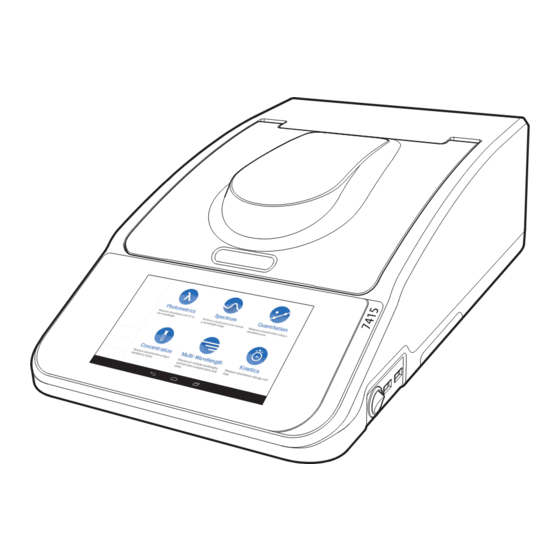
Overview Main View Open and close catch Colour touchscreen and user interface Removable panel for sipper accessory 2 x USB Type A ports On/Off power switch Rear View Ethernet (RJ-45) port USB Type B port Power inlet socket Underneath View Lamp holder cover Refer to Section 13.2 for instructions on how to remove and replace the lamp. -
Page 10: Section 3 - Theory And Practice Of Spectroscopy Measurement
Section 3 - Theory and Practice of Spectroscopy Measurement Theory of Spectroscopy Measurement UV-visible spectroscopy is the measurement of the absorbance of light at a specific wavelength in a sample. This is used to identify the presence and concentration of molecular entities within the sample. The Beer-Lambert law is used to relate the absorption of light to the properties of the sample through which the light is travelling through. The Beer-Lambert law states that: A = Ɛ... -
Page 11: Spectroscopy Measurement
Spectroscopy Measurement There are four main components of a spectrophotometer. These are a light source to emit a high and constant amount of energy over the full wavelength range; a method for separating the light into discreet wavelengths; a sample holder and a light detector. The optical layout of the 7410 and 7415 spectrophotometers is shown below: Entrance Slit Grating... -
Page 12: Good Practice Guidelines
Good Practice Guidelines 1. For optimum performance all spectrophotometers should be sited in a clean, dry, dust free atmosphere. When in use ambient temperature and light levels should remain as constant as possible. 2. If required adherence to Standard Operating Procedures (SOP) and Good Laboratory Practice (GLP) should be monitored with regular calibration checks and a suitable Quality Control (QC) programme. - Page 13 9. Deviations from the Beer-Lambert Law may occur at high and low concentrations giving non-linear response during sample concentration measurements. For all new methods a linear range should be defined by the preparation of a calibration curve. The quantitation mode may be used to construct such a curve against which sample results are automatically measured. 10. Cuvettes and sample holders must be filled to a minimum level which covers the light path. All Jenway spectrophotometers have a beam height of 15mm.
-
Page 14: Section 4 - Instrument Set Up
Section 4 - Instrument Set up Start up Screen The power up screen is shown below: Navigation The main menu is shown below: These spectrophotometers are controlled solely through the touchscreen interface of the equipment and follow a basic Android user interface. If the number of options available in a menu exceeds the number that can be displayed on the screen, swipe to the left to view the other modes. - Page 15 The main menu screen provides access to all Measurement modes, Methods, Results and the Settings menu. Additional icons are displayed when the unit is connected to a network and if an active accessory is installed. The settings menu enables access to Instrument status, Measurement settings, Network connections Storage and Service settings.
-
Page 16: Methods
Methods Touch to access methods that have been saved. Touch the required method to view the details of the method set up. You will then be able to delete, upload, export, edit or run the selected method. See section 11 for more information. -
Page 17: 4.5.1.2 Setting The Time
4.5.1.2 Setting the Time To set the instrument time touch .Touch and move the clock hand to the correct hour position, repeat the same process for minutes, select AM or PM and touch to apply. Touching will return to the instrument settings screen without altering the time. -
Page 18: 4.5.1.4 Setting The Time Zone
4.5.1.4 Setting the Time Zone To set the instrument time zone touch . Scroll up or down to locate the required time zone and touch next to the required time zone to apply. 4.5.2 Measurement Settings Touch to select options for autosave results and the favourites panel. Results can be saved automatically to the instrument’s internal memory by sliding the button to the position. -
Page 19: Network Connections
4.5.3 Network Connections Touch to view available network connections. Options include Ethernet (RJ-45), IP configuration, connection status and CPLive. 4.5.4 Storage Touch to view the amount of available storage on the internal memory of the spectrophotometer. If a USB memory stick is inserted the amount of free space on the USB stick will also be shown. 4.5.5 Service Settings Service settings is for service engineers only... -
Page 20: Section 5 - Photometrics
Section 5 - Photometrics The photometrics measurement mode enables simple measurements of absorbance and % transmittance to be performed. The sample is measured at one wavelength and at one point in time. There are no post measurement calculations available in this measurement mode. Touch the Photometrics icon on the main menu to enter this measurement mode. -
Page 21: Calibration
Calibration The calibration must be performed at the same wavelength at which the sample will be measured. Insert a cuvette containing the blank solution into the sample chamber and close the instrument lid. Touch the icon. This sets the instrument to zero absorbance and 100% transmittance . -
Page 22: Section 6 - Concentration
Section 6 - Concentration The concentration measurement mode enables sample concentrations to be calculated using a standard of a known concentration or a known factor. The sample is measured at one wavelength at one point in time. There are no post measurement calculations available in this measurement mode. Touch the Concentration icon on the main menu to enter this measurement mode. -
Page 23: Using A Standard
6.1.3 Using a Standard If the factor is not known a standard of known concentration can be measured to calculate concentration. Touch to select this option and disable the use factor option. To enter the concentration of the known standard touch the value under standard and use the keypad to enter the required concentration value. -
Page 24: Calibrating To A Factor
6.2.1 Calibrating to a Factor If a Factor has been entered, only a blank calibration is required. Insert a cuvette containing the blank solution into the sample chamber and close the instrument lid. Touch the icon and the instrument will calibrate to zero absorbance and 100% transmittance . -
Page 25: Sample Measurement
Sample Measurement It is not possible to perform sample measurements before the instrument has been calibrated at the selected wavelength. 6.3.1 Measuring a Sample After Calibrating to a Factor Remove the cuvette containing the blank solution and place a cuvette containing the sample to be measured in the sample chamber. -
Page 26: Section 7 - Spectrum
Section 7 - Spectrum The spectrum measurement mode enables measurements of absorbance or % transmittance over a range of wavelengths to be performed. The absorbance or % transmittance at each wavelength is plotted graphically. Post measurement tools such as peaks and valleys analysis and area under the graph can be performed. This operating mode can be used to partially characterise a sample. -
Page 27: Setting The Scan Interval
7.1.2 Setting the Scan Interval This function enables the interval between wavelengths measured in the spectrum scan to be set. The scan interval can be altered to 1, 2, 5 or 10nm by touching the value below scan interval . Select the required scan interval from the available options. -
Page 28: Data Analysis
Once the spectrum scan is completed it is possible to analyse the spectrum scan. Post measurement tools include peaks and valleys and area under the curve. To analyse the data touch Data Analysis Touching the spectrum scan will open a sliding cursor . -
Page 29: Area Under Curve
7.4.2 Area Under Curve To view the area under the curve touch . The default mode is baseline. To change this between baseline and tangent, touch to select the required measurement mode. Repeat touches will cycle between the two options. 7.4.2.1 Area Under Curve - Baseline Mode Baseline will calculate the area under the curve between the two sliding cursors . -
Page 30: 7.4.2.2 Area Under Curve - Tangent Mode
7.4.2.2 Area Under Curve - Tangent Mode Tangent will calculate the area under the curve from the point where each of the two sliding cursors crosses the spectrum scan. Slide the cursors to the select the area required. You can also use the arrows to move the selected area. -
Page 31: Section 8 - Quantitation
Section 8 - Quantitation The quantitation measurement mode enables sample concentrations to be calculated using a standard curve. In this mode a number of standard solutions covering a range of known concentrations are measured at a set wavelength. The absorbance or % transmittance of these solutions is plotted to create a standard curve. Once the standard curve has been created a sample of unknown concentration can be measured and the concentration calculated using the standard curve. -
Page 32: Selecting Number Of Replicates
8.1.2 Selecting Number of Replicates To select the number of repeat measurements of a calibration standard touch . Touch the circle adjacent to the required unit of replicates to apply and return to the method set up. If 2 or more replicates are selected, becomes active. -
Page 33: Measuring Calibration Standards
Measuring Calibration Standards The measured standards are used to create a calibration curve. If there is only one standard available the concentration measurement mode should be used. Touch to add the first standard. Touch to use keypad to enter the concentration value required for that standard. Touch apply. -
Page 34: Standard Curve
number of times. Touch to save the absorbance results for the standard. Touch to add another standard and enter the concentration value for that standard. This time a blank is not required so the Standard icon is active straight away. Place the known standard solution into the sample chamber and close the instrument lid. -
Page 35: Sample Measurement
Specific points can be selected on the graph by touching the graph, a sliding cursor will appear. It is possible to move the cursor by dragging left or right. The curve fit algorithm can be changed by touching . Select between linear through zero, linear, quadratic through zero and quadratic. The curve statistics are also displayed for the curve fit chosen. For example if the curve fit is y = mx+c the curve statistics displayed will be the gradient of the line (m), constant (c) and correlation coefficient (r²). Once all the standards have been measured touch and then the unknown samples can be measured. Sample Measurement Place a cuvette containing the sample to be measured in the sample holder. Close the instrument lid and touch the . -
Page 36: Section 9 - Kinetics
Section 9 - Kinetics The kinetics measurement mode enables the absorbance or % transmittance of an active molecule to be measured over a set time; for example, enzyme activity. The absorbance or % transmittance is measured at regular time intervals at one wavelength over time. The results are plotted on a graph to show the change in absorbance or % transmittance over time. -
Page 37: Setting The Kinetics Measurement Time
required wavelength. Touch to apply the entered wavelength and return to the method set up. 9.1.2 Setting the Kinetics Measurement Time To set the total kinetics measurement time touch and enter the required run time. Scroll up or down beneath Hours, Minutes, Seconds to select the required time and touch to apply. -
Page 38: Calibration
Touch to apply the concentration parameters and return to method set up. Calibration The calibration must be performed at the same wavelength at which the sample will be measured. Insert a cuvette containing the blank solution into the sample chamber and close the instrument lid. Touch the icon. - Page 39 holder. Close the instrument lid and touch the icon. If a lag time has been set the instrument will count down the lag time before the kinetics run starts. If no lag time has been set the kinetics run starts straight away and a live kinetics run is shown on the screen. If the kinetics run needs to be stopped touch . A warning message will appear asking for confirmation to stop the kinetics run.
-
Page 40: Data Analysis
in the same way. If the wavelength is adjusted between sample measurements then the instrument must be calibrated again before more samples can be measured. Data Analysis Following the completion of the kinetics measurements it is possible to analyse the data. These include the rate of change and end point concentration. To analyse the data touch The rate of change of absorbance over time can be viewed for the entire kinetics run or for selected parts of the kinetics run. -
Page 41: Section 10 - Multi-Wavelength
Section 10 - Multi-Wavelength The multi-wavelength measurement mode enables measurements of absorbance and % transmittance to be performed, as well as concentration and ratios to be calculated. The sample can be measured at four different wavelengths and at one point in time. Touch the Multi-wavelength icon on the main menu to enter this measurement mode. -
Page 42: Equation Parameters
10.1.2 Equation Parameters To select the required equation parameters, touch the The type of equation can be selected from several options. Touch and select the required equation from the menu. If no equation is selected then the factor and units options will be disabled. Touch to apply the equation parameters or touch to return to the method set up without saving any... -
Page 43: 10.1.2.1 Entering A Factor
10.1.2.1 Entering a Factor If the equation selected requires Factors to calculate the concentration result, the factors will also need to be entered. Touch and use the keypad to enter the required factor. Touch to apply the entered factor. Touch to apply the factor or touch to return to the method set up without saving any changes. -
Page 44: Calibration
10.2 Calibration The calibration must be performed at the same wavelengths at which the sample will be measured. Insert a cuvette containing the blank solution into the sample chamber and close the instrument lid. Touch the icon. This sets the instrument to zero absorbance and 100% transmittance. 10.3 Sample Measurement It is not possible to measure a sample before the instrument has been calibrated at the selected wavelengths.Once... -
Page 45: Section 11 - Saving, Loading, Deleting And Printing
Section 11 - Saving, Loading, Deleting and Printing 11.1 Saving Methods 11.1.1 Saving Methods to Internal Memory On each method set up screen there is an overflow icon . Touch and then touch to save the entered method parameters. Use the keypad to enter method name and touch to apply the name, touch Save 11.1.2 Saving Methods to CPLive... -
Page 46: Saving Results
option to 11.4 Saving Results 11.4.1 Saving Results to Internal Memory After a measurement has been performed, touch 11.4.2 Saving Results to CPLive You can save your results to CPLive via the home or results screen. On the home screen touch . -
Page 47: Section 12 - Accessories And Spare Parts
Results shown as an example only. Section 12 - Accessories and Spare Parts 12.1 Optional Accessories Please visit www.jenway.com for a full list of available accessories. 12.2 Installing the Accessories WARNING: Before installing any accessories, ensure that the equipment is cool, and disconnect from the power supply There are two types of accessories which can be fitted in the sample chamber – passive (non-powered) or active (powered) accessories. The range of passive accessories includes 10 x 10mm single cuvette holders, adjustable path length (10 to 100 mm) cuvette holders, test tube holders and micro-cuvette holders. -
Page 48: Active Accessories
accessory simply place the accessory in the correct orientation, align the thumb screw and tighten to fix in place. 12.2.2 Active Accessories Unscrew the thumb screw to undo the passive accessory. Lift out the passive accessory. Unscrew the screws 1 to 4 and lift out the metal base panel. This will expose the bottom of the sample chamber and the power supply connection needed to operate the active accessories. -
Page 49: 12.2.2.1 Installing Automatic 8 Cell Turret
12.2.2.1 Installing Automatic 8 Cell Turret Take the 8 cell turret base plate. Connect the power supply in the bottom of the sample chamber to the connector in the underside of the base plate. Place the base plate in the sample chamber. Replace screws 1 to 4. Take the 8 cell carousel and place on top of the motor, taking care to align the three ball bearings with the grooves on the motor shaft. -
Page 50: Using The Accessories
12.3 Using the Accessories 12.3.1 Automatic 8 Cell Turret When the automatic 8 cell turret is installed the active accessory icon is displayed on the home or measurement method set up screen. The automatic 8 cell turret can be used in either a manual or automatic mode. To select mode, touch on the home or measurement method set up screen. - Page 51 The turret will need to move to take its next measurement. To do this touch to change the cell position. You can also change the cell position by touching and then selecting the required position . Touch to return to the method set up screen and touch to measure the sample.
-
Page 52: 12.3.1.2 Automatic 8 Cell Turret - Automatic Mode
12.3.1.2 Automatic 8 Cell Turret - Automatic Mode Set to automatic mode. Select the measurement mode you require (photometrics has been used as an example only), the automatic 8 cell turret will automatically move to position 0. Set up the required measurement parameters. Insert the cuvette containing the blank solution into turret position 0 followed by the cuvettes containing the samples into turret positions 1 to 7 and close the instrument lid. - Page 53 Touch and the instrument will automatically set the instrument to zero absorbance and 100% transmittance. Once the calibration has been performed the turret will automatically measure each sample. Once all of the samples have been measured the results will be displayed. Touch the corresponding cell position to view the results. At this point you will be able to...
-
Page 54: 12.3.1.3 Automatic 8 Cell Turret - Supporting Creation Of A Standard Curve In Quantitation
12.3.1.3 Automatic 8 Cell Turret - Supporting Creation of a Standard Curve in Quantitation This option is currently unavailable. 12.4 Spare Parts Please contact your local sales specialist or email cpspares@coleparmer to enquire about available spares. -
Page 55: Section 13 - Maintenance, Servicing And Cleaning
Section 13 - Maintenance, Servicing and Cleaning WARNING: Before attempting any maintenance, servicing or cleaning, ensure that the equipment has been allowed to cool down. WARNING: Ensure the equipment is disconnected from the power supply before attempting any maintenance, servicing or cleaning. WARNING: Do not work within the equipment while the lamp is ON as exposure to the high intensity light can cause injury to your eyes. - Page 56 NOTE: In the event of this equipment or any part of the unit becoming damaged or requiring service, the item(s) should be returned to the manufacturer for repair accompanied by a decontamination certificate. Copies of the Certificate are available from the Distributor/Manufacturer. At the end of its service life, the product must be accompanied by a Decontamination Certificate.
-
Page 57: Lamp Replacement
13.2 Lamp Replacement 13.2.1 Tungsten Halogen Lamp Replacement This option is only valid for the 7410 Spectrophotometers. We recommend the equipment is turned onto its side to allow easy access to the lamp holder cover located on the underneath of the equipment (refer to section 2.3). Wear ‘lint free’ protective gloves when replacing the lamp to prevent marking the lamp with finger prints. -
Page 58: Xenon Lamp Module Replacement
Place the equipment back in its correct orientation. XI. Reconnect the power supply, turn the equipment on and allow to self-calibrate with the new lamp. For further instructions refer to the service manual. 13.2.2 Xenon Lamp Module Replacement This option is only valid for the 7415 Spectrophotometers and must only be done by an accredited service engineer (refer to section 13.3). -
Page 59: Section 15 - Technical Specification
Section 15 - Technical Specifications 15.1 General Specification 7410/7415/7615 7410 7415 7615 Wavelength Range (nm) 320 to 1000 198 to 1000 198 to 1000 Wavelength Step (nm) Wavelength Accuracy (nm) ± 2 ± 2 ± 1 Wavelength Reproducibility (nm) ± 0.5 ±... -
Page 60: Weights And Dimensions
15.2 Weights and Dimensions Weight 9.0kg 280mm 500mm... -
Page 61: Section 16 - Troubleshooting
Section 16 - Troubleshooting During initial power on self-test (POST) The following errors can appear during the initial self-test. A hardware problem has been detected. You may continue to use the instrument but calibration data may have been affected causing any readings to be inaccurate. Contact Cole-Parmer support and quote error code 101. - Page 62 During scanning (blank, standard or sample) The following errors can appear whenever the optical hardware is used. Each error message will be attached to the activity which was just performed. The error messages are displayed as a notification on screen with an option to display more information about the error. If multiple errors have been detected, they will be displayed in the more information. The ‘blank / standard / sample’...
-
Page 63: Section 17 - Glossary Of Icons
Section 17 - Glossary of Icons Sample warning Cancel Save Analysis Unused turret position Search Area under curve Analysis Delete Settings Peaks and valleys Select all Spectrum peak Upload to CPLive Deselect favourite Spectrum valley Concentration Favourite Standard complete Kinetics Load method Stop Multi-wavelength... -
Page 64: Index
Index Instrument Status ............16 Accessories and Spare Parts .............47 Active Accessories ..............48 Introduction ...............6 Automatic 8 Cell Turret ............50 Automatic 8 Cell Turret - Automatic Mode ......52 Kinetics ..............36 Automatic 8 Cell Turret - Manual Mode ......50 Calibration ............38 Supporting Creation of a Standard Curve in Quantitation ..54 Data Analysis ...........40 End Point Concentration........37 Beer-Lambert law ..............10... - Page 65 Packaging Material ............58 Area Under Curve - Tangent Mode ......30 Calibration ...............27 Passive Accessories ............47 Data Analysis ............28 Photometrics ..............20 Method Set up ............26 Calibration ...............21 Method Set up ............20 Peaks and Valleys .............28 Sample Measurement ..........21 Sample Measurement ..........27 Selecting a Wavelength ..........20 Selecting Absorbance or % Transmittance ....
-
Page 66: Declaration Of Conformity
Declaration of Conformity This product meets applicable and so we cannot guarantee that interference will not harmonized standards for radio frequency occur in practice. Where there is a possibility that injury, interference and may be expected not to damage or loss might occur if equipment malfunctions interfere with, or be affected by, other equipment with due to radio frequency interference, or for general similar qualifications. - Page 67 Declaration of Conformity is also available to view online at www.jenway.com...
- Page 68 Cole-Parmer Ltd. Beacon Road, Stone, Staffordshire, ST15 0SA, United Kingdom Tel: +44 (0)1785 812121 Email: cpinfo@coleparmer.com Web: www.jenway.com...
Need help?
Do you have a question about the Jenway 76 Series and is the answer not in the manual?
Questions and answers