Terex Genie GS-1930 Operator's Manual
Hide thumbs
Also See for Genie GS-1930:
- Service and repair manual (341 pages) ,
- Service manual (198 pages) ,
- Operator's manual (107 pages)

Related Manuals for Terex Genie GS-1930


Summary of Contents for Terex Genie GS-1930
- Page 1 Operator’s Manual GS-1530 Australia GS-1532 GS-1930 GS-1932 with with GS-2032 Maintenance Maintenance Information Information GS-2632 GS-3232 GS-2046 GS-2646 Fifth Edition Fourth Printing GS-3246 Part No. 114423...
-
Page 2: Table Of Contents
Fourth Printing, May 2018 Internet: www.genielift.com "Genie" is a registered trademark of e-mail: techpub@genieind.com Terex South Dakota, Inc. in the U.S.A. and many other countries. "GS" is a trademark of Terex South Dakota, Inc. Printed on recycled paper Printed in U.S.A. -
Page 3: Introduction
Operator's Manual Fifth Edition • Fourth Printing Introduction Owners, Users and Operators: Genie appreciates your choice of our machine for your application. Our number one priority is user safety, which is best achieved by our joint efforts. We feel that you make a major contribution to safety if you, as the equipment users and operators: Danger... - Page 4 Operator's Manual Fifth Edition• Fourth Printing Introduction Hazard Classification Intended Use Genie uses symbols, color coding and signal This machine is intended to be used only to lift words to identify the following: personnel, along with their tools and materials to an aerial work site.
-
Page 5: Symbol And Hazard Pictorials
Operator's Manual Fifth Edition • Fourth Printing Symbol and Hazard Pictorials Definitions Read the Read the operator’s service manual manual Crush hazard Crush hazard Collision hazard Tip-over hazard Tip-over hazard Tip-over hazard Tip-over hazard Electrocution hazard Electrocution Skin injection hazard Explosion hazard Fire hazard hazard... - Page 6 Operator's Manual Fifth Edition• Fourth Printing Symbol and Hazard Pictorials Definitions Batteries used as Grounded AC Replace damaged counterweights Chock the wheels Release brakes 3-wire only wires and cords Lanyard Transport No smoking Wheel load Tiedown attachment point diagram Pressure rating for Voltage rating for air line to platform power to platform...
-
Page 7: General Safety
Operator's Manual Fifth Edition • Fourth Printing General Safety Safety signs and locations Decals with words DANGER Failure to read, understand and obey the operator's manual and the following safety rules will result in death or serious injury. Improper Use Hazard Tip-over Hazards Do not use machine on a moving or mobile surface or vehicle. - Page 8 Operator's Manual Fifth Edition• Fourth Printing General Safety Safety signs and locations DANGER Engage safety arm Crushing Hazard See service before Death or serious injury can manual. performing result from contact with maintenance moving scissor arms. or repair. 82561 B WARNING DANGER Crushing hazard...
- Page 9 Operator's Manual Fifth Edition • Fourth Printing General Safety Safety signs and locations 114385 DANGER DANGER Maintain required clearance. Line voltage Required clearance 0 to 50KV 10 ft 3.05 m Electrocution Hazard 50KV to 200KV 15 ft 4.60 m Death or injury can result from contacting electric power Crushing hazard lines.
-
Page 10: Personal Safety
Operator's Manual Fifth Edition• Fourth Printing Personal Safety Fall Protection Personal fall protection equipment (PFPE) is not required when operating this machine. If PFPE is required by job site or employer rules, the following shall apply: All PFPE must comply with applicable governmental regulations, and must be inspected and used in accordance with the manufacturer’s instructions. -
Page 11: Work Area Safety
Operator's Manual Fifth Edition • Fourth Printing Work Area Safety Tip-over Hazards Electrocution Hazards Occupants, equipment and materials must not This machine is not electrically insulated and will exceed the maximum platform capacity or the not provide protection from contact with or maximum capacity of the platform extension. - Page 12 Operator's Manual Fifth Edition• Fourth Printing Work Area Safety Do not raise the platform unless the machine is on winds. Do not increase the surface area of the a firm, level surface. platform or the load. Increasing the area exposed to the wind will decrease machine stability.
- Page 13 Operator's Manual Fifth Edition • Fourth Printing Work Area Safety Do not push off or pull toward any object outside of Do not replace items critical to machine stability the platform. with items of different weight or specification. Do not use batteries that weigh less than the original equipment.
- Page 14 Operator's Manual Fifth Edition• Fourth Printing Work Area Safety If equipped with outriggers Fall Hazards Do not set the machine up where it cannot be The guard rail system provides fall protection. If leveled using only the outriggers. occupants of the platform are required to wear Do not adjust the outriggers while the platform is personal fall protection equipment (PFPE) due to raised.
- Page 15 Operator's Manual Fifth Edition • Fourth Printing Work Area Safety Check the work area for overhead obstructions or Bodily Injury Hazard other possible hazards. Do not operate the machine with a hydraulic oil or air leak. An air leak or hydraulic leak can penetrate and/or burn skin.
- Page 16 Operator's Manual Fifth Edition• Fourth Printing Work Area Safety Battery Safety Electrocution / Burn Hazards Connect the battery charger to a Burn Hazards grounded, AC 3-wire electrical outlet only. Batteries contain acid. Always wear protective clothing and Inspect daily for damaged eye wear when working with cords, cables and wires.
-
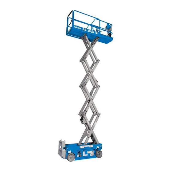
Page 17: Legend
Operator's Manual Fifth Edition • Fourth Printing Legend 1 Platform guard rails GS-1530 2 Lanyard anchorage point GS-1532 3 Air line to platform (optional) GS-1930 4 Manual storage container GS-1932 5 Platform controls 6 Platform extension 7 Transport tie-down 8 Steer tire 9 Pothole guard 10 LED diagnostic readout 11 Ground controls... - Page 18 Operator's Manual Fifth Edition• Fourth Printing Legend GS-2032 1 Platform guard rails 2 Lanyard anchorage point GS-2632 3 Air line to platform (optional) GS-3232 4 Outrigger controls - GS-3232 models 5 Platform controls 6 Platform extension 7 Manual storage container 8 Auxiliary lowering knob 9 Transport tie-down 10 Steer tire...
- Page 19 Operator's Manual Fifth Edition • Fourth Printing Legend GS-2046 1 Platform guard rails 2 Lanyard anchorage point GS-2646 3 Air line to platform (optional) GS-3246 4 Manual storage container 5 Platform controls 6 Platform extension 7 Auxiliary lowering knob 8 Transport tie-down 9 Steer tire 10 Pothole guard 11 LED diagnostic readout...
-
Page 20: Controls
Operator's Manual Fifth Edition• Fourth Printing Controls Ground Control Panel 4 Platform up/down toggle switch 1 7 amp breaker for electric circuits Move the switch up and the platform 2 Key switch for platform/off/ground selection will raise. Move the switch down and Turn the key switch to the platform position the platform will lower. - Page 21 Operator's Manual Fifth Edition • Fourth Printing Controls Outrigger Control Panel (GS-3232) 1 Lift enable indicator 4 Function enable button Turns green to indicate that the up/down Press and hold the button to activate the function can be operated. outrigger extend or outrigger retract button. 2 Lift error indicator light 5 Outrigger extend button.
- Page 22 Operator's Manual Fifth Edition• Fourth Printing Controls Platform Control Panel 1 Thumb rocker switch for steer functions 5 LED 2 Drive speed button 6 Lift function select button 3 Drive function select button 7 Horn button 4 Red Emergency Stop button 8 Proportional control handle and function enable switch for lift and drive functions GS-30 •...
- Page 23 Operator's Manual Fifth Edition • Fourth Printing Controls Platform Control Panel 7 Horn Button 1 Thumb rocker switch for steer functions Push the horn button and the horn will sound. Release the horn button and the horn will stop. Press the thumb rocker switch in either direction to activate steer function.
-
Page 24: Inspections
Operator's Manual Fifth Edition• Fourth Printing Inspections Pre-operation Inspection Fundamentals It is the responsibility of the operator to perform a pre-operation inspection and routine maintenance. The pre-operation inspection is a visual inspection Do Not Operate Unless: performed by the operator prior to each work shift. The inspection is designed to discover if anything You learn and practice the principles of safe is apparently wrong with a machine before the... - Page 25 Operator's Manual Fifth Edition • Fourth Printing Inspections Pre-operation Inspection Be sure that the operator’s, safety and Pothole guards responsibilities manuals are complete, legible Platform extension and in the storage container located in the platform. Scissor pins and retaining fasteners ...
- Page 26 Operator's Manual Fifth Edition• Fourth Printing Inspections Function Test Fundamentals The function tests are designed to discover any malfunctions before the machine is put into service. The operator must follow the step-by-step instructions to test all machine functions. A malfunctioning machine must never be used. If Do Not Operate Unless: malfunctions are discovered, the machine must be tagged and removed from service.
- Page 27 Operator's Manual Fifth Edition • Fourth Printing Inspections 1 Select a test area that is firm, level and free of 8 Activate the up function. obstruction. Result: The platform should raise. 2 Be sure the battery pack is connected. 9 Activate the down function. At the Ground Controls Result: The platform should lower.
- Page 28 Operator's Manual Fifth Edition• Fourth Printing Inspections Test the Function Enable Switch 25 Depress the thumb rocker switch on top of the control handle in the direction identified by the 16 Do not hold the function enable switch on the blue triangle on the control panel.
- Page 29 Operator's Manual Fifth Edition • Fourth Printing Inspections Test the Tilt Sensor Operation Test the Pothole Guards Note: Perform this test from the ground with the Note: The pothole guards should automatically platform controller. Do not stand in the platform. deploy when the platform is raised.
- Page 30 Operator's Manual Fifth Edition• Fourth Printing Inspections Test the Outrigger System 50 Press and hold the function enable switch on the control handle. 44 Press the lift function select button. 51 Slowly move the control handle in the direction 45 Press and hold the function enable switch on the indicated by the blue arrow.
- Page 31 Operator's Manual Fifth Edition • Fourth Printing Inspections Fundamentals The workplace inspection helps the operator determine if the workplace is suitable for safe machine operation. It should be performed by the operator prior to moving the machine to the workplace. Do Not Operate Unless: It is the operator's responsibility to read and remember the workplace hazards, then watch for...
- Page 32 Label - ECM Fault Codes 97772 Platform Control Panel 62053 Cosmetic - Genie GS-1530 114360 Danger - Tip-over Hazard, Batteries 62054 Cosmetic - Genie GS-1930 114361 Label - Transport Diagram 72086 Label - Lifting Eye 114385 Danger - Electrocution Hazard 72143...
- Page 33 Operator's Manual Fifth Edition • Fourth Printing Inspections 40434 28176 65052 114386 43618 28236 97772 114414 44736 82557 28174 or 28235 43618 Decal Plate 40434 82566 or 97618 82563 or 82564 62053 or 62054 or 82287 or 82568 62053 or 62054 44981 or 82287 Ground Controls...
- Page 34 Operator's Manual Fifth Edition• Fourth Printing Inspections Decal Inspection for models GS-2032, GS-2632 and GS-3232 Use the pictures on the next page to verify that all decals are legible and in place. Below is a numerical list with quantities and descriptions.
- Page 35 Operator's Manual Fifth Edition • Fourth Printing Inspections 97772 28236 114136 114386 114359 28176 40434 65052 1000062 43618 44736 82557 28174 or 28235 43618 Decal Plate 40434 82307 or 97694 82563 or 82693 114428 62055 or 72973 62055 or 114324 or 72973 or 114324 44981...
- Page 36 Operator's Manual Fifth Edition• Fourth Printing Inspections Decal Inspection for models GS-2046, GS-2646 and GS-3246 Use the pictures on the next page to verify that all decals are legible and in place. Below is a numerical list with quantities and descriptions.
- Page 37 Operator's Manual Fifth Edition • Fourth Printing Inspections 114386 40434 65052 28176 43618 28236 97772 1000143 44736 82557 28174 or 28235 43618 Decal Plate 40434 97662 or 97663 82710 or 82726 or 82727 62056 62056 or 62057 or 62057 or 62058 or 62058 44981 Ground Controls...
-
Page 38: Operating Instructions
Operator's Manual Fifth Edition• Fourth Printing Operating Instructions Fundamentals The Operating Instructions section provides instructions for each aspect of machine operation. It is the operator's responsibility to follow all the safety rules and instructions in the operator's, safety and responsibilities manuals. Do Not Operate Unless: Using the machine for anything other than lifting personnel, along with their tools and materials, to... - Page 39 Operator's Manual Fifth Edition • Fourth Printing Operating Instructions Emergency Stop To Position Platform 1 Press the lift function select Push in the red Emergency Stop button to the off button. position at the ground controls or the platform controls to stop all functions. 2 Press and hold the function enable switch on the control handle.
- Page 40 Operator's Manual Fifth Edition• Fourth Printing Operating Instructions To retract the outrigger: Machine travel speed is restricted when the platform is raised. 1 Press and hold the function enable button. Battery condition will affect machine performance. Machine drive speed and function speed will drop 2 Press and hold the outrigger retract when the battery level indicator is flashing.
- Page 41 Operator's Manual Fifth Edition • Fourth Printing Operating Instructions To determine the slope grade: Error indicator readout Measure the slope with a digital inclinometer OR If the LED diagnostic readout displays an error use the following procedure. code, such as LL, push in and pull out the red Emergency Stop button to reset the system.
- Page 42 Operator's Manual Fifth Edition• Fourth Printing Operating Instructions Operation From Ground with How to Fold Down the Controller Guardrails Maintain safe distances between the operator, GS-1530, GS-1532, GS-1930, GS-1932, GS-2032, machine and fixed objects. GS-2632 and GS-3232 Be aware of the direction the machine will travel The platform railing system consists of one fold when using the controller.
- Page 43 Operator's Manual Fifth Edition • Fourth Printing Operating Instructions GS-2046, GS-2646 and GS-3246 The platform railing system consists of three fold down rail sections for the extenion deck and three sections for the main deck. All six sections are held in place by four wire lock pins. 1 Fully lower the platform and retract the platform extension.
- Page 44 Operator's Manual Fifth Edition• Fourth Printing Operating Instructions Standard Batteries 3 Remove the battery vent caps and check the battery acid level. If necessary, add only enough distilled water to cover the plates. Do not overfill prior to the charge cycle. 4 Replace the battery vent caps.
-
Page 45: Transport And Lifting Instructions
Operator's Manual Fifth Edition • Fourth Printing Transport and Lifting Instructions Do not drive the machine on a slope that exceeds the uphill, downhill or side slope rating. See Driving on a Slope in the Operating Instructions section. If the slope of the transport vehicle exceeds the maximum slope rating, the machine must be loaded and unloaded using a winch as Observe and Obey:... - Page 46 Operator's Manual Fifth Edition• Fourth Printing Transport and Lifting Instructions Securing to Truck or Trailer for Transit Always use the extension deck lock when the Use chains or straps of ample load capacity. machine is transported. Use a minimum of 2 chains or straps. Turn the key switch to the off position and remove Adjust the rigging to prevent damage to the the key before transporting.
- Page 47 Operator's Manual Fifth Edition • Fourth Printing Transport and Lifting Instructions Lifting the Machine with a Forklift Be sure the extension deck, controls and component trays are secure. Remove all loose items on the machine. Observe and Obey: Fully lower the platform. The platform must remain lowered during all loading and transport procedures.
- Page 48 Operator's Manual Fifth Edition• Fourth Printing Transport and Lifting Instructions Lifting Instructions GS-1530 GS-1532 Fully lower the platform. Be sure the extension GS-1930 deck, controls and component trays are secure. GS-1932 Remove all loose items on the machine. Determine the center of gravity of your machine using the table below and the pictures on the next page.
-
Page 49: Maintenance
Operator's Manual Fifth Edition • Fourth Printing Maintenance Check the Hydraulic Oil Level Maintaining the hydraulic oil at the proper levels is essential to machine operation. Improper hydraulic oil levels can damage hydraulic Observe and Obey: components. Daily checks allow the inspector to identify changes in oil level that might indicate the Only routine maintenance items specified in presence of hydraulic system problems. - Page 50 Operator's Manual Fifth Edition• Fourth Printing Maintenance Scheduled Maintenance Check the Batteries Maintenance performed quarterly, annually and every two years must be completed by a person trained and qualified to perform maintenance on Proper battery condition is essential to good this machine according to the procedures found in machine performance and operational safety.
-
Page 51: Specifications
Operator's Manual Fifth Edition • Fourth Printing Specifications Model GS-1530 and GS-1532 Controls Proportional Height, working maximum 6.4 m AC outlet in platform standard Height, platform maximum 4.6 m Maximum hydraulic pressure 3500 psi 241 bar (functions) Height, stowed maximum 2.07 m Tire size 12 x 4.5 x 8 in... - Page 52 Operator's Manual Fifth Edition• Fourth Printing Specifications Model GS-1930 and GS-1932 Controls Proportional AC outlet in platform standard Height, working maximum 7.6 m Height, platform maximum 5.8 m Maximum hydraulic pressure 241 bar (functions) Height, stowed maximum 2.10 m Tire size 12 x 4.5 x 8 in Height, stowed maximum 1.75 cm...
- Page 53 Operator's Manual Fifth Edition • Fourth Printing Specifications Model GS-2032 Power source 4 Batteries, 6V 225AH Height, working maximum 7.9 m Controls Proportional Height, platform maximum 6.1 m AC outlet in platform standard Height, stowed maximum 2.13 m Maximum hydraulic pressure 241.3 bar (functions) Height, stowed maximum...
- Page 54 Operator's Manual Fifth Edition• Fourth Printing Specifications Model GS-2632 Power source 4 Batteries, 6V 225AH Height, working maximum 9.8 m Controls Proportional Height, platform maximum 7.9 m AC outlet in platform standard Height, stowed maximum 2.26 m Maximum hydraulic pressure 241.3 bar (functions) Height, stowed maximum...
- Page 55 Operator's Manual Fifth Edition • Fourth Printing Specifications Model GS-3232 Power source 4 Batteries, 6V 225AH Height, working maximum 11.6 m Controls Proportional Height, working drivable 8.5 m AC outlet in platform standard Height, platform maximum 9.8 m Maximum hydraulic pressure 241.3 bar (functions) Height, platform drivable...
- Page 56 Operator's Manual Fifth Edition• Fourth Printing Specifications Model GS-2046 Power source 4 Batteries, 6V 225AH Height, working maximum 7.9 m Controls Proportional Height, platform maximum 6.1 m AC outlet in platform standard Height, stowed maximum 2.14 m Maximum hydraulic pressure 3500 psi 241 bar (functions)
- Page 57 Operator's Manual Fifth Edition • Fourth Printing Specifications Model GS-2646 Power source 4 Batteries, 6V 225AH Height, working maximum 9.8 m Controls Proportional Height, platform maximum 7.9 m AC outlet in platform standard Height, stowed maximum 2.26 m Maximum hydraulic pressure 241 bar (functions) Height, stowed maximum...
- Page 58 Operator's Manual Fifth Edition• Fourth Printing Specifications Model GS-3246 Power source 4 Batteries, 6V 225AH Height, working maximum 11.6 m Controls Proportional Height, platform maximum 9.8 m AC outlet in platform standard Height, stowed maximum 2.37 m Maximum hydraulic pressure 3500 psi 241 bar (functions)
- Page 59 www.genielift.com...
Need help?
Do you have a question about the Genie GS-1930 and is the answer not in the manual?
Questions and answers