Table of Contents
Advertisement
Quick Links
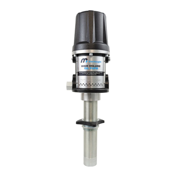
Heavy Duty Oil Pump
Instruction Manual
HVOP3 & HVOP5
WARNING:
Read carefully and understand all INSTRUCTIONS before operating. Failure to follow the safety
rules and other basic safety precautions may result in serious personal injury.
Save these instructions in a safe place and on hand so that they can be read when required.
Keep these instructions to assist in future servicing.
REV 07/04/23
Advertisement
Table of Contents

Related Manuals for Macnaught HVOP3


Summary of Contents for Macnaught HVOP3
- Page 1 Heavy Duty Oil Pump Instruction Manual HVOP3 & HVOP5 WARNING: Read carefully and understand all INSTRUCTIONS before operating. Failure to follow the safety rules and other basic safety precautions may result in serious personal injury. Save these instructions in a safe place and on hand so that they can be read when required.
-
Page 2: General Safety Regulations
GENERAL SAFETY REGULATIONS WARNING: The warnings, cautions, and instructions discussed in this instruction manual cannot cover all possible conditions or situations that could occur. It must be understood by the operator that common sense and caution are factors that cannot be built into this product, but must be supplied by the operator. -
Page 3: Technical Details
TECHNICAL DETAILS Pneumatic Oil Pumps Technical Data: Item No. HVOP3 HVOP5 Drum Application Stub pump Stub pump Pressure Ratio Air Inlet Pressure 43-175psi 43-175psi Max. Fluid Pressure 520psi 870psi Air Motor Effective Diameter 3" 3" Air Consumption (Per Minute) 7.6CFM @115psi 8.6CFM @115psi... - Page 4 • Follow the Pressure Relief Procedure if the dispensing valve clogs before you clean, check or service the equipment. • Tighten all fluid connections before operating the equipment. • Check the hoses, tubes, and couplings daily. Replace worn or damaged parts immediately. •...
-
Page 5: Installation
INSTALLATION Standard installation 1: cut-off valve 2: Filter 3: Regulator 4: Lubricator 5: Control valve 6: Locking adapter 7: Hose reel Fig.3: Oil supply system installation The above installation is not the integrated oil supply system, just contact the manufacture or distributor if you need. -
Page 6: Troubleshooting
WARNING: Each device with different max working pressure. To reduce the risk of exceed pressure. Make sure the max work pressure for each device. Rated pressure in the system can not exceed the max pressure of any device. Or there will be burst, explosion, malfunction, serious damage. -
Page 7: Limited Warranty
LIMITED WARRANTY 1. The manufacturer warrantees this product against defects in material and craftsmanship, for a period of 36 months from date of purchase, but not including wearing parts. 2. Manufacturer’s liability is limited to replacement or repair of defective material within the warranty period, when returned freight prepaid to the distributor or their designated service depot. - Page 8 EXPLODED AND PARTS LIST FOR HVOP3 SERIES 16 17...
- Page 9 Part No. Description Part No. Description Fixed Block Cover Plate O-ring O-ring Quick Connector Pump Body Pump Body Screw Bracket Sealing Screw Silencer Oil inlet Steel Wire Lock nut Hex Flange Bolt Silencer Component Shock Pad Lip Seal O-ring Shaft Piston rod Compression Spring Shaft...
- Page 10 EXPLODED AND PARTS LIST FOR HVOP5 SERIES 16 17...
- Page 11 Part No. Description Part No. Description O-ring Cover Plate O-ring Fixed Block O-ring Pump Body Quick Connector Bracket Pump Body Sealing Screw Screw Silencer Steel Wire Lock nut Oil inlet Hex Flange Bolt Shock Pad Silencer Component Lip Seal Shaft Piston rod Compression Spring Shaft...
- Page 12 4. Cnnect the rigid suction 8 to the end of the flexible suction tube 6 using the elastic clamp provided. 5. Put the bung adapter 7 into the drum hole. 6. Put the rigid suction tube 8 into the pump and secure it in place. Macnaught Americas (813) 628-5506 | info@macnaughtusa.com * Read Manual Before Use! Size: 145x210mm 157克双铜...
Need help?
Do you have a question about the HVOP3 and is the answer not in the manual?
Questions and answers