Table of Contents
Advertisement
Quick Links
www.proform.com
USERʼS MANUAL
Model No. PFTL05099.0
Serial No.
Write the serial number in the space
above for reference.
Serial Number
Decal
QUESTIONS?
If you have questions, or if parts are
damaged or missing, DO NOT CON-
TACT THE STORE; please contact
Customer Care.
IMPORTANT: Please register this
product (see the limited warranty
on the back cover of this manual)
before contacting Customer Care.
1-888-533-1333
CALL TOLL-FREE:
Mon.–Fri. 6 a.m.–6 p.m. MT
Sat. 8 a.m.–4 p.m. MT
ON THE WEB:
www.proformservice.com
CAUTION
Read all precautions and instruc-
tions in this manual before using
this equipment. Save this manual
for future reference.
Get other manuals https://www.bkmanuals.com
Advertisement
Table of Contents

Related Manuals for Pro-Form PFTL05099.0


Summary of Contents for Pro-Form PFTL05099.0
- Page 1 USERʼS MANUAL Model No. PFTL05099.0 Serial No. Write the serial number in the space above for reference. Serial Number Decal QUESTIONS? If you have questions, or if parts are damaged or missing, DO NOT CON- TACT THE STORE; please contact Customer Care.
-
Page 2: Table Of Contents
TABLE OF CONTENTS WARNING DECAL PLACEMENT ............. .2 IMPORTANT PRECAUTIONS . -
Page 3: Important Precautions
IMPORTANT PRECAUTIONS WARNING: To reduce the risk of serious injury, read all important precautions and in- structions in this manual and all warnings on your treadmill before using your treadmill. ICON as- sumes no responsibility for personal injury or property damage sustained by or through the use of this product. - Page 4 20. Do not attempt to move the treadmill until it is treadmill, and before performing the mainte- properly assembled. (See ASSEMBLY on nance and adjustment procedures described in page 6, and HOW TO MOVE THE TREADMILL this manual. Never remove the motor hood un- on page 19.) You must be able to safely lift 45 less instructed to do so by an authorized ser- lbs.
-
Page 5: Before You Begin
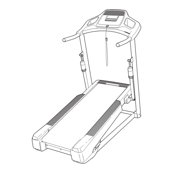
BEFORE YOU BEGIN Thank you for selecting the revolutionary PROFORM ual. To help us assist you, please note the product ® XT 70 treadmill. The XT 70 treadmill offers an impres- model number and serial number before contacting us. sive selection of features designed to make your work- The model number and the location of the serial num- outs at home more enjoyable and effective. -
Page 6: Assembly
ASSEMBLY To hire an authorized service technician to assemble the treadmill, call 1-800-445-2480. Assembly requires two persons. Set the treadmill in a cleared area and remove all packing materials. Do not dispose of the packing materials until assembly is completed. Note: The underside of the treadmill walking belt is coated with high-performance lubricant. - Page 7 1. Make sure that the power cord is unplugged. With the help of a second person, carefully tip the treadmill onto its left side. Have a second person hold the treadmill to prevent it from tipping. Do not pivot the Frame (45). Attach the four Base Feet (67) to the Base (62) in the locations shown with four #8 x 3/4"...
- Page 8 3. Identify the Right Upright Spacer (73), which is marked with an "R." Orient the Right Upright Spacer so that the "R" is in the position shown. Insert the Upright Wire (91) through the Right Upright Spacer (73). Set the Right Upright Hole Bracket Spacer on the Base (62).
- Page 9 5. With the help of a second person, carefully tip the treadmill onto its right side. Have a second person hold the treadmill to prevent it from tipping. Do not pivot the Frame (45). Attach a Wheel (66) to the Base (62) with a 3/8" x 1 1/2"...
- Page 10 7. Hold the Right Handrail (88) near the Right Upright (72). Insert the Upright Wire (91) through the large hole on the bottom of the Right Handrail. Pull the Upright Wire out of the hole in the side of the Right Handrail. Set the Right Handrail (88) and the Left Handrail (87) on the Right and Left Uprights (72, 64).
- Page 11 9. Set the console assembly on the Left and Right Handrails (87, 88). Be careful not to pinch any Console wires. Insert the excess Upright Wire (91) into Assembly the Right Handrail, and insert the Console Ground Wire (80) into the console assembly. Attach the console assembly to the Handrails (87, 88) with five #8 x 3/4"...
- Page 12 11. If necessary, press the Left Accessory Tray (81) and the Right Accessory Tray (82) into the con- Console sole assembly. Press the indicated sides of Assembly First the Accessory Trays into the console assem- bly first. First 12. Make sure that all parts are properly tightened before you use the treadmill. If there are sheets of clear plastic on the treadmill decals, remove the plastic.
-
Page 13: Operation And Adjustment
OPERATION AND ADJUSTMENT THE PRE-LUBRICATED WALKING BELT tric shock. This product is equipped with a cord having an equipment-grounding conductor and a grounding plug. Plug the power cord into a surge suppressor, Your treadmill features a walking belt coated with high- performance lubricant. - Page 14 CONSOLE DIAGRAM Clip FEATURES OF THE CONSOLE You can even listen to your favorite workout music or audio books with the consoleʼs stereo sound system. The treadmill console offers an impressive array of To turn on the power, see page 15. To use the man- features designed to make your workouts more effec- ual mode, see page 15.
- Page 15 HOW TO TURN ON THE POWER 3. Adjust the incline level. IMPORTANT: If the treadmill has been exposed to To adjust the incline to the desired level, see page cold temperatures, allow it to warm to room tem- 18. Press the increase and decrease buttons next perature before turning on the power.
- Page 16 7. Select a display mode and monitor your HOW TO USE A PRESET WORKOUT progress with the display. 1. Insert the key into the console. The console offers several display modes. The dis- play mode that you select will determine which See HOW TO TURN ON THE POWER on page 15.
- Page 17 HOW TO USE THE IFIT TRAINING MODE During the workout, the profile will show Current Segment your progress. The The optional iFit Live module allows you to connect flashing segment your treadmill to your wireless network and unlocks ex- of the profile repre- citing new features.
- Page 18 THE INFORMATION MODE HOW TO ADJUST THE INCLINE OF THE TREADMILL The console features an information mode that keeps To vary the intensity of your exercise, you can adjust track of the total distance that the walking belt has the incline of the treadmill. There are two incline levels. Before adjusting the incline, remove the key and moved and the total number of hours that the treadmill unplug the power cord.
-
Page 19: How To Move The Treadmill
HOW TO MOVE THE TREADMILL Before moving the treadmill, remove the key and un- plug the power cord. Console Due to the size and weight of the treadmill, moving it re- quires two people. Hold the uprights firmly near the con- Upright sole. -
Page 20: Troubleshooting
TROUBLESHOOTING Most treadmill problems can be solved by following the simple steps below. Find the symptom that applies, and follow the steps listed. If further assistance is needed, see the front cover of this manual. PROBLEM: The power does not turn on SOLUTION: a. - Page 21 Locate the Reed Switch (33) and the Magnet (39) on the left side of the Pulley (38). Turn the Pulley 1/8 in. until the Magnet is aligned with the Reed Switch. Make sure that the gap between the Magnet and the Reed Switch is about 1/8 in. (3 mm). If necessary, loosen the #8 x 3/4"...
- Page 22 PROBLEM: The walking belt is off-center or slips when walked on SOLUTION: a. If the walking belt is off-center, first remove the key and UNPLUG THE POWER CORD. If the walking belt has shifted to the left, use the hex key to turn the left idler roller bolt clockwise 1/2 of a turn;...
-
Page 23: Exercise Guidelines
EXERCISE GUIDELINES WARNING: Aerobic Exercise—If your goal is to strengthen your cardiovascular system, you must perform aerobic exer- Before beginning this cise, which is activity that requires large amounts of or any exercise program, consult your physi- oxygen for prolonged periods of time. For aerobic ex- cian. -
Page 24: Part List
PART LIST—Model No. PFTL05099.0 R0210A To locate the parts listed below, see the EXPLODED DRAWING near the end of this manual. Key No. Qty. Description Key No. Qty. Description 3/8" x 4" Bolt Bottom Incline Assembly Bracket 3/8" x 2 1/4" Patch Bolt Incline Assembly Cover 3/8"... -
Page 25: Exploded Drawing
EXPLODED DRAWING A—Model No. PFTL05099.0 R0210A Get other manuals https://www.bkmanuals.com... - Page 26 EXPLODED DRAWING B—Model No. PFTL05099.0 R0210A Get other manuals https://www.bkmanuals.com...
- Page 27 EXPLODED DRAWING C—Model No. PFTL05099.0 R0210A Get other manuals https://www.bkmanuals.com...
-
Page 28: Ordering Replacement Parts
ORDERING REPLACEMENT PARTS To order replacement parts, please see the front cover of this manual. To help us assist you, be prepared to pro- vide the following information when contacting us: • the model number and serial number of the product (see the front cover of this manual) •...
Need help?
Do you have a question about the PFTL05099.0 and is the answer not in the manual?
Questions and answers