Table of Contents
Advertisement
Quick Links
This manual contains information necessary for the safe and proper use of the BFS-i04 bearingless fan.
Included are specifications for the standard configurations and instructions regarding its use, installation,
operation, adjustment, inspection, and maintenance. For special configurations refer to accompanying
information. Please familiarize yourself with the contents of this manual to ensure the safe and effective use
of this product. After reading this manual, please store it where the personnel responsible for operating the
bearingless fan can readily refer to it at any time.
®
The Levitronix
Service Software (with according manual Levitronix
operation, troubleshooting, parameter logging or user specific configurations. For the bearingless fan the
®
Levitronix
Service Software version V2.0.9.6 or higher is needed.
PL-3507-00, Rev00, DCO# 23-128
Bearingless Fan BFS-i04
870 Pa
3
4.4 m
/min
USER MANUAL
(3.5 inH
O)
2
(155 cfm)
Doc.# PL-4048-00) is available for
User Manual for BFS-i04
www.levitronix.com
First Release: 30-Nov-2022
Last Update: 26-Jun-2023
Advertisement
Table of Contents

Subscribe to Our Youtube Channel
Related Manuals for Levitronix BFS-i04


Summary of Contents for Levitronix BFS-i04
- Page 1 (155 cfm) USER MANUAL This manual contains information necessary for the safe and proper use of the BFS-i04 bearingless fan. Included are specifications for the standard configurations and instructions regarding its use, installation, operation, adjustment, inspection, and maintenance. For special configurations refer to accompanying information.
-
Page 2: Table Of Contents
User Manual for BFS-i04 www.levitronix.com Table of Contents SAFETY PRECAUTIONS ......................3 SPECIFICATIONS ........................4 Specification of Components ......................4 System Configuration ........................6 2.2.1 Standard System Configuration ........................6 2.2.2 System Configuration ATEX / IECEx ......................6 Basic Dimensions of Main Components .................... 7 General Environmental Conditions .................... -
Page 3: Safety Precautions
1 Safety Precautions The BFS-i04 bearingless fan is designed to be used in industrial production machines and equipment containing ventilation circuits. Typical applications are semiconductor and chemical manufacturing equipment. Installation shall be done by qualified personnel only. The following safety precautions and all “CAUTION”, “WARNING”... -
Page 4: Specifications
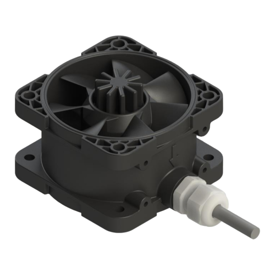
User Manual for BFS-i04 www.levitronix.com 2 Specifications 2.1 Specification of Components Figure 1: Standard fan Figure 2: Accessories PL-3507-00, Rev00, DCO# 23-128... - Page 5 Interface Panel FIP-1.1 100-91638 - 1 x Circular COM for LUI-B.1 or USB-RS485 adaptor Easy wiring of power and PLC signals for up to four BFS-i04 fans, see Purpose section 4.3 for further information Specifications Firmware A8.00, IP65, 5 to 24 V supply voltage User Panel LUI-B.1-06...
-
Page 6: System Configuration
User Manual for BFS-i04 www.levitronix.com 2.2 System Configuration 2.2.1 Standard System Configuration AC/DC Power Supply Flow or Pressure Sensor (optional, not included) Tubing Gasket (not included) User Panel Adaptor Cable Cable Impeller Integrated Bushing Mounting Motor and Flange Electronics Motor Cable... -
Page 7: Basic Dimensions Of Main Components
, PVC Signal: 6 x 0.14 mm , PVC Figure 5: Basic dimensions in mm [in] of bearingless fan BFS-i04.1 Note: Non-tolerated dimensions are for reference only, dimensions in inch are rounded only Figure 6: Basic dimensions of adaptor cable ICH-5.1-03... -
Page 8: General Environmental Conditions
User Manual for BFS-i04 www.levitronix.com Figure 7: Basic dimensions of interface panel FIP-1.1 Figure 8: Basic dimensions of user panel LUI-B.1 2.4 General Environmental Conditions Condition Limits Usage Indoor Altitude Up to 2000 m Operating ambient temperature 0 to 40°C Storage ambient temperature -20 to 80°C... -
Page 9: Pressure-Flow Curves
-1000 -4.0 Flow / m /min Figure 9: Pressure-flow curves of bearingless fan BFS-i04.1 Note: Typical values measured for BFS-i04.1 • , Q = Flow [l/s], P = Pressure Drop [Pa]). Pressure Drop Coefficient at 0 rpm: C = 0.506 (P = C x Q... -
Page 10: Engineering Information
Rotational Speed / rpm Figure 11: Peak power consumption during acceleration (DC input) Note 1: Typical values measured for BFS-i04.1 at operating point with maximum power consumption Note 2: Dashed line: example of optional input power limitation PL-3507-00, Rev00, DCO# 23-128... -
Page 11: Power Supply
Traco Power TSP 180-124 3.1.3 Inrush Current The BFS-i04 features an e-fuse limiting the inrush current. A peak value of 0.34 A with an I t value of 0.006 A s was measured by hot-plugging the BFS-i04 with 5 m cable length to a 180 W power supply. -
Page 12: Sound Pressure Level
3.2 Sound Pressure Level The sound pressure level emitted by the BFS-i04 depends strongly on the installation, operating point, and rotational speed. It is recommended that customers measure the sound pressure level after installation of the fan in their setup during typical operation. -
Page 13: Installation
RS485 Fieldbus Multi-System Arrays: Several systems can be directly connected to the same RS485 master. See Figure 13. ® Address setting of the fan units can be done with the Levitronix Service Software and a PC. A termination resistor is recommended for long bus lengths. Do not use closed ring arrangements. - Page 14 Reference level to all analog / digital signals Table 5: Standard configuration of motor connector ® Note: Levels and assignments of analog and digital inputs and outputs are configurable in EEPROM editor of Levitronix Service Software or through Modbus protocol. See firmware specification (SW-3506-00) for detailed information YN-485I-TR ICS-1.2...
-
Page 15: Electrical Schematics Overview Of Motor Interface
User Manual for BFS-i04 www.levitronix.com 4.1.2 Electrical Schematics Overview of Motor Interface Bearingless fan Pin numbers, wire colors Example of user interface circuit and wire name interface circuit B3 / Blue: Digital input Max. pin voltage digital 27 kW 100 kW 5..24 V... -
Page 16: Mechanical Installation
Only remove rotor if necessary. Keep distance to pacemakers and handle fan rotor with care. WARNING Only specific BFS-i04 bearingless fans are classified for the use in Ex classified locations. Refer to the corresponding section in the manual. WARNING... -
Page 17: Mounting Proposals
4.2.2 Mounting Proposals BFS-i04 fans can be adapted into many different duct systems and may be operated in parallel or series to achieve higher flow or pressure. This section shows a few of many possible mounting scenarios. For more in- ®... -
Page 18: Installation Examples With Interface Panel
The interface panel FIP-1.1 can be used for easy wiring of up to four fans. The panel can be mounted to a DIN ® rail. Figure 18 describes two of many possible scenarios. For more in-depth information contact Levitronix technical support (section 6.3). See section 3.1.2 for the selection of the power supply. -
Page 19: Operation
Do not touch the fan rotor while it is moving. Please consider the following notes for safe and successful operation of the bearingless fan BFS-i04 to prevent injury to personnel or damage to equipment: •... -
Page 20: Troubleshooting And Support
The Service Software can be used to operate the system, for troubleshooting, parameter logging and user specific system configuration. For usage of the Service Software contact the technical support (below). 6.3 Technical Support For troubleshooting, support, and detailed technical information contact Levitronix Technical Service Department: ... -
Page 21: Appendix
7 Appendix 7.1 Regulatory Status 7.1.1 CE / UKCA Marking We herewith declare that the bearingless fan BFS-i04, in its various configurations, is in conformity with the below mentioned European Directives and UK Statutory Instruments. Machinery Directive 2006/42/EU / SI 2008/1597: The machinery directive essentially has been followed by a risk analysis, according to mitigation actions and a user manual for safe operation. -
Page 22: Symbols And Signal Words
User Manual for BFS-i04 www.levitronix.com 7.2 Symbols and Signal Words Symbol / Description Type Source Signal Word Indication of an imminently hazardous situation that, if not DANGER avoided, will result in death or severe injury. Limited to the Signal word SEMI S1-0701 most extreme situation.
Need help?
Do you have a question about the BFS-i04 and is the answer not in the manual?
Questions and answers