Table of Contents
Advertisement
Quick Links
This manual contains information necessary for the safe and proper use of the BFS-i10 bearingless fan.
Included are specifications for the standard configurations and instructions regarding its use, installation,
operation, adjustment, inspection, and maintenance. For special configurations refer to accompanying
information. Please familiarize yourself with the contents of this manual to ensure the safe and effective
use of this product. After reading this manual, please store it where the personnel responsible for operating
the bearingless fan can readily refer to it at any time.
®
The Levitronix
Service Software (with according manual Levitronix
operation, troubleshooting, parameter logging or user specific configurations. For the bearingless fan the
®
Levitronix
Service Software version V2.0.8.0 or higher is needed.
PL-3505-00, Rev00, DCO# 21-249
Bearingless Fan BFS-i10
1150 Pa
3
40 m
/min
Max. Speed: 7400 rpm
USER MANUAL
(4.6 inH
O)
2
(1413 cfm)
Doc.# PL-4048-00) is available for
User Manual for BFS-i10
www.levitronix.com
First Release: 19-Jan-2021
Last Update: 03-Nov-2021
Advertisement
Table of Contents

Subscribe to Our Youtube Channel
Related Manuals for Levitronix BFS-i10


Summary of Contents for Levitronix BFS-i10
- Page 1 Max. Speed: 7400 rpm USER MANUAL This manual contains information necessary for the safe and proper use of the BFS-i10 bearingless fan. Included are specifications for the standard configurations and instructions regarding its use, installation, operation, adjustment, inspection, and maintenance. For special configurations refer to accompanying information.
-
Page 2: Table Of Contents
User Manual for BFS-i10 www.levitronix.com Table of Contents SAFETY PRECAUTIONS ......................3 SPECIFICATIONS ........................4 Specification of Components ......................4 General Environmental Conditions ....................5 System Configuration ........................6 2.3.1 Standard System Configuration ........................6 2.3.2 System Configuration ATEX / IECEx ......................6 Basic Dimensions of Main Components .................... -
Page 3: Safety Precautions
1 Safety Precautions The BFS-i10 bearingless fan is designed to be used in industrial production machines and equipment containing ventilation circuits. Typical applications are semiconductor and chemical manufacturing equipment. Installation shall be done by qualified personnel only. Following safety precautions and all “CAUTION”, “WARNING”... -
Page 4: Specifications
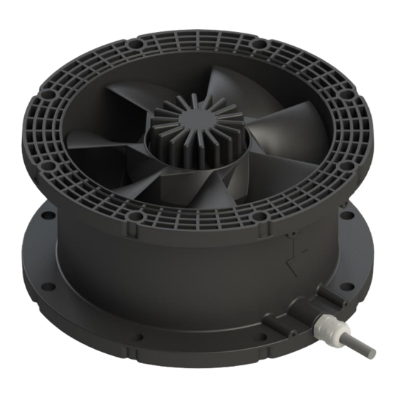
User Manual for BFS-i10 www.levitronix.com 2 Specifications 2.1 Specification of Components Figure 1: Standard fan Figure 2: Standard accessories PL-3505-00, Rev00, DCO# 21-249... -
Page 5: General Environmental Conditions
User Manual for BFS-i10 www.levitronix.com Pos. Component Article Name Article # Characteristics Value / Feature Voltage, Power Input 48 V DC ±10%, 900 W (Option: 24 V DC ±5%, 150 W, with reduced max. speed of 4000 rpm.) Max. Pressure, Max. Flow 1150 Pa (4.6 inH... -
Page 6: System Configuration
User Manual for BFS-i10 www.levitronix.com 2.3 System Configuration • Operation and Interfaces: System control is possible through analog and digital inputs or via the RS485 interface. The latter can be used as a fieldbus or with an RS485 to USB converter from a PC via the Levitronix ®... -
Page 7: Basic Dimensions Of Main Components
PP, electrically conductive, (PLC, RS485): flame retardant 0.14 mm , PVC Connector Signal: TE D1200 1-1827864-6 Figure 5: Basic dimensions in mm of bearingless fan BFS-i10.1 Figure 6: Basic dimensions of cable adapters ICP-6.1-03 and ICS-5.1-03 PL-3505-00, Rev00, DCO# 21-249... -
Page 8: Pressure-Flow Curves
Released Performance Released Performance -1300 -5.2 Flow / m /min Figure 7: Pressure-flow curves of bearingless fan BFS-i10.1 Typical values measured for BFS-i10.1 • Pressure Drop Coefficient at 0 rpm: C = 0.0085 P = C x Q , Q = Flow [l/s], P = Pressure Drop [Pa]). -
Page 9: Engineering Information
7500 Rotational Speed / rpm Figure 9: Peak power consumption during acceleration (DC input) Typical values measured for BFS-i10.1 at operating point with maximum power consumption Dashed line: example of optional input power limitation • Steady State Power Consumption: Depends on the actual speed, pressure, and flow. Figure 8 visualizes the steady state power consumption for different operating points. -
Page 10: Power Supply
® with according speed and/or input power limitations. Please note that only the general functionality of the BFS-i10 in combination with the given supplies was tested, and no recommendations in terms of reliability, efficiency, certifications, cost effectiveness or similar are given. -
Page 11: Fan Mounting
Note: Dimensions in mm. 3.2.2 Mounting Proposals BFS-i10 fans can be adapted into many different duct systems and may be operated in parallel or series to achieve higher flow or pressure. This section describes a few of many possible mounting scenarios. For more in-depth information contact Levitronix ®... -
Page 12: Sound Pressure Level
Figure 12: Examples of mounting with through holes (left) and self-cutting thread inserts (right) 3.3 Sound Pressure Level The sound pressure level emitted by the BFS-i10 depends strongly on the installation, operating point, and rotational speed. It is recommended that customers measure the sound pressure level after installation of the fan in their setup during typical operation. -
Page 13: Installation
If other power supplies are used ® than the ones tested by Levitronix , it is highly recommended to test these under dynamic conditions (acceleration and deceleration of the fan up to maximum rotational speed). - Page 14 RS485 Fieldbus Multi-System Arrays: Several systems can be directly connected to the same RS485 master. Following points and information shall be considered: a. Address setting of the fan units can be done with the Levitronix ® Service Software and a PC.
-
Page 15: Electrical Schematics Overview Of Motor Interface
User Manual for BFS-i10 www.levitronix.com 4.1.3 Electrical Schematics Overview of Motor Interface Bearingless fan Pin numbers, wire colors Example of user interface circuit and wire name interface circuit B4 / Pink: Digital input 1 2.2 kW B5 / Gray: Digital input 2 5..24 V... -
Page 16: Mechanical Installation
Only remove rotor if necessary. Keep distance to pacemakers and handle fan rotor with care. WARNING Only specific BFS-i10 bearingless fans are classified for the use in Ex classified locations. Refer to the corresponding section in the manual. WARNING... -
Page 17: Operation
Do not touch the fan rotor while it is moving. Please consider the following notes for safe and successful operation of the bearingless fan BFS-i10 to prevent injury to personnel or damage to equipment: •... -
Page 18: Troubleshooting And Support
The integrated PLC provides status and error signals. However, the source of error cannot be identified by these signals. For detailed analysis and debugging it is recommended to use the Levitronix Service Software (see below). Alternatively, the Status, Error, Warning and Message bytes can be read using Modbus ®... -
Page 19: Appendix
7 Appendix 7.1 Regulatory Status 7.1.1 CE Marking We herewith declare that the bearingless fan BFS-i10, in its various configurations, is in conformity with the below mentioned European Directives. Machinery Directive 2006/42/EC: The machinery directive essentially has been followed by a risk analysis, according mitigation actions and a user manual for safe operation. -
Page 20: Symbols And Signal Words
User Manual for BFS-i10 www.levitronix.com 7.2 Symbols and Signal Words Symbol / Description Type Source Signal Word Indication of an imminently hazardous situation that, if not DANGER avoided, will result in death or severe injury. Limited to the Signal word SEMI S1-0701 most extreme situation.
Need help?
Do you have a question about the BFS-i10 and is the answer not in the manual?
Questions and answers