Table of Contents
Advertisement
Quick Links
INSTALLER: Leave this manual with party responsible for use and operation.
OWNER: Retain this manual for future reference.
NOTICE: DO NOT discard this manual!
Models:
MDV3732
This appliance may be installed as an OEM
installation in manufactured home (USA
only) or mobile home and must be installed
in accordance with the manufacturer's
instructions and the Manufactured Home
Construction and Safety Standard, Title 24
CFR, Part 3280 in the United States, or the
Standard for Installation in Mobile Homes,
CAN/CSA Z240 MH Series, in Canada.
This appliance is only for use with the type(s)
of gas indicated on the rating plate. This
appliance is not convertible for use with other
gases, unless a certifi ed kit is used.
Installation Manual
Installation and Appliance Setup
Heatilator • MDV3732 Installation Manual • 2386-980 Rev. D • 11/16
WARNING:
FIRE OR EXPLOSION HAZARD
Failure to follow safety warnings exactly
could result in serious injury, death, or
property damage.
• DO NOT store or use gasoline or other fl am-
mable vapors and liquids in the vicinity of this
or any other appliance.
• What to do if you smell gas
- DO NOT try to light any appliance.
- DO NOT touch any electrical switch. DO
NOT use any phone in your building.
- Leave the building immediately.
- Immediately call your gas supplier from
a neighbor's phone. Follow the gas sup-
plier's instructions.
- If you cannot reach your gas supplier, call
the fi re department.
• Installation and service must be performed
by a qualifi ed installer, service agency, or the
gas supplier.
DANGER
DO NOT TOUCH GLASS
NEVER ALLOW CHILDREN
TO TOUCH GLASS.
A barrier designed to reduce the risk of
burns from the hot viewing glass is provided
with this appliance and shall be installed for
the protection of children and other at-risk
individuals.
In the Commonwealth of Massachusetts installation must be
performed by a licensed plumber or gas fi tter.
See Table of Contents for location of additional Commonwealth
of Massachusetts requirements.
HOT GLASS WILL
CAUSE BURNS.
UNTIL COOLED.
1
Advertisement
Table of Contents

Subscribe to Our Youtube Channel
Related Manuals for Hearth & Home MDV3732


Summary of Contents for Hearth & Home MDV3732
- Page 1 fi tter. appliance is not convertible for use with other See Table of Contents for location of additional Commonwealth gases, unless a certifi ed kit is used. of Massachusetts requirements. Heatilator • MDV3732 Installation Manual • 2386-980 Rev. D • 11/16...
-
Page 2: Table Of Contents
A. Vent Collar Preparation ......30 B. Securing and Leveling the Appliance ....32 = Contains updated information. Heatilator • MDV3732 Installation Manual • 2386-980 Rev. D • 11/16... -
Page 3: Installation Standard Work Checklist
Comments: Further description of the issues, who is responsible (Installer/ Builder/ Other Trades, etc) and corrective action needed _____________________________________________________________________________________ _________________________________________________________________________________________________ _________________________________________________________________________________________________ Comments Communicated to party responsible ____________________ by ______________________on ___________ (Builder / Gen. Contractor/) (Installer) (Date) = Contains updated information. 2386-982 4/15 Heatilator • MDV3732 Installation Manual • 2386-980 Rev. D • 11/16... -
Page 4: Product Specifi C And Important Safety Information
• A 110-120 VAC circuit for this product must be protected with ground-fault circuit-interrupter protection, in compliance with the applicable electrical codes, when it is installed in locations such as in bathrooms or near sinks. Heatilator • MDV3732 Installation Manual • 2386-980 Rev. D • 11/16... -
Page 5: Requirements For The Commonwealth Of Massachusetts
VENT DIRECTLY BELOW. KEEP CLEAR OF ALL OB- of the installation. STRUCTIONS”. See Gas Connection section for additional Common- wealth of Massachusetts requirements. Heatilator • MDV3732 Installation Manual • 2386-980 Rev. D • 11/16... -
Page 6: Getting Started
Non-corrosive leak check solution venting for any transportation needs. 1/2 - 3/4 in. length, #6 or #8 Self-drilling screws Caulking material (300ºF minimum continuous exposure rating) Heatilator • MDV3732 Installation Manual • 2386-980 Rev. D • 11/16... -
Page 7: Framing And Clearances
Ø ELECTRICAL ACCESS Location Inches Millimeters Location Inches Millimeters 16-5/16 31-1/8 29-7/16 25-3/4 12-7/8 34-5/16 15-7/8 6-5/8 6-7/8 2-3/8 2-3/16 36-1/4 1-1/16 8-13/16 23-3/8 Figure 3.1 Appliance Dimensions Heatilator • MDV3732 Installation Manual • 2386-980 Rev. D • 11/16... - Page 8 See Section 10 for facing and fi nishing detail. SRV2355-021 DECORATIVE FRONT 29-1/2 25-7/8 30-15/16 2-3/16 1-1/2 27-1/4 28-3-/4 SRV2355-021 Figure 3.2 Decorative Front Dimensions - SRV2355-021 Heatilator • MDV3732 Installation Manual • 2386-980 Rev. D • 11/16...
-
Page 9: Clearances To Combustibles
E Min. F Min. 59-1/2 62-1/4 16-1/4 48-1/2 68-3/4 15-1/16 7-1/2 7-1/8 See Section 5.D for MDV3732 Alcove Installation 1067 1511 1117 1581 1232 1746 Figure 3.3 Appliance Locations Heatilator • MDV3732 Installation Manual • 2386-980 Rev. D • 11/16... -
Page 10: Constructing The Appliance Chase
16-1/4 16-1/4 MDV3732 * Adjust framing dimensions for interior sheathing (such as sheetrock) C** Add 12 inches for rear venting with one 90º elbow. Figure 3.4 Clearances to Combustibles Heatilator • MDV3732 Installation Manual • 2386-980 Rev. D • 11/16... -
Page 11: Termination Location And Vent Information
Over 16/12 to 18/12 ..........7.0 Over 18/12 to 20/12 ..........7.5 Over 20/12 to 21/12 ..........8.0 * 3 foot minimum in snow regions Figure 4.1 Minimum Height From Roof To Lowest Discharge Opening Heatilator • MDV3732 Installation Manual • 2386-980 Rev. D • 11/16... -
Page 12: Chimney Diagram
Figure 4.3 Minimum Clearances for Termination • Vinyl protection kits are suggested for use with vinyl siding. Heatilator • MDV3732 Installation Manual • 2386-980 Rev. D • 11/16... -
Page 13: Approved Pipe
WARNING! Risk of Fire or Asphyxiation. This appli- ance requires a separate vent. DO NOT vent to a pipe serving a separate solid fuel burning appliance. Heatilator • MDV3732 Installation Manual • 2386-980 Rev. D • 11/16... -
Page 14: Use Of Elbows
DVP6 4-1/4 DVP12 8-1/2 DVP24 DVP36 25-1/2 DVP48 1219 DVP6A 3 to 6 76 to 152 2-1/8-4-1/4 54-108 DVP12A 3 to 12 76 to 305 2-1/8-8-1/2 54-216 Figure 4.4 Heatilator • MDV3732 Installation Manual • 2386-980 Rev. D • 11/16... -
Page 15: Measuring Standards
However, 1 in. the vent attachment point and the fi restop CLEARANCE location are considered to be supports. Figure 4.6 Heatilator • MDV3732 Installation Manual • 2386-980 Rev. D • 11/16... -
Page 16: Vent Diagrams
Note: There MUST be a 25% reduction in total H when using fl ex vent except when using the simple up and out installation (see Figure 4.6). Figure 4.7 Heatilator • MDV3732 Installation Manual • 2386-980 Rev. D • 11/16... - Page 17 • When using SLP-HRC-SS and SLP-HRC-ZC-SS termination caps on top vented fi replaces, a two foot minimum vertical vent section is required before installing fi rst elbow. INSTALLED HORIZONTALLY Figure 4.8 Heatilator • MDV3732 Installation Manual • 2386-980 Rev. D • 11/16...
- Page 18 • When using SLP-HRC-SS and SLP-HRC-ZC- SS termination caps on top vented fi replaces, a two foot minimum vertical vent section is required before installing fi rst elbow. Figure 4.9 Heatilator • MDV3732 Installation Manual • 2386-980 Rev. D • 11/16...
- Page 19 fl ame height. If the vent confi guration has Figure 4.11 a total vertical of 15-60 feet, an exhaust restrictor may be needed. The exhaust restrictor can be located in the appliance manual bag. Heatilator • MDV3732 Installation Manual • 2386-980 Rev. D • 11/16...
- Page 20 Note: There MUST be a 25% reduction HORIZONTALLY in total H when using fl ex vent except when using the simple up and out installation (see Figure 4.6). Figure 4.13 Heatilator • MDV3732 Installation Manual • 2386-980 Rev. D • 11/16...
- Page 21 Note: There MUST be a 25% reduction in total H when using fl ex vent except when using the simple up and out installation (see Figure 4.6). Figure 4.14 Heatilator • MDV3732 Installation Manual • 2386-980 Rev. D • 11/16...
- Page 22 = 24 in. Max. (610 mm) Note: Use DVP Series components only. Figure 4.15 = 9 in. (229 mm) Maximum One 45º Elbow Note: Use DVP Series components only. Figure 4.16 Heatilator • MDV3732 Installation Manual • 2386-980 Rev. D • 11/16...
- Page 23 914 mm 6 ft. 1.8 m 13-1/2 ft. 4.1 m MAX. = 7-1/2 ft. (2.3 m) MAX. = 13-1/2 ft. (4.1 m) MAX. = 40 ft. (12.2 m) Figure 4.18 Heatilator • MDV3732 Installation Manual • 2386-980 Rev. D • 11/16...
- Page 24 914 mm Note: Use DVP Series H MAX. = 6-1/2 ft. (2 m) components only. V + H+ H MAX. = 40 ft. (12.2 m) INSTALLED HORIZONTALLY Figure 4.20 Heatilator • MDV3732 Installation Manual • 2386-980 Rev. D • 11/16...
- Page 25 14-1/2 ft. 4.4 m MAX. = 7-1/2 ft. (2.3 m) MAX. = 14-1/2 ft. (4.4 m) MAX. = 40 ft. (12.2 m) Note: Use DVP Series components only. Figure 4.21 Heatilator • MDV3732 Installation Manual • 2386-980 Rev. D • 11/16...
- Page 26 CAUTION! DO NOT use any fl ue restrictor when vent- ing with the DV-46DVA-GCL adapter and LINK-DV30B kit. This could result in poor fl ame appearance, sooting, pilot malfunction, or overheating. Heatilator • MDV3732 Installation Manual • 2386-980 Rev. D • 11/16...
- Page 27 10 ft. 3.05 m 0 ft. 0 mm Minimum 10 ft. 3.05 m Maximum 40 ft. 12.2 m 2 ft. 610 mm Maximum 40 ft. 12.2 m Figure 4.24 Heatilator • MDV3732 Installation Manual • 2386-980 Rev. D • 11/16...
-
Page 28: Vent Clearances And Framing
* Shows center of vent framing hole for top or rear venting. The center of the hole is one (1) in. (25.4 mm) above the center of the horizontal vent pipe. Figure 5.2 Wall Penetration Heatilator • MDV3732 Installation Manual • 2386-980 Rev. D • 11/16... -
Page 29: Ceiling Firestop/Floor Penetration Framing
INSTALL ATTIC INSULATION SHIELDS BEFORE OR AFTER INSTALLATION OF VENT SYSTEM CEILING FIRESTOP CEILING FIRESTOP INSTALLED BELOW CEILING INSTALLED ABOVE CEILING Figure 5.4 Installing the Attic Shield Heatilator • MDV3732 Installation Manual • 2386-980 Rev. D • 11/16... -
Page 30: Appliance Preparation
The heat shield must remain in the vertical position. 2 SCREWS Figure 6.3 Replace the two screws as shown. Figure 6.6 Remove the insulation from the outer vent pipe. Heatilator • MDV3732 Installation Manual • 2386-980 Rev. D • 11/16... - Page 31 Use two self- tapping screws to secure gasket to outer wrap. Figure 6.9 Cut the metal retaining band and fold the sides out. Heatilator • MDV3732 Installation Manual • 2386-980 Rev. D • 11/16...
-
Page 32: Securing And Leveling The Appliance
• Secure the appliance to the fl oor by inserting two screws through the pilot holes at the bottom of the appliance. NAILING TABS (BOTH SIDES) Figure 6.13 Proper Positioning, Leveling And Securing Of An Appliance Heatilator • MDV3732 Installation Manual • 2386-980 Rev. D • 11/16... -
Page 33: Venting And Chimneys
fl ue at the horizontal elbow joint to prevent the elbow from rotating. Use screws no longer than 1/2 INCORRECT in. (13 mm). If predrilling screw holes, DO NOT penetrate inner pipe. Figure 7.4 Seams Heatilator • MDV3732 Installation Manual • 2386-980 Rev. D • 11/16... -
Page 34: Assemble Slip Sections
• Only outer pipes are sealed, sealing the inner fl ue is not then rotate counterclockwise to lock required. Figure 7.5 Adding Venting Components • All unit collar, pipe, slip section, elbow and cap outer fl ues shall be sealed. Heatilator • MDV3732 Installation Manual • 2386-980 Rev. D • 11/16... -
Page 35: Secure The Vent Sections
Figure 7.11 Align and Disassemble Vent Sections Figure 7.8 Securing Vertical Pipe Sections FOR MANUFACTURED HOME TRANSPORT 120º • Ensure vent pipe is protected against environmental damage during transport. Figure 7.9 Securing Horizontal Pipe Sections Heatilator • MDV3732 Installation Manual • 2386-980 Rev. D • 11/16... -
Page 36: Vertical Termination Requirements
• Caulk the perimeter of the fl ashing where it contacts the roof surface. See Figure 7.13. • Caulk the overlap seam of any exposed pipe sections that are located above the roof line. Heatilator • MDV3732 Installation Manual • 2386-980 Rev. D • 11/16... -
Page 37: Horizontal Termination Requirements
• Rest the small leg on the extended heat shield on top of the pipe section to properly space it from the pipe section. Figure 7.15 Figure 7.15 Important Notice: Heat shields may not be fi eld constructed. Heatilator • MDV3732 Installation Manual • 2386-980 Rev. D • 11/16... - Page 38 DVP-TRAP1 can adjust 1-1/2 in. (3-1/8 to 4-5/8) DVP-TRAP2 can adjust 4 in. (5-3/8 to 9-3/8) DVP-HPC1 can adjust 2-1/8 in. (4-1/4 to 6-3/8) DVP-HPC2 can adjust 4-1/8 in. (6-3/8 to 10-1/2) Heatilator • MDV3732 Installation Manual • 2386-980 Rev. D • 11/16...
-
Page 39: Electrical Information
110-120 VAC to wall switch. Connector 14/2WG Cover Plate outside firebox Copper ground attached GRN wire to GRN screw with inside box GRN wire Figure 8.1 Junction Box Detail Heatilator • MDV3732 Installation Manual • 2386-980 Rev. D • 11/16... -
Page 40: Wiring Requirements
3 VAC WHITE GROUND TO FIREPLACE PLUG IN CHASSIS WIRES BATTERY PACK (TO BROWN) PLUG IN VALVE Figure 8.2 Intellifi re Ignition Wiring Diagram with Factory-Installed SMART-STAT-II Remote Control Heatilator • MDV3732 Installation Manual • 2386-980 Rev. D • 11/16... - Page 41 #1 - #5 LOCATIONS ON/OFF SWITCH NEUTRAL SIDE ON THE HOT SIDE TRANSFORMER 3 VAC PLUG IN VALVE Figure 8.3 Intermittent Pilot Ignition (IPI) Wiring Diagram Using ON/OFF Switch Heatilator • MDV3732 Installation Manual • 2386-980 Rev. D • 11/16...
-
Page 42: Smart-Stat-Ii Remote Control
Canada. Operation is subject to the following two condi- tions: (1) this device may not cause interference, and (2) this device must accept any interference, including interfer- ence that may cause undesired operation of the device. Heatilator • MDV3732 Installation Manual • 2386-980 Rev. D • 11/16... - Page 43 Placing the switch in the OFF position also functions as a safety “lock out” by turning the system off and rendering the remote receiver inoperative. Heatilator • MDV3732 Installation Manual • 2386-980 Rev. D • 11/16...
- Page 44 6. CLOCK - Indicates the current time in AM/PM. ROOM 7. ROOM - Indicates CURRENT room temperature. TIMER F - Indicates degrees Fahrenheit (ºC indicates degrees Celsius). FLAME Figure 8.6 Transmitter LCD Display Screen Heatilator • MDV3732 Installation Manual • 2386-980 Rev. D • 11/16...
- Page 45 fi replace ON or OFF thermostati- cally. To set the desired room temperature: 1. Press the MODE button to place the transmitter into THERMO mode. THERMO ON or OFF will display. Heatilator • MDV3732 Installation Manual • 2386-980 Rev. D • 11/16...
- Page 46 The LCD will display CP until 5 seconds have elapsed, range for the Auto Shutdown feature to operate. and then the LCD screen will return to its normal state. Heatilator • MDV3732 Installation Manual • 2386-980 Rev. D • 11/16...
- Page 47 Seller will not be responsible rights that vary by state, province or nation. for labor charges and/or damage incurred in installation, repair, replacement or for incidental or consequential damages. Heatilator • MDV3732 Installation Manual • 2386-980 Rev. D • 11/16...
-
Page 48: Fan Wiring And Operation
WARNING! Risk of Shock! Replace damaged wire with type 105º C rated wire. Wire must have high temperature insulation. VARIABLE JUNCTION BOX SPEED SWITCH TEMPERATURE SENSOR SWITCH BLUE Figure 8.8 Fan Wiring Diagram Heatilator • MDV3732 Installation Manual • 2386-980 Rev. D • 11/16... -
Page 49: Gas Information
4500 feet (1370 m). • If substituting for these components, please consult local codes for compliance. Check with your local gas utility to determine proper orifi ce size. Heatilator • MDV3732 Installation Manual • 2386-980 Rev. D • 11/16... -
Page 50: Air Shutter Setting
Adjust air shut- ter for longer vertical runs. NOTICE: If sooting occurs, provide more air by opening the air shutter. Air Shutter Settings Models MDV3732 3/16 in. 1/2 in. Heatilator • MDV3732 Installation Manual • 2386-980 Rev. D • 11/16... -
Page 51: Finishing
MAY BE COMBUSTIBLE - TOP AND SIDES 0 IN. 0 IN. 0 IN. HIGH TEMPERATURE SEALANT (300° F/149° C MIN.) TOP AND SIDE SEAL JOINT Figure 10.1 Non-combustible Facing Diagram Heatilator • MDV3732 Installation Manual • 2386-980 Rev. D • 11/16... -
Page 52: Mantel And Wall Projections
MINIMUM 3 FT. MAXIMUM FIREPLACE OPENING See Dimension B on Appliance Dimension Diagram (Figure 3.1). Figure 10.4 Non-Combustible Mantel Leg or Wall Projections (Acceptable on both sides of opening) Heatilator • MDV3732 Installation Manual • 2386-980 Rev. D • 11/16... -
Page 53: Decorative Front Dimensions For Finishing
SHEETROCK/FINISH WALL MATERIAL UP TO 1/2 IN. THICK MAY BE COMBUSTIBLE - TOP AND SIDES 3-1/2 IN. 1/2 IN. 1/2 IN. = NON-COMBUSTIBLE ZONE Figure 10.6 Non-combustible Facing Diagram Heatilator • MDV3732 Installation Manual • 2386-980 Rev. D • 11/16... -
Page 54: Elevated Hearth Systems
Note 1. Add dimensions to Wall Penetration (Figure 5.2) and Rough Opening Height (Figure 3.4). Note 2. Verify Marble Cut Lengths on site prior to cutting. Note 3. Dimensions assume use of a 3/4 in. Hearth Pad. Heatilator • MDV3732 Installation Manual • 2386-980 Rev. D • 11/16... -
Page 55: Appliance Setup
fi rebox or underneath in the control cavity. latch the four glass assembly latches into the groove on the glass frame. LATCHES (BOTH BOTTOM AND TOP) GLASS ASSEMBLY Figure 11.1 Fixed Glass Assembly Heatilator • MDV3732 Installation Manual • 2386-980 Rev. D • 11/16... -
Page 56: Install The Log Assembly
Log #3 SRV2355-703 (LOGS-3732 and LOGS-DV4236): Locate the bottom hole on Log #3 with the shoulder screw on the right front side of the base pan. See Figure 5. Heatilator • MDV3732 Installation Manual • 2386-980 Rev. D • 11/16... - Page 57 Log #6 SRV2391-711 (LOGS-DV4236): Place the right end of Log #6 on the base pan and the left end onto Logs #1 and #3, so that one limb is touching each log as shown in Figure 8. 2355-910F Heatilator • MDV3732 Installation Manual • 2386-980 Rev. D • 11/16...
-
Page 58: Ember And Lava Rock Placement
The embers provided should be enough burner operation. for 3 to 5 applications. Delayed ignition may occur. LAVA ROCK NO EMBERS IN SHADED AREA Figure 11.4 Figure 11.2 Placement of Embers EMBERS Figure 11.3 Heatilator • MDV3732 Installation Manual • 2386-980 Rev. D • 11/16... -
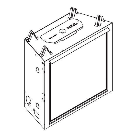
Page 59: Install Decorative Front/Hood
SHIPPING HOOKS (Hook location varies by model) Figure 11.5 Install Decorative Front and Hood Heatilator • MDV3732 Installation Manual • 2386-980 Rev. D • 11/16... -
Page 60: Reference Materials
(254 mm) 14 in. (356 mm) 5 in. 12 in. (127 mm) (305 mm) 6 in. (152 mm) DVP-HVS (Vent Support) DVP-WS (Wall Shield Firestop) Figure 12.1 DVP vent components Heatilator • MDV3732 Installation Manual • 2386-980 Rev. D • 11/16... - Page 61 79 mm 117 mm Length DVP-TRAP 5-3/8 in. 9-3/8 in. Trap2 Horizontal Termination Cap 137 mm 238 mm DVP-TRAP2 DVP-TRAP1 DVP-TRAPK2 DVP-TRAPK1 DVP-HPC1 DVP-HPC2 Figure 12.2 DVP vent components Heatilator • MDV3732 Installation Manual • 2386-980 Rev. D • 11/16...
- Page 62 Cap Shield 13-7/8 in. 9-1/2 in. (352 mm) (241 mm) 26 in. 660 mm 14 in. (356 mm) DVP-HSM-B DRC-RADIUS Extended Heat Shield Cap Shield Figure 12.3 DVP vent components Heatilator • MDV3732 Installation Manual • 2386-980 Rev. D • 11/16...
- Page 63 (356 mm) High Performance Cap 3/8 in. (10 mm) 1 in. (25 mm) 7-3/4 to 10-3/8 in. (197 to 264 mm) DVP-FBHT FireBrickTermination Cap Figure 12.4 DVP vent components Heatilator • MDV3732 Installation Manual • 2386-980 Rev. D • 11/16...
- Page 64 10-1/2 in. (381 mm) 267 mm 10-7/8 in. 276 mm SLP-HRC-SS SLP-HRC-ZC-SS HORIZONTAL TERMINATION CAP DVP-TB1 DVP-TB1 SL-2DVP SLP90 ASSEMBLY DVP-TB1 HORIZONTAL TERMINATION CAP Figure 12.6 SLP Vent Components Heatilator • MDV3732 Installation Manual • 2386-980 Rev. D • 11/16...
- Page 65 8-11/16 in. 1-1/2 in. 12 in. 5-1/2 in. 220 mm 38 mm 305 mm 146 mm SLP-WS SLP-FS Wall Shield Firestop Ceiling Firestop Figure 12.7 SLP Series Vent Components Heatilator • MDV3732 Installation Manual • 2386-980 Rev. D • 11/16...
- Page 66 14-7/16 in. 367 mm 26 in. 660 mm 2-5/16 in. 14-7/16 in. 59 mm 367 mm DVP-HSM-B SLP-WT-BK Extended Heat Shield Wall Thimble-Black Figure 12.8 SLP Series Vent Components Heatilator • MDV3732 Installation Manual • 2386-980 Rev. D • 11/16...
- Page 67 1 in. (25 mm) 13-1/2 in. 343 mm 7-3/4 to 10-3/8 in. (197 to 264 mm) DVP-FBHT SLK-SNKD Horizontal Snorkel Termination Cap Termination Cap Figure 12.9 SLP Series Vent Components Heatilator • MDV3732 Installation Manual • 2386-980 Rev. D • 11/16...
- Page 68 SLP Low Profi le Cap Figure 12.10 SLP Series Vent Components COAXIAL to COLINEAR VENTING LINK-DV30B DVP-2SL DV-46DVA-GCL Flex Liner Kit Adapter Coaxial/Colinear Appliance Connector Figure 12.11 Coaxial to Colinear Vent Components Heatilator • MDV3732 Installation Manual • 2386-980 Rev. D • 11/16...
- Page 69 Use if the PVLP-SLP is installed in a high traffi c 100 FT PV Wire Harness PVI-WH100 area. PVLP-HS PVLP-BEK Heat Shield Brick Kit Figure 12.12 PVLP-SLP Vent Components Heatilator • MDV3732 Installation Manual • 2386-980 Rev. D • 11/16...
-
Page 70: Remote Control, Wall Controls And Wall Switches
Contact Heatilator Consumer Care at 1-800-486-9120 with any questions or concerns. Additional information about your Heatilator fi replace can be found at www.heatilator.com. Printed in U.S.A. - Copyright 2016 Heatilator • MDV3732 Installation Manual • 2386-980 Rev. D • 11/16...
Need help?
Do you have a question about the MDV3732 and is the answer not in the manual?
Questions and answers