
Related Manuals for Toshiba MMW-UP0271LQ-E


Summary of Contents for Toshiba MMW-UP0271LQ-E
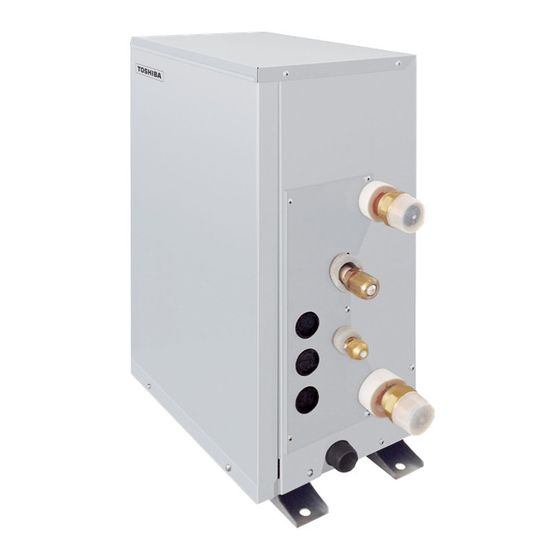
- Page 1 FILE No. A10-2005 AIR CONDITIONER (MULTI TYPE) SERVICE MANUAL Hot Water Module Mid temperature type Model name: MMW-UP0271LQ-E(TR) MMW-UP0561LQ-E(TR) PRINTED IN JAPAN, Dec., 2020, TOMO...
-
Page 2: Table Of Contents
CONTTENTS PRECAUTIONS FOR SAFETY ..................6 1. SUMMARIES OF PRODUCT CHARACTERISTICS ..........11 2. SPECIFICATIONS ....................12 3. WIRING DIAGRAMS ....................13 4. PARTS RATING ...................... 14 5. REFRIGERANT CYCLE DIAGRAM ............... 15 6. CONTROL OUTLINE ....................16 7. COMMUNICATION TYPE, MODEL NAMES AND THE MAXIMUM NUMBER OF CONNECTABLE UNITS .......... - Page 3 (including the hot water modules) made by Toshiba Carrier Corporation or, alternatively, he or she has been instructed in such matters by an individual or individuals who have been trained and is thus thoroughly acquainted with the knowledge related to this work.
- Page 4 Warning Indications on the Air Conditioner Unit [Confirmation of warning label on the main unit] Confirm that labels are indicated on the specified positions If removing the label during parts replace, stick it as the original. WARNING WARNING ELECTRICAL SHOCK HAZARD ELECTRICAL SHOCK HAZARD Disconnect all remote Disconnect all remote electric power supplies before servicing.
- Page 5 Definition of Protective Gear When the air conditioner is to be transported, installed, maintained, repaired or removed, wear protective gloves and ‘safety’ work clothing. In addition to such normal protective gear, wear the protective gear described below when undertaking the special work detailed in the table below.
-
Page 6: Precautions For Safety
PRECAUTIONS FOR SAFETY The manufacturer shall not assume any liability for the damage caused by not observing the description of this manual. DANGER Before carrying out the installation, maintenance, repair or removal work, be sure to set the circuit breaker for both the hot water module and outdoor units to the OFF position. - Page 7 WARNING Before starting to repair the hot water module, read carefully through the Service Manual, and repair the hot water module by following its instructions. Only qualified service person (*1) is allowed to repair the hot water module. Repair of the hot water module by unqualified person may give rise to a fire, electric shocks, injury, water leaks and / or other problems.
- Page 8 When performing repairs using a gas burner, replace the refrigerant with nitrogen gas because the oil that coats the pipes may otherwise burn. When repairing the refrigerating cycle, take the following measures. 1) Be attentive to fire around the cycle. When using a gas stove, etc., be sure to put out fire before work; otherwise the oil mixed with refrigerant gas may catch fire.
- Page 9 Once the repair work has been completed, check for refrigerant leaks, and check the insulation resistance and water drainage. Then perform a trial run to check that the hot water module is running properly. After repair work has finished, check there is no trouble. If check is not executed, a fire, electric shock or injury may be caused.
- Page 10 (*1) Refer to the “Definition of Qualified Installer or Qualified Service Person” Declaration of Conformity Manufacturer: TOSHIBA CARRIER CORPORATION 336 Tadehara, Fuji-shi, Shizuoka-ken 416-8521 JAPAN TCF holder: TOSHIBA CARRIER EUROPE S.A.S Route de Thil 01120 Montluel FRANCE Hereby declares that the machinery described below: Generic Denomination: Hot Water Module...
-
Page 11: Summaries Of Product Characteristics
1. SUMMARIES OF PRODUCT CHARACTERISTICS CONCEPT • To design and produce a mid temperature hot water module, capable of producing up to 50°C outlet water temperature, whilst maximizing the performance and efficiency of the entire VRF system. • To be used in both space heating and domestic hot water applications. Typical applications include hotel, office and residential apartment suits. -
Page 12: Specifications
2. SPECIFICATIONS Model MMW-UP0271LQ-E/TR MMW-UP0561LQ-E/TR Heating capacity *1 (kW) 16.0 Electrical characteristics Power supply *2 1 phase 50Hz 220 – 240V Running current 0.08 0.08 Power consumption Appearance Zinc hot dipping steel plate Dimension Unit Height (mm) Width (leg include) -
Page 13: Wiring Diagrams
3. WIRING DIAGRAMS – 13 –... -
Page 14: Parts Rating
4. PARTS RATING Model MMW- UP0271LQ-E UP0271LQ-TR UP0561LQ-E UP0561LQ-TR Transformer TT-13 Flow switch VK320M, Cap color Blue VK320M, Cap color Black PAM-MD12TF-301 Pulse motor Pulse motor valve PAM-B40YGTF-1 PAM-B60YGTF-1 2 way valve coil FQ-G593, AC220-240V 50/60Hz, Lead wire length 800 mm 2 way valve body FDF2A88 Dia. -
Page 15: Refrigerant Cycle Diagram
5. REFRIGERANT CYCLE DIAGRAM (TC2) Gas side Water Outlet PLATE TYPE HEAT EXCHANGER (TA) Water Inlet Liquid side TCJ2 PULSE (TF) MOTOR VALVE (PMV) Solenoid Capillary Check Temp. Strainer Flow switch valve tube valve sensor – 15 –... -
Page 16: Control Outline
6. CONTROL OUTLINE Item Specification Remarks Upon power 1. Identification of outdoor unit supply reset When the power supply is reset, the outdoor unit is identified, and control is redirected according to the identification result. 2. If power supply reset is performed in the wake of a trouble, the check code is cleared. If the abnormality persists after the Start / Stop button on the remote controller is pushed to resume operation, the check code is redisplayed on the remote controller. - Page 17 Item Specification Remarks Heater control 1. While the heating thermostat ON, the heater relay is output by difference between TG: Satisfaction Ts and TWI, and difference between Ts and TWO, Ts and TG. temperature of discharge Heater ON condition: A and B as shown below Table 1 or Table 2 pressure Heater OFF condition: A or B as shown below Table 1 or Table 2 Table 1...
- Page 18 Item Specification Remarks 10 Defrosting While the outdoor unit is engaged in defrosting control, the hot water modules • Control is performed control perform the following control tasks: per two hours or when the outdoor 1) Close the hot water module PMV to a certain degree and open the SV valve. unit determines its After defrosting control is completed, heating refrigerant (oil) recovery control is need.(It varies...
-
Page 19: Communication Type, Model Names And The Maximum Number Of Connectable Units
7. COMMUNICATION TYPE, MODEL NAMES AND THE MAXIMUM NUMBER OF CONNECTABLE UNITS 7-1. This air conditioning (U series) has new communication specifications, and TU2C- Link (U series) and TCC-Link (other than U series) differ in a communication type. For the communication type and the model names such as each unit or remote controllers, refer to the following table. -
Page 20: Applied Control And Functions
8. APPLIED CONTROL AND FUNCTIONS 8-1. Hot Water Module printed circuit board MCC-1744 – 20 –... -
Page 21: Optional Connector Specifications Of Hot Water Module P.c. Board
8-2. Optional connector specifications of hot water module P.C. board Function Connector No. Pin No. Specification Remarks Start / stop input Start / stop input for HA (J01: In place / Removed = Pulse input (factory default) / Step input) 0 V (COM) —... -
Page 22: Test Operation Of Hot Water Module Unit
8-3. Test operation of hot water module unit Check function for operation of hot water module (Functions at hot water module side) This function is provided to check the operation of the hot water module individually without connecting to the remote controller or the outdoor unit. -
Page 23: Method To Set Hot Water Module Function Dn Code
8-4. Method to set hot water module function DN code (When performing this task, be sure to use a wired remote controller.) Procedure Be sure to stop the air conditioner before making settings <RBC-AMT > Push the buttons simultaneously and hold for at least 4 seconds. - Page 24 Push OFF timer button to confirm the selected indoor unit. Code No. Set data Push the menu button to make Code No. [ ] flash. Change Code No. [ ] with [ ] setting button. Push the menu button to make Set data [ ] flash.
- Page 25 Function CODE No. (DN Code) table (includes all functions needed to perform applied control on site) Item Description At shipment Central control address 0001: No.1 unit 0064: No.64 unit ... TCC-LINK 00Un/0099: 0001: No.1 unit 0128: No.128 unit ... TU2C-LINK Unfixed 00Un: Unfixed (When using U series remote controller) 0099: Unfixed (Other than U series remote controller)
- Page 26 For Central control address (DN [03]), Indoor unit address (DN [13]) Remote controller Communication type Display order ··· ⇔ 0128 ⇔ 00Un ⇔ 0001 ⇔ ··· TU2C-LINK U series ··· ⇔ 0064 ⇔ 00Un ⇔ 0001 ⇔ ··· TCC-LINK ··· ⇔ 0064 ⇔ 0099 ⇔ 0001 ⇔ ··· Other than U series TCC-LINK For Line address (DN [12])
-
Page 27: Applied Control Of Indoor Unit (Including Hot Water Module)
8-5. Applied control of indoor unit (including Hot Water Module) Manual address setting using the remote controller Procedure when setting indoor units’ addresses first under the condition that indoor wiring has been completed and outdoor wiring has not been started (manual setting using the remote controller) Wiring example of 2 refrigerant lines Refrigerant line 1 Refrigerant line 2... - Page 28 <Line (system) address> 12 12 12 12 12 Push the TEMP. buttons repeatedly to set the CODE No. to Push the TIME buttons repeatedly to set a system address. (Match the address with the address on the interface P.C. board of the header outdoor unit in the same refrigerant line.) Push button.
- Page 29 <Indoor unit address> Push the [menu] button until the CODE No. flashes. And using the [ ] buttons, specify the CODE No.13. Push the [menu] button until the SET DATA flashes. And using the [ ] buttons, set an indoor unit address. Push the [OFF timer] button to confirm the SET DATA.
- Page 30 Confirming the indoor unit addresses and the position of an indoor unit using the remote controller Confirming the numbers and positions of indoor units To know the indoor unit addresses though position of the indoor unit is recognized When the unit is individual (the indoor unit is paired with a wired remote controller one-to- one), or it is a group-controlled one.
- Page 31 To find an indoor unit’s position from its address When checking unit numbers controlled as a group <RBC-AMT > (Execute it while the units are stopped.) The indoor unit numbers in a group are indicated one after another. The fan and louvers of the indicated units are activated.
- Page 32 To check all the indoor unit addresses using an arbitrary wired remote controller. (When communication wirings of 2 or more refrigerant lines are interconnected for central control) <RBC-AMT > CODE NO. TEMP. ON / OFF TIMER SET MODE TIME SAVE VENT FILTER RESET...
- Page 33 Changing the indoor unit address using a remote controller To change an indoor unit address using a wired remote controller. The method to change the address of an individual indoor unit (the indoor unit is paired with a wired remote controller one-to-one), or an indoor unit in a group. (The method is available when the addresses have already been set automatically.) <RBC-AMT >...
- Page 34 <RBC-ASCU11 > 3, 4 2, 5 3, 4 3, 4 Push and hold the [menu + ] buttons at same time for more than 10 seconds. Push the [OFF timer] button to confirm the selected indoor unit. Push the [menu] button until the CODE No. flashes. And using the [ ] buttons, specify the CODE No.13.
- Page 35 To change all the indoor unit addresses using an arbitrary wired remote controller. (The method is available when the addresses have already been set automatically.) (When communication wirings of 2 or more refrigerant lines are interconnected for central control) NOTE You can change the addresses of indoor units in each refrigerant line using an arbitrary wired remote controller.
- Page 36 CODE NO. TEMP. ON / OFF TIMER SET MODE TIME SAVE VENT FILTER RESET TEST SWING/FIX UNIT LOUVER Finish 5, 7 Press to finish setting Push the TIME buttons repeatedly to change the value of the indoor unit address in SET DATA.
- Page 37 Check code clearing function How to clear the check code using the wired remote controller Clearing a check code of the outdoor unit Clear the currently detected outdoor unit for each refrigerant line to which the indoor unit controlled by the remote controller is connected. (The indoor unit check code is not cleared.) Use the service monitoring function of the remote controller.
- Page 38 <RBC-ASCU11 > Clearing a check code of the outdoor unit Clear the currently detected outdoor unit for each refrigerant line to which the indoor unit controlled by the remote controller is connected. (The indoor unit check code is not cleared.) Use the service monitoring function of the remote controller.
- Page 39 Monitoring function of wired remote controller <RBC-AMT > TEMP. ON / OFF TIMER SET MODE TIME SAVE VENT FILTER RESET TEST SWING/FIX UNIT LOUVER Content Enter the service monitoring mode using the remote controller to check the sensor temperature or operation status of the remote controller, indoor unit, and outdoor unit.
- Page 40 Hot water module service monitor list Display CODE No. Data name Unit Remote controller display example format Hot water ×1 °C Water inlet temperature (in control) module *1 ×1 °C Water inlet Temperature (TWI (TA)) ×1 °C [0024]=24 °C Heat exchanger Temperature (TCJ) Water outlet Temperature (TWO (TC2)) ×1 °C...
-
Page 41: Test Operation Check
8-6. Test operation check Test operation START Refer to "Test operation procedure" Test operation for one indoor unit of the indoor remote controller. The operation does not start for approximately 3 minutes after Operation starts powering-on or stopping operation. Note: After powering-on, it may require up to 10 minutes to start the operation due to the initial communications of the system. - Page 42 Note 1: Criteria for the difference between suction and discharge temperatures, between water inlet and water outlet temperature (1) Cooling operation After operating for a minimum of 30 minutes in “COOL” mode, if the T dry bulb temperature difference between suction and discharge air of the indoor unit is 8°C or more, it is normal. (2) Heating operation After operating for a minimum of 30 minutes in “HEAT”...
- Page 43 <SHRM-e> Air temperature Pressure Pipe surface temperature Number of compressor Outdoor (MPa) (°C) rotations (rps) condition (°C) Indoor unit Operating Outdoor MMY- Indoor heat Liquid Compressor Compressor mode heat Discharge Suction exchanger temperatre Indoor Outdoor exchanger (TD) (TS) (TC) (TL3) (TE) Cooling High...
- Page 44 (2) Criteria for operating pressure <SMMS-i> <SMMS-e> Operating mode Cooling Heating Operating mode Cooling Heating Indoor temperature (˚C) 18~32 15~25 Indoor temperature (˚C) 18~32 15~32 Outdoor temperature (˚C) Outdoor temperature (˚C) 25~35 5~10 25~35 5~35 High pressure (MPa) 2.0~3.7 2.5~3.3 High pressure (MPa) 2.0~3.3 2.5~3.3...
-
Page 45: Troubleshooting
9. TROUBLESHOOTING 9-1. Overview (1) Before engaging in troubleshooting (a) Applicable models All Super Modular Multi System (SMMS- , SHRM-e) models. (Indoor units: MMW-UP , Outdoor units: MMY-M P *For MiNi-SMMS-e (MCY-MHP ) models , also refer to MiNi-SMMS-e Service Manual. (b) Tools and measuring devices required •... -
Page 46: Troubleshooting Method
9-2. Troubleshooting method The remote controllers (main remote controller and central control device) and the interface P.C. board of an outdoor unit are provided with an LCD display (remote controller) or a 7-segment display (outdoor interface P.C. board) to display operational status. Using this self-diagnosis feature, the trouble site / trouble part may be identified in the event of a trouble by following the method described below. - Page 47 (Check code detected by remote controller) Indoor unit (including Hot Water Module) Check code Outdoor 7-segment display Typical trouble site Description of trouble Remote control Sub-code No master remote control, Signals cannot be received from indoor unit; – – failure remote control master remote control has not been set communication (reception) (including two remote control).
- Page 48 List of Check Codes (Outdoor Unit) (Check code detected by outdoor interface - typical examples) If "HELLO" is displayed on the oudoor 7-segment for 1 minute or more, turn off the power supply once and then turn on the power supply again after passage of 30 seconds or more. When the same symptom appears, it is considered there is a possibility of I/F board trouble.
- Page 49 Indoor unit (including Hot Water Module) Check code Outdoor 7-segment display Central Typical problem site Description of problem control or main remote Sub-code controller display • Outdoor suction temperature sensor • Outdoor suction temperature sensor (TS1,TS3) trouble 01: TS1 sensor (TS1,TS3) has been open/short-circuited.
- Page 50 Indoor unit (including Hot Water Module) Check code Outdoor 7-segment display Central Typical problem site Description of problem control or main remote Sub-code controller display P.C.board P.C.board Compressor Fan Motor Compressor Fan Motor Trouble in number of There are insufficient number of P.C. board in P.C.
- Page 51 (Check code detected by Inverter of Compressor featuring in outdoor unit - typical examples) Indoor unit (including Hot Water Module) Check code Outdoor 7-segment display Central Typical problem site Description of proplem control or main remote Sub-code controller display Trouble in temperature 1∗: Compressor 1 Temperature sensor built into indoor IPM (TH) sensor built into...
-
Page 52: Troubleshooting Based On Information Displayed On Remote Controller
9-3. Troubleshooting based on information displayed on remote controller <RBC-AMT > (1) Checking and testing When a trouble occurs to an air conditioner, a check code and indoor unit No. are displayed on the display window of the remote controller. Check codes are only displayed while the air conditioner is in operation. - Page 53 <RBC-ASCU11 > (1) Confirmation and check If a problem occurs with the air conditioner, the OFF timer indicator alternately shows the check code and the indoor Unit No. in which the problem occurred. Check code The indoor Unit No. in which the problem occurred.
-
Page 54: Check Codes Displayed On Remote Controller And Smms-U Outdoor Unit (7-Segment Display On I/F Board) And Locations To Be Checked
9-4. Check Codes Displayed on Remote Controller and SMMS-u Outdoor Unit (7-Segment Display on I/F Board) and Locations to Be Checked For other types of outdoor units, refer to their own service manuals. Indoor unit (including Hot Water Module) Check code Location Check code detection Main... - Page 55 Indoor unit (including Hot Water Module) Check code Location Check code detection Main Outdoor 7-segment display Description System status Check items (locations) condition(s) remote Check detection Sub-code controller code No. of indoor Dropping out of All stop Condition 1 • Check power supply to units from indoor unit All indoor unit initially...
- Page 56 Indoor unit (including Hot Water Module) Check code Location Check code detection Main Outdoor 7-segment display Description System status Check items (locations) condition(s) remote Check detection Sub-code controller code Remote Duplicated Stop of In two remote controller • Check remote controller controller master remote corresponding...
- Page 57 Indoor unit (including Hot Water Module) Check code Location Check code detection Main Outdoor 7-segment display Description System status Check items (locations) condition(s) remote Check detection Sub-code controller code Outdooroutdoor All stop Signal cannot be transmitted • Check power supply to communication to other outdoor units for at outdoor units.
- Page 58 Indoor unit (including Hot Water Module) Check code Location Check code detection Main Outdoor 7-segment display Description System status Check items (locations) condition(s) remote Check detection Sub-code controller code Indoor unit Indoor TCJ Stop of Sensor resistance is infinity • Check connection of TCJ sensor trouble corresponding or zero (open/short circuit).
- Page 59 Indoor unit (including Hot Water Module) Check code Location Check code detection Main Outdoor 7-segment display Description System status Check items (locations) condition(s) remote Check detection Sub-code controller code Indoor unit Indoor TF Stop of Sensor resistance is infinity • Check connection of TF sensor trouble corresponding or zero (open/short circuit).
- Page 60 Indoor unit (including Hot Water Module) Check code Location Check code detection Main Outdoor 7-segment display Description System status Check items (locations) condition(s) remote Check detection Sub-code controller code 1∗: Compressor Compressor Compressor All stop Inverter current detection • Check power supply 1 side P.C.
- Page 61 Indoor unit (including Hot Water Module) Check code Location Check code detection Main Outdoor 7-segment display Description System status Check items (locations) condition(s) remote Check detection Sub-code controller code 01: TK1 sensor Trouble in All stop Sensor resistance is infinity •...
- Page 62 Indoor unit (including Hot Water Module) Check code Location Check code detection Main Outdoor 7-segment display Description System status Check items (locations) condition(s) remote Check detection Sub-code controller code Duplicated All stop More than one indoor units • Check display on priority priority indoor have been set up as priority indoor unit.
- Page 63 Indoor unit (including Hot Water Module) Check code Location Check code detection Main Outdoor 7-segment display Description System status Check items (locations) condition(s) remote Check detection Sub-code controller code Detected indoor Indoor unit Indoor external Stop of • Indoor unit has been shut When external device is address interlock...
- Page 64 Indoor unit (including Hot Water Module) Check code Location Check code detection Main Outdoor 7-segment display Description System status Check items (locations) condition(s) remote Check detection Sub-code controller code 1∗: Compressor Compressor Heat sink All stop Temperature sensor built • Check outdoor fan system 1 side P.C.
- Page 65 Indoor unit (including Hot Water Module) Check code Location Check code detection Main Outdoor 7-segment display Description System status Check items (locations) condition(s) remote Check detection Sub-code controller code Outdoor liquid All stop <During cooling operation> • Check full-close operation backflow When system is in cooling of outdoor PMV (1, 2, 3, 4).
- Page 66 Indoor unit (including Hot Water Module) Check code Location Check code detection Main Outdoor 7-segment display Description System status Check items (locations) condition(s) remote Check detection Sub-code controller code Activation of All stop <During cooling operation> • Check for failure in Pd high-pressure Pd sensor detects pressure pressure sensor.
- Page 67 Check codes Detected by Central Control Device Indoor unit (including Hot Water Module) Check code Location Check code detection Main Outdoor 7-segment display Description System status Check items (locations) condition(s) remote Check detection Sub-code controller code Central Central control Continued Central control device is •...
-
Page 68: Diagnostic Procedure For Each Check Code (Hot Water Module)
9-5. Diagnostic Procedure for Each Check Code (Hot water module) Cause Check code Check code name Flow switch operation Flow switch trouble (M-HWM) Water pump trouble Clogging of water pipe [A01] M-HWM control P.C. board trouble M-HWM I/F P.C. board trouble Check and correct Dose flow SW Is circuit wiring... - Page 69 Cause Check code Check code name Water temperature decrease Water heater trouble trouble M-HWM I/F P.C. board trouble [A02] (M-HWM) TWI (TA) sensor trouble TWO (TC2) sensor trouble Check setting of DN code 61 Is the water Heater connection: 1 heater connected ? No heater connection: 0 Are characteristics of...
- Page 70 Check code Check code name Cause Activation of water heat M-HWM ambient temperature decrease exchanger frost M-HWM control P.C. board trouble [A04] protection TWI (TA) sensor trouble (M-HWM) TWO (TC2) sensor trouble Are characteristics Replace TWI (TA) or of TWI (TA) and TWO (TC2) sensor resistance TWO (TC2) sensor.
- Page 71 Check code Check code name Cause [E06] 1. Communication lines Uv (U1, U2) connection trouble Decreased number of indoor units between indoor and outdoor 2. Communication connector's connection trouble on indoor unit, trouble on P.C. board 3. Communication connector's connection trouble on outdoor unit, trouble on I/F board 4.
-
Page 72: Sensor Characteristics
9-6. Sensor characteristics Indoor unit Temperature sensor characteristics TC1 sensor Temperature [˚C] Resistance [kΩ] 98.3 73.7 55.8 42.6 32.8 25.5 Resistance [kΩ] Resistance [kΩ] 20.0 (10 ˚C or below) (10 ˚C or below) 15.7 12.5 10.0 Temperature [˚C] Temperature [˚C] Resistance [kΩ] TWI (TA), TCJ2 (TF), TCJ and TWO (TC2) sensor 102.9... -
Page 73: Board Exchange Procedures
10. P.C. BOARD EXCHANGE PROCEDURES Indoor unit 10-1. Replacement of indoor P.C. boards <Note: when replacing the P.C. board for indoor unit servicing> The nonvolatile memory (hereafter called EEPROM, IC503) on the indoor unit P.C. board before replacement includes the model specific type information and capacity codes as the factory-set value and the important setting data which have been automatically or manually set when the indoor unit is installed, such as system/ indoor/group addresses, high ceiling select setting, etc. - Page 74 [1] Setting data read out from EEPROM The setting data modified on the site, other than factory-set value, stored in the EEPROM shall be read out. <RBC-ASCU11 > (header unit No. when the group operation control) Step2 Step3 Step1 Step1 Push and hold the [menu + ] buttons at same time for more than 10 seconds.
- Page 75 CODE No. required at least Contents 1. The Code No. for the Indoor unit type and Indoor unit capacity are required to set the rotation number setting of the fan. Type 2. If the system/indoor/group addresses are different from those Indoor unit capacity before replacement, the auto-address setting mode starts and System address...
- Page 76 [2] P.C. Board for indoor unit servicing replacement procedures Replace the trouble P.C. board with a service P.C. board. Be sure to replicate the old jumper setting (removal) on the service P.C. board. (See the diagram at below.) (MCC-1744) JP001 CN041 CN030 It is necessary to establish a one-to-one correspondence between the hot water module...
- Page 77 [3] Writing the setting data to EEPROM The settings stored in the EEPROM of the P.C. board for indoor unit servicing are the factory-set values. <RBC-ASCU11 > Step 1 Push and hold the [menu + ] buttons at same time for more than 10 seconds. * When the group operation control is performed, the unit No.
- Page 78 <RBC-AMT > Step 1 Push buttons on the remote controller simultaneously for more than 4 seconds. * In the group control operation, the unit No. displayed for the first time is the header unit No.. At this time, the CODE No. (DN) shows “ ”.
- Page 79 CODE No. list (Example) CODE No. (DN) Item Setting data Factory-set value Central control address 0099: Not determined Type Depending on model type Indoor unit capacity Depending on capacity type System address 0099: Not determined Indoor unit address 0099: Not determined Group address 0099: Not determined Power failure automatic recovery...
-
Page 80: Detachments
11. DETACHMENTS WARNING CAUTION Stop the air conditioner(including HWM) operation, Wear a pair of gloves. Otherwise, you will risk an injury and turn off the circuit breaker. involving a replacement part or some other object. No. Part to be replaced Work procedure Remarks Front panel... - Page 81 No. Part to be replaced Work procedure Remarks Electrical control 1. Detachment 1) Carry out the detachment of item (Front panel). Clamp Clamp Clamp Clamp Terminal block Terminal block Terminal block 2) Remove connectors which are connected from the control P.C.board to the other parts and then remove wiring from the clamp.
- Page 82 No. Part to be replaced Work procedure Remarks Flow switch 1. Detachment 1) Close the water supply source valve. 2) Carry out the detachment of item (Electrical control box). Flow switch Flow switch 3) Slowly, turn the cap of flow switch completely and then lift the flow switch upward.
- Page 83 No. Part to be replaced Work procedure Remarks Heat exchanger 1. Detachment assembly 1) Close the water supply source valve and the valve of water pipe connected to the unit, carry out the refrigerant recovery and then remove the refrigerant and water pipes.
- Page 84 No. Part to be replaced Work procedure Remarks Heat exchanger CAUTION assembly (Continued) After the vacuuming is completed, carry out the following procedure before adding refrigerant. • Plate heat exchanger may explode because the water in the plate heat exchanger frozen. To avoid this phenomenon, add refrigerant before carrying out a water supply to the water pipe system of the Hot water module.
- Page 85 No. Part to be replaced Work procedure Remarks Base and legs 1. Detachment 1) Carry out the detachment of item (Drain pan). 2) Remove the screws for the legs.(5x10, 8pcs.) Base Base Base 2. Attachment 1) Carry out installation by following the detachment procedure in reverse.
- Page 86 No. Part to be replaced Work procedure Remarks Sensor 1. Detachment TCJ, TCJ2 (TF) and 1) Carry out the detachment of item (Front panel). TWI (TA) 2) Remove connectors which are connected from the control P.C.board to the other parts and then remove wiring from the clamp.
-
Page 87: Exploded Diagram / Service Parts List
12. EXPLODED DIAGRAM / SERVICE PARTS LIST MMW-UP0271LQ-E(TR), MMW-UP0561LQ-E(TR) 215, 216 210, 211 No label No label 10 pieces/pkg. 213, 220, 221 225, 226 217, 218, 219 – 87 –... - Page 88 PAN, DRAIN 4310A110 BASE 4310A112 43197190 SCREW, SET 4314J608 PIPE ASSY, WATER HEAT EXCHANGE 4314J610 PIPE ASSY, WATER HEAT EXCHANGER 37517876 MARK, TOSHIBA FOR ESTIA 43194029 BONNET, 15.88 4314N047 COIL, VALVE, 2WAY 37551737 SWITCH, FLOW 37551735 SWITCH, FLOW 43049776 SOCKET, 9.52 43149355 NUT, FLARE, 9.52...
- Page 89 E-Parts Location Part No. Description Q'ty/Set 43150424 SENSOR, TC 43150425 SENSOR, TC 43150431 SENSOR, TC 43150430 SENSOR, TC 43150414 SENSOR, TEMP. 43160626 TERMINAL BLOCK, 2P, 20A 43160694 TERMINAL, 4P 43160695 TERMINAL, 6P 43158204 TRANSFORMER, TT-13 4316V735 PC BOARD ASSY, MCC-1744 43163057 CLAMP, DOWN 43163058...
- Page 90 72-34 Horikawa-cho, Saiwai-ku, Kawasaki-shi, Kanagawa 212-8585, JAPAN Copyright © 2020 TOSHIBA CARRIER CORPORATION, ALL Rights Reserved.
Need help?
Do you have a question about the MMW-UP0271LQ-E and is the answer not in the manual?
Questions and answers