
Related Manuals for Toshiba MMW-UP0271LQ-E


Summary of Contents for Toshiba MMW-UP0271LQ-E
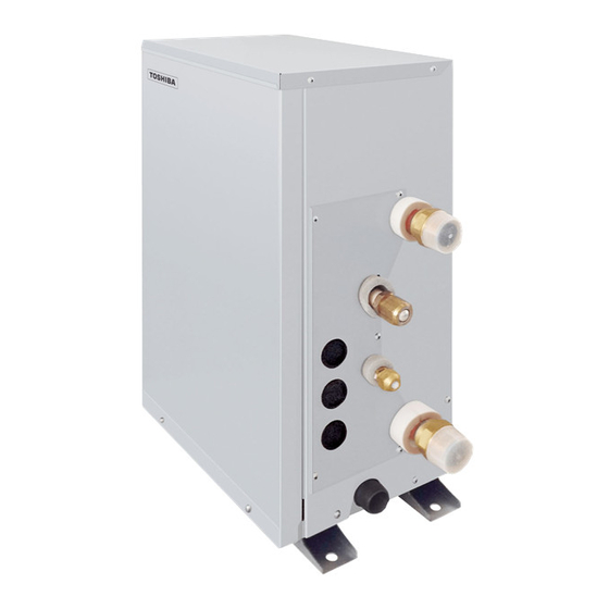
- Page 1 HOT WATER MODULE (MULTI TYPE) Installation Manual R410A For commercial use Indoor Unit Model name: <Mid temperature Hot Water Module> MMW-UP0271LQ-E MMW-UP0561LQ-E English...
-
Page 2: Table Of Contents
– 1 – Original instruction Please read this Installation Manual carefully before installing the hot water module. • This Manual describes the installation method of the hot water module. • For installation of the outdoor unit, follow the Installation Manual attached to the outdoor unit. ADOPTION OF R410A REFRIGERANT This Hot Water Module uses R410A an environmentally friendly refrigerant. - Page 3 • The qualified installer is a person who installs, maintains, relocates and removes the air conditioners (including the hot water modules) made by Toshiba Carrier Corporation. He or she has been trained to install, maintain, relocate and remove the air conditioners (including the hot water modules) made...
-
Page 4: Precautions For Safety
– 3 – Precautions for safety • Do not touch the plate heat exchanger of the unit. You may injure yourself if you do so. If the plate heat exchanger must be touched for The manufacturer shall not assume any liability for the damage caused some reason, first put on protective gloves and safety work clothing, by not observing the description of this manual. - Page 5 • To transport the hot water module, do not take hold of the bands • When the hot water module has been installed or relocated, follow the around the packing carton. You may injure yourself if the bands instructions in the Installation Manual and purge the air completely so should break.
- Page 6 – 5 – • Under no circumstances the power wire must not be extended. Relocation Connection trouble in the places where the wire is extended may give • Only a qualified installer (*1) or qualified service person (*1) is rise to smoking and/or a fire. allowed to relocate the hot water module.
-
Page 7: Accessory Parts
Accessory parts Warning indications on the hot water module Warning indication Description Part name Shape Usage Hand over to customers WARNING Installation Manual This manual (For other languages that do not appear in this Installation Manual, please refer to the enclosed CD-R.) WARNING ELECTRICAL SHOCK HAZARD Hand over to customers... -
Page 8: System Control Of Hot Water Module
– 7 – System control of Hot Water Module 3.1 System able to be combined for SMMS-e, SMMS-u and SHRM-e Series (MMY-***) The Mid temperature Hot water module (M-HWM) is connectable to SMMS-e, SMMS-u and SHRM-e. In case of connecting at least one Hot water module in SHRM-e system, all of Flow Selector unit type should be Single port type Flow Selector unit (long piping model) or Multi port type Flow Selector unit. - Page 9 (*1): Ratio of connected total indoor unit capability to outdoor unit capability ▼Figure 1 (*2): Maximum indoor connection capacity is varied depending on the height difference between indoor unit H2, M-HWM: Mid temperature Hot water module H4, H5. Follower unit Combination of indoor units SHRM-e H2, H4, H5 ≤...
- Page 10 The capacity code of the Hot water module is different from the capacity code of the standard indoor unit. M-HWM: Mid temperature Hot water module Mid temperature Hot water module MMW-UP0271LQ-E MMW-UP0561LQ-E Capacity rank type Total capacity code of indoor units...
- Page 11 37.7 to 66.7 The capacity code of the Hot water module is different from the capacity code of the standard indoor unit. MMY-UP6011HT8P-E 39.0 to 69.0 Mid temperature Hot water module MMW-UP0271LQ-E MMW-UP0561LQ-E MMY-UP6211HT8P-E 40.3 to 71.3 MMY-UP6411HT8P-E 41.6 to 73.6...
- Page 12 ▼Capacity code of Hot water module The capacity code of the Hot water module is different from the capacity code of the standard indoor unit. Mid temperature Hot water module MMW-UP0271LQ-E MMW-UP0561LQ-E Capacity rank type Capacity code Equivalent to HP...
- Page 13 Example of Installation for Hot Water Module water piping GENERAL NOTE • To install the hot water module, connect the pump and line heater, (procured locally). • Do not connect more than one hot water module to one pump and one line heater, (procured locally). •...
- Page 14 – 13 – HWM: Hot Water Module Sample 2. Procured locally Expansion vessel Air vent valve Auxiliary heat Isolating Pressure relief valve source Set: 0.3 MPa valve Booster Heater For heating applications Strainer (Fan coils, radiators, under (30 to 40 floor) meshes) Line...
- Page 15 8.0 to 20.0 ▼Capacity code of Mid temperature Hot water module The capacity code of the Hot water module is different from the capacity code of the standard indoor unit. Mid temperature Hot water module MMW-UP0271LQ-E MMW-UP0561LQ-E Capacity rank type Capacity code...
- Page 16 – 15 – ▼Figure 1 M-HWM: Mid temperature Hot Water Module <Lower outdoor units > <Upper outdoor units> For M-HWM connections, height difference restrictions between standard Standard indoor units (H2), between M-HWM units (H3), and between standard indoor unit indoor units and M-HWM units (H4) Standard indoor H2 ≤...
- Page 17 Example of Installation for Hot Water Module water piping for MiNi-SMMS-e series (MCY-***) GENERAL NOTE • To install the hot water module, connect the pump and line heater, (procured locally). • Do not connect more than one hot water module to one pump and one line heater, (procured locally). •...
-
Page 18: Selection Of Installation Place
– 17 – Selection of installation place CAUTION • Do not install hot water module in a place where water freezes. Avoid installing in the following places • Do not install the hot water module in a place where combustible gas may leak. Select a location for the indoor unit where the cool or warm air will circulate evenly. -
Page 19: Installation
Installation Installation atmosphere Installation atmosphere of the unit is as follows. Be careful of installation atmosphere. It becomes a cause of failure of a product by dewing or freezing. CAUTION Dry-bulb temp. (°C) 5 to 32 Strictly comply with the following rules to prevent damage of the hot water modules and human injury. Wet-bulb temp. - Page 20 – 19 – External dimensions Fixing the hot water module 1. Fix the hot water module with M8 anchor bolts at 4 (Unit: mm) positions. 20 mm projection is appropriate for an to floor anchor bolt. (Unit: mm) WARNING 4-14×12 •...
-
Page 21: Water Piping
Water piping REQUIREMENT • Fix the unit in a horizontal position. WARNING When unit is fixed to slant, it may cause overflow of drainage. • Install the unit within the dimension according to the figure below. • Install water pipes according to the regulations of respective countries. •... - Page 22 • Follow the table below to select a line heater (procured locally) within the range of 40 to 50% of the hot water module's rated capacity. Hot water module model name Capacity of line heater (kW) MMW-UP0271LQ-E 3.2~4.0 MMW-UP0561LQ-E 6.4~8.0...
- Page 23 Characteristics of hot water module flow rate and pressure loss The following graph shows the range of flow rates used for the hot water module, and the characteristic pressure losses. Use this as an aid in the local pump procurement process. 027type 056type Min.
-
Page 24: Drain Piping
– 23 – Drain piping Connecting drain pipe Wrap some sealing tape around the screw part to avoid water leak. CAUTION REQUIREMENT • Connect the hard vinyl chloride pipes certainly so that water does not leak by using adhesive agent for vinyl •... -
Page 25: Refrigerant Piping
Refrigerant piping Heat insulating process • After drain check, covering the heat insulator for drain connecting section, wrap the drain pipe with heat insulator Projection margin in flaring: B (Unit: mm) (Locally procured) without clearance from the end of the drain pipe connecting port of the hot water module. CAUTION Outer dia. - Page 26 – 25 – Airtight test / air purge, etc. Heat insulation process • Use the tightening torque levels as listed in the table below. For air tightness test, adding refrigerant, refer to the Apply heat insulation for the pipes separately at liquid Outer dia.
-
Page 27: Electrical Connection
Electrical connection Power supply WARNING Power supply 220 - 240 V ~, 50 Hz Power supply switch / circuit breaker or power supply wiring / fuse rating for indoor units should be selected by the accumulated total current values of the indoor units. •... - Page 28 – 27 – <In the case of combining with outdoor units of Super Modular Multi System u series (SMMS-u)> <In the case of combining with outdoor units other than Super Modular Multi System u series (SMMS-u)> Follow the wiring specifications in the table below even when units other than U series are mixed in the indoor units Control wiring between indoor units, and outdoor unit (L2, L3) and remote controllers to be connected.
- Page 29 Remote controller wiring H-HWM H-HWM H-HWM H-HWM • 2-core with non-polarity wire is used for the remote controller wiring and group remote controllers wiring. Remote Correct controller Remote controller wiring, remote controller inter-unit Wire size: 0.5 mm² to 2.0 mm² wiring wiring (Max.
- Page 30 – 29 – Wiring between indoor (including hot water module) and outdoor Wire connection units REQUIREMENT • Connect the wires matching the terminal numbers. Incorrect connection causes a trouble. NOTE • Pass the wires through the bushing of wire connection holes of the hot water module. A wiring diagram below is an example for connection to SMMS-u series.
- Page 31 Wiring for Flow selector unit (FS unit) for SHRM-e Relay Connect communication wire of FS unit to terminal A, B (no polarity) of Hot Water Module. when the Hot water module connects to SHRM-e system. Hot water module output signal Output function wire External 黒...
- Page 32 – 31 – Address setup Setting method for 115 to 200% connection compared to outdoor unit capacity Set up the addresses as per the Installation Manual supplied with the outdoor unit. (Only SMMS-i, SMMS-e and SMMS-u operate separately) Relative to outdoor unit capacity, when the connection capacity of HWM+FCU (indoor unit) is 115 to 200% (but HWM ≤...
-
Page 33: Applicable Controls
Applicable controls Group control Push OFF timer button to confirm the selected indoor unit. In a group control, a remote controller can control up to REQUIREMENT maximum 8 or 16 units. (Depending on the outdoor unit.) When the air conditioner (including the Hot water •... -
Page 34: Test Run
– 33 – Test run Items to check before conducting a test run Check the following items before the test run. The numbers in (parentheses) are the chapter numbers in the table Before test run Wired remote controller of contents of the installation manual. -
Page 35: Maintenance
Maintenance Troubleshooting ▼Periodic Maintenance Confirmation and check • For environmental conservation, it is strongly recommended that the indoor and outdoor units of the air conditioner (including hot water module) in use be cleaned and maintained regularly to ensure efficient operation of the air conditioner. - Page 36 – 35 – Check method On the wired remote controller, central control remote controller and the interface P.C. board of the outdoor unit (I/F), a check display LCD (Remote controller) or 7-segment display (on the outdoor interface P.C. board) to display the operation is provided.
- Page 37 Check code Outdoor unit 7-segment display Check code name Judging device Wired remote controller display Auxiliary code 01: TL1 sensor 02: TL2 sensor TL1,TL2 or TL3 sensor trouble 03: TL3 sensor — TO sensor trouble 01: TG1 sensor 02: TG2 sensor TG1,TG2 or TG3 sensor trouble 03: TG3 sensor —...
- Page 38 – 37 – Check code Outdoor unit 7-segment display Check code name Judging device Wired remote controller display Auxiliary code — — Model mismatch of outdoor unit Hot water module — — Indoor unit centre unit duplicated Indoor unit — Outdoor unit line address duplicated —...
- Page 39 Check code Outdoor unit 7-segment display Check code name Judging device Wired remote controller display Auxiliary code 01: Comp. 1 side 1 : Comp. 1 side 02: Comp. 2 side 2 : Comp. 2 side IPM short protection trouble Compressor inverter 03: Comp.
- Page 40 – 39 – Warnings on Refrigerant Leakage Important Check of Concentration Limit The room in which the air conditioner (including hot water module) is to be installed requires a design that 2) When there is an effective opening with the adjacent room for ventilation of leaking refrigerant gas (opening in the event of refrigerant gas leaking out, its concentration will not exceed a set limit.
- Page 41 79-EN 80-EN – 40 –...
- Page 42 EB99841701 (DH91307701)
Need help?
Do you have a question about the MMW-UP0271LQ-E and is the answer not in the manual?
Questions and answers