Table of Contents
Advertisement
Quick Links
Advertisement
Table of Contents

Subscribe to Our Youtube Channel
Related Manuals for Kobold DPT Series


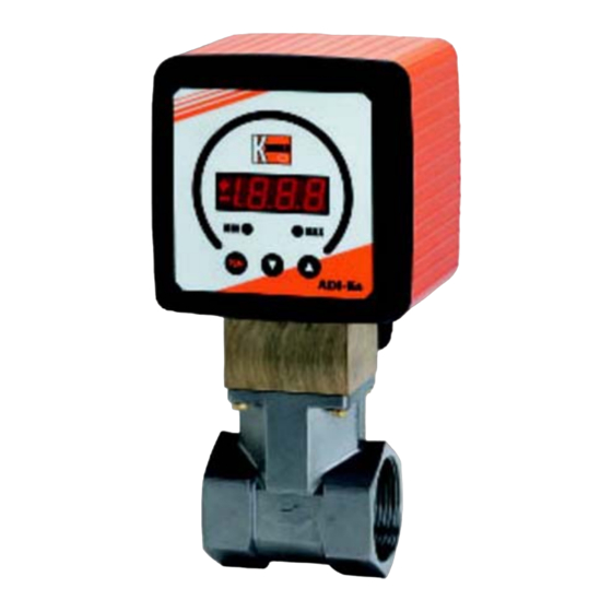
Summary of Contents for Kobold DPT Series
- Page 1 Operating Instructions Torsion Paddle Flow Meter / Monitor Model: DPT-...
-
Page 2: Table Of Contents
We don’t accept warranty and liability claims neither upon this publication nor in case of improper treatment of the described products. The document may contain technical inaccuracies and typographical errors. The content will be revised on a regular basis. These changes will be implemented in later versions. - Page 3 Manufactured and sold by: Kobold Messring GmbH Nordring 22-24 D-65719 Hofheim Tel.: +49(0)6192-2990 Fax: +49(0)6192-23398 E-Mail: info.de@kobold.com Internet: www.kobold.com DPT K05/0323 page 3...
-
Page 4: Note
Please read these operating instructions before unpacking and putting the unit into operation. Follow the instructions precisely as described herein. The instruction manuals on our website www.kobold.com are always for currently manufactured version of our products. Due to technical changes, the instruction manuals available online may not always correspond to the product version you have purchased. -
Page 5: Regulation Use
4. Regulation Use Any use of the device, which exceeds the manufacturer’s specification, may invalidate its warranty. Therefore, any resulting damage is not the responsibility of the manufacturer. The user assumes all risk for such usage. 5. Operating Principle to the diaphragm plate principle. A flat torsion spring acts simultaneously as a mount for the paddle and as an elastic force. -
Page 6: Mechanical Connection
6. Mechanical Connection 6.1 Check Service Conditions: Flow quantity Max. operating pressure Max. operating temperature Medium Mounting position 6.2 Installation Flow in direction of arrow (horizontal) Avoid pressure and tensile loads Mechanically fix inlet and outlet lines at distances of 50 mm from the connections ... -
Page 7: Electrical Connection
7. Electrical Connection 7.1 General Attention! Make sure that the voltage values of your system correspond with the voltage values of the Flow Meter. Make sure that the supply wires are de-energised. Connect the supply voltage and the output signals to the plug connector PINs as shown below. -
Page 8: Adi-Evaluation Electronic
7.4 ADI-Evaluation Electronic To avoid damaging the device during electrical connection, the electrician should take suitable precautions against electrostatic discharge (e.s.d.). The supply voltage for the indicating unit and the optional switching outputs are connected to terminal block 1 according to the wiring diagram below (KB1). Sensor signal and the pickup supply can be connected to terminal block 2 (KB2). -
Page 9: Commissioning
8. Commissioning 8.1 Setting Compact Electronics 8.1.1 Programming Connect the compact electronics according to the previous wiring diagram and apply the specified voltage. The measuring range (upper range value) is displayed for 3 seconds after switch-on. 8.1.2 Key Function Standard mode (measuring mode) : pressing 3 sec. - Page 10 8.1.4 Value Setting You can select value setting in the main menu item (for example: Switching point, "SPo") by pressing the "" key. The structure shown below illustrates the universal routine for changing individual parameters. from the main menu item 1.
- Page 11 8.1.5 Set-up Mode DPT K05/0323 page 11...
- Page 12 page 12 DPT K05/0323...
- Page 13 8.1.6 Main Menu Items Switching point The switching point is entered in menu item "SPo, SP1, SP2". A value in the range 000 to 999 may be chosen. A decimal point position is also assigned to this value. The position of the decimal point can be set after the first, second or last position (no decimal point).
- Page 14 If the window point (duo point) is lower than or equal to the switching point, an error message is displayed (Er4), its value is then deleted and thus its function is disabled (applies to window point and switching point setting). Value setting is similar to switching point setting.
- Page 15 Filter The filter function "Filt" generates the sliding average value from the measured values. The following values are available (see section 8.1.3 Settings): 1 / 2 / 4 / 8 / 16 / 32 / 64 The filter value determines the dynamic behaviour of the indicated value: high values results in a slow display response.
-
Page 16: Setting Adi Evaluation Electronic
Work on the sensor and electronics should only be carried out by the supplier, otherwise the guarantee is nullified. 10. Technical Information Operating instructions, data sheet, approvals and further information via the QR code on the device or via www.kobold.com page 16 DPT K05/0323... -
Page 17: Order Codes
11. Order Codes Operating instructions, data sheet, approvals and further information via the QR code on the device or via www.kobold.com 12. Dimensions Operating instructions, data sheet, approvals and further information via the QR code on the device or via www.kobold.com... -
Page 18: Disposal
13. Disposal Note! Avoid environmental damage caused by media-contaminated parts Dispose of the device and packaging in an environmentally friendly manner Comply with applicable national and international disposal regulations and environmental regulations. Batteries Batteries containing pollutants are marked with a sign consisting of a crossed-out garbage can and the chemical symbol (Cd, Hg, Li or Pb) of the heavy metal that is decisive for the classification as containing pollutants: 1. -
Page 19: Eu Declaration Of Conformance
14. EU Declaration of Conformance We, KOBOLD Messring GmbH, Hofheim-Ts, Germany, declare under our sole responsibility that the product: Torsion Paddle Flow Meter / Monitor model: DPT -... to which this declaration relates is in conformity with the standards noted below:...
Need help?
Do you have a question about the DPT Series and is the answer not in the manual?
Questions and answers