Table of Contents
Advertisement
Quick Links
Battery BOX
Quick Installation Manual
1
Overview
.
1
2
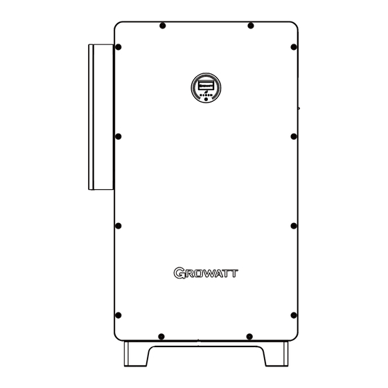
(1)Front panel
(6)BMS communication port
(10)Network communication port (11)Battery terminal
(14)LOAD terminal
Notes:
1.The content of this document is continually reviewed and amended, where necessary. Growatt reserves the right to make changes to the
material at any time and without notice. Unless otherwise agreed, this document is for quick installation guidance only. All information and
suggestions in this document do not constitute a warranty of any kind, express or implied. Growatt reserves all rights for final explanation.
2.This document is for quick installation guidance only. For details, please refer to the User Manual.
3.Machine damage caused by failure to follow the instructions is not covered under any warranty.
2
.
Installation
System overview
Primary Load
PCS
BAT
Phone
2.2
Floor-mounted installation
1
Notes:
1.When determining the installation position of the inverter, please consider the position of the batteries and the distribution panel.
2.For export limitation, you are advised to connect an energy meter and current transformers to the inverter.
Output Power
100.0
KW
3
5
4
6 7 8 9
(2)OLED display screen
(7)Parallel communication port
(15)Base
Grid
Bypass
Breaker
Load
Breaker
Grid
Breaker
Meter
Secondary Load
2
Notes:
When drilling holes, avoid the
water pipes and power cables
buried under the ground.
10 11 12
(3)Battery status indicator
(8)Monitor communication port
(12)BMS power supply port
2.1
Installation requirements
≥1000mm
≥1000mm
T
3
WIT 50-100K-AU Quick Guide
13 14
(4)Push button
(5)System indicator
(9)USB port
(13)GRID terminal
≥1000mm
15
574.5mm
Advertisement
Table of Contents

Subscribe to Our Youtube Channel
Related Manuals for Growatt WIT 50-100K-AU


Summary of Contents for Growatt WIT 50-100K-AU
- Page 1 Unless otherwise agreed, this document is for quick installation guidance only. All information and suggestions in this document do not constitute a warranty of any kind, express or implied. Growatt reserves all rights for final explanation.
- Page 2 Connecting cables Please prepare the cables listed below before electrical connections. Recommend Cable Type specifications Notes: A multiple-core copper cable (yellow and Grounding cable 50mm 1.Make sure all switches are green) OFF before connecting the GRID cable A multi-core copper cable 120mm -300mm cables.
- Page 3 Installing the communication cable Parallel communication port BMS communication port Parallel communication port BMS Communication port description(COM2) description(BMS-COM) Description Description No. Description No. Description Wakeup+ CANL 24V.S CAN2_H Wakeup- CAN.GND GND.S CAN2_L RS485A3 CAN1_H RS485_1A RS485B3 CAN1_L RS485_1A CANH GND.S Network communication port CAN2_H RS485_5A...
- Page 4 On-grid indicator Push button Off-grid indicator 3.5.6 Communication module installation Service and contact Shenzhen Growatt New Energy Co., Ltd 4-13/F, Building A, Sino-German (Europe) Industrial Park, Hangcheng Ave, Bao'an District, Shenzhen, China +86 755 2747 1942 service@ginverter.com www.ginverter.com Growatt New Energy...
Need help?
Do you have a question about the WIT 50-100K-AU and is the answer not in the manual?
Questions and answers