Sign In
Upload
Manuals
Brands
IFM Manuals
Measuring Instruments
SD1540
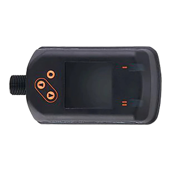
User Manuals: IFM SD1540 Compressed air meter
Manuals and User Guides for IFM SD1540 Compressed air meter. We have
2
IFM SD1540 Compressed air meter manuals available for free PDF download: Operating Instructions Manual
IFM SD1540 Operating Instructions Manual (49 pages)
Flow meter compressed air
Brand:
IFM
| Category:
Measuring Instruments
| Size: 0 MB
Table of Contents
Table of Contents
2
Preliminary Note
4
1�1 Symbols Used
4
1�2 Warnings Used
5
Safety Instructions
5
Functions and Features
6
Function
6
4�1 Processing of the Measured Signals
6
4�2 Switching Output
7
4�3 Analogue Output
8
4�4 Consumed Quantity Monitoring
10
4�4�1 Meter Reading
10
4�4�2 Counter Reset
10
4�4�3 Consumed Quantity Monitoring Via Pulse Signals
11
4�4�4 Consumed Quantity Monitoring Via Preset Counter
11
4�5 Measured Value Damping
12
4�6 Low Flow Cut-Off
12
4�7 Simulation
12
4�8 Colour of the Characters in the Display
13
4�9 IO-Link
14
4�9�1 Additional Functions Via IO-Link
14
Installation
15
5�1 Installation Location
15
5�2 Installation Conditions
15
5�3 Installation Position
16
5�4 Installation Example Using the Process Adapter E40195
17
Electrical Connection
18
Operating and Display Elements
20
Menu
21
8�1 Process Value Display (RUN)
21
8�2 Main Menu
22
8�3 Extended Functions
23
8�4 Submenu OUT1
24
8�5 Submenu OUT2
26
8�6 Submenu CFG
28
8�7 Submenus MEM, DIS
30
8�8 Submenus COLR, SIM
32
Set
34
Parameter Setting
34
10�1 Parameter Setting in General
35
10�1�1 Select Submenu
35
10�1�2 Change to the Process Value Display (RUN Mode)
35
10�1�3 Lock / Unlock
36
10�1�4 Timeout
36
10�2 Settings for Volumetric Flow Monitoring
36
10�2�1 Adaptation to the Internal Pipe Diameter
36
10�2�2 Limit Monitoring OUT1 or OUT2 / Hysteresis Function
36
10�2�3 Limit Monitoring OUT1 or OUT2 / Window Function
37
10�2�4 Analogue Signal Volumetric Flow OUT2
37
10�3 Settings for Consumed Quantity Monitoring
37
10�3�1 Quantity Monitoring by Pulse Signal OUT1 or OUT2
37
10�3�2 Quantity Monitoring by Preset Counter OUT1 or OUT2
37
10�3�3 Manual Counter Reset
38
10�3�4 Time-Controlled Counter Reset
38
10�3�5 Deactivation of the Counter Reset
38
10�3�6 Counter Reset Using an External Signal
38
10�4 Settings for Temperature Monitoring
38
10�4�1 Limit Monitoring OUT1 or OUT2 / Hysteresis Function
38
10�4�2 Limit Monitoring OUT1 or OUT2 / Window Function
38
10�4�3 Analogue Signal Temperature OUT2
39
10�5 Settings for Pressure Monitoring
39
10�5�1 Limit Monitoring OUT1 or OUT2 / Hysteresis Function
39
10�5�2 Limit Monitoring OUT1 or OUT2 / Window Function
39
10�5�3 Analogue Signal Pressure OUT2
39
10�6 User Settings (Optional)
40
10�6�1 Standard Display
40
10�6�2 Standard Unit of Measurement for Volumetric Flow
40
10�6�3 Standard Unit of Measurement for Temperature
40
10�6�4 Standard Unit of Measurement for Pressure
40
10�6�5 Measured Value Damping
41
10�6�6 Output Logic
41
10�6�7 Low Flow Cut-Off
41
10�6�8 Standard Conditions
41
10�6�9 Zero-Point Calibration Pressure
41
10�6�10 Colour of the Characters in the Display
42
10�6�11 Switch-On /Switch-Off Delay
42
10�6�12 Error Behaviour of the Outputs
43
10�6�13 Restore Factory Setting
43
10�7 Diagnostic Functions
44
10�7�1 Read Min/Max Values
44
10�7�2 Simulation
44
Operation
45
Error Correction
45
Maintenance, Repair and Disposal
47
Factory Setting
48
Advertisement
IFM SD1540 Operating Instructions Manual (46 pages)
Flow meter compressed air
Brand:
IFM
| Category:
Measuring Instruments
| Size: 1 MB
Table of Contents
Table of Contents
2
Preliminary Note
4
Symbols Used
4
Warnings
4
Safety Instructions
5
Intended Use
6
Application Area
6
Function
7
Output OUT1 Selection Options
7
Output OUT2 Selection Options
7
IO-Link
7
Mounting
9
Installation Location
9
Installation Position
9
Interference
10
Process Connection
10
Electrical Connection
11
Operating and Display Elements
13
Menu
14
Menu Overview
14
Main Menu and Submenus
14
Set-Up
22
Parameter Setting
23
Parameter Setting Via the Unit Keys
23
Parameter Setting Via IO-Link
23
Output Configuration
24
Switching Signal
24
Analogue Signal
25
Consumed Quantity Monitoring (Totaliser Function)
27
Pulse Signal Totaliser
27
Switching Signal Totaliser
28
Output off
29
Application Configuration
30
Standard Unit of Measurement
30
Damping
30
Output Polarity of the Switching Outputs
30
Internal Pipe Diameter
31
Process Value for OUT1 and OUT2
31
Low Flow Cut-Off
31
Standard Conditions
32
Zero Calibration
32
Switching Delay
33
Error Behaviour of the Outputs
33
Totaliser Reset
34
Lock / Unlock
35
Device Reset
36
Display
36
Display Layout
36
Display Update Rate
37
Display Rotation
37
Display Brightness
38
Display Colour Setting
38
Diagnosis
40
Read Totaliser Values
40
Memory
40
Service Functions
41
Simulation
41
Optical Localisation
42
Device Information
42
Troubleshooting
44
Warning Messages
44
Error Messages
44
Maintenance, Repair and Disposal
45
Factory Settings
46
Advertisement
Related Products
IFM SDG070
IFM SDG080
IFM SDG100
IFM SD25 Series
IFM SD55 Series
IFM SD95 Series
IFM SD26 Series
IFM SDG082
IFM SDG087
IFM SDG102
IFM Categories
Accessories
Measuring Instruments
Security Sensors
Rfid Systems
Controller
More IFM Manuals
Login
Sign In
OR
Sign in with Facebook
Sign in with Google
Upload manual
Upload from disk
Upload from URL