
Subscribe to Our Youtube Channel
Related Manuals for STIEBEL ELTRON DEL 13 Plus AU


Summary of Contents for STIEBEL ELTRON DEL 13 Plus AU
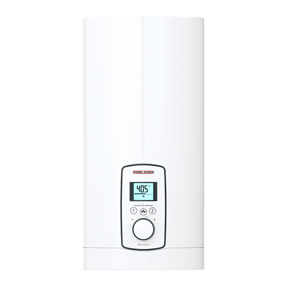
- Page 1 OPERATION AND INSTALLATION Electronically controlled comfort instantaneous water heater » DEL 13 Plus AU » DEL 18 Plus AU » DEL 27 Plus AU...
-
Page 2: Table Of Contents
CONTENTS SPECIAL INFORMATION 13.8 Operation with preheated water ���������������������������� 15 13.9 Horizontal installation of the appliance �������������������� 15 OPERATION Service information ���������������������������������������� 15 General information �����������������������������������������3 Troubleshooting �������������������������������������������� 16 Safety instructions ����������������������������������������������� 3 15.1 Fault code display ���������������������������������������������� 16 Other symbols in this documentation ����������������������� 4 Units of measurement ������������������������������������������... -
Page 3: Special Information
SPECiAL iNfOrmATiON | OPErATiON General information SPECiAL iNfOrmATiON OPErATiON - The appliance may be used by children aged 3 General information and older and persons with reduced physical, The chapters "Special information" and "Operation" are intended sensory or mental capabilities or a lack of ex- for both users and qualified contractors. -
Page 4: Other Symbols In This Documentation
OPErATiON Safety Other symbols in this documentation CAUTION Burns If operating with preheated water, e.g. if using a solar Note thermal system, observe the following information: General information is identified by the adjacent symbol. - The DHW temperature may exceed the set tempera- f Read these texts carefully. -
Page 5: Settings And Displays
OPErATiON Settings and displays Display symbols You can store different set temperatures and call them up quickly. With the ECO function, the flow rate is limited to 3 preset levels. The appliance has setting options for a temperature limit (Tmax function, user) and internal anti-scalding protection (qualified contractor). -
Page 6: Temperature Limit Tmax (User)
OPErATiON Settings and displays Temperature limit Tmax (user) Selecting ECO level The temperature limit allows you as a user to restrict the adjusta- ECO level Display flow rate limitation ble set temperature at the appliance to a maximum value. Level 1 8 l/min (factory setting) Level 2 7 l/min... -
Page 7: Cleaning, Care And Maintenance
OPErATiON | iNSTALLATiON Cleaning, care and maintenance iNSTALLATiON Cleaning, care and maintenance f Never use abrasive or corrosive cleaning agents. A damp cloth is sufficient for cleaning the appliance. f Check the taps regularly. Limescale deposits at the tap out- Safety lets can be removed using commercially available descaling agents. -
Page 8: Appliance Description
iNSTALLATiON Appliance description Preparation Test for delivery temperature performance The appliance is to be tested according to AS 3498 as a 50 °C- limited water heater. The option 1 illustrated in figure A.1 of the Installation location Appendix A applies to the appliance. Material losses Valve 1 Install the appliance in a room free from the risk of frost. -
Page 9: Water Installation
iNSTALLATiON installation Water installation 10.1 Standard installation f Flush the water line thoroughly. Opening the appliance Taps/valves Use appropriate pressure taps. Open vented taps are not per- missible. Permissible water line materials - Cold water inlet line: Pipes made from galvanised steel, stainless steel, copper or plastic - DHW outlet line: Stainless steel pipe, copper pipe or plastic pipe... - Page 10 iNSTALLATiON installation Preparing the water connection Material losses Carry out all water connection and installation work in accordance with regulations. 5 Nm 5 Nm 5 Nm f Remove the transport protection plugs from the appliance 5 Nm pipe connections. f Bend the power cable 45° upwards. f Remove the caps from the tees.
-
Page 11: Commissioning
iNSTALLATiON Commissioning CAUTION Burns Material losses If operating with preheated water, e.g. if using a solar Observe the type plate. The specified rated voltage must thermal system, the internal anti-scalding protection and match the mains voltage. the temperature limit Tmax, which can be set by the user, may be exceeded. -
Page 12: Recommissioning
iNSTALLATiON Appliance shutdown Fit the appliance cover 11.2.1 Appliance handover f Explain the appliance function to users and familiarise them with how it works. f Make the user aware of potential dangers, especially the risk of scalding. f Hand over the instructions. 11.3 Recommissioning Material losses To ensure that the bare wire heating system is not dam-... -
Page 13: Power Cable
iNSTALLATiON Alternative installation methods 13.3 Electrical connection on finished walls Note This type of connection changes the IP rating of the ap- pliance. f Change the type plate. Cross out "IP 25" and mark the box "IP 24". Use a ballpoint pen to do this. 1 Cable routing f Reposition the mains terminal from the bottom to the top. -
Page 14: Wall Mounting Bracket When Replacing An Appliance
iNSTALLATiON Alternative installation methods 13.6 Installation with offset tiles f Fit the strainer and the plastic profile washer in the tee for the cold water inlet. Material losses The strainer must be fitted for the appliance to function. 1 Minimum contact area of the appliance f When replacing an appliance, check whether the 2 Maximum tile offset strainer is installed. -
Page 15: Operation With Preheated Water
iNSTALLATiON Service information 13.8 Operation with preheated water 14. Service information You can restrict the maximum inlet temperature by installing a Overview of connections central thermostatic valve. 13.9 Horizontal installation of the appliance Note For the horizontal installation alternative, please note the following points: - Installation is only permissible with direct wall mounting. -
Page 16: Troubleshooting
iNSTALLATiON Troubleshooting 15. Troubleshooting indicator options for diagnostic traffic light (LED) WARNING Electrocution Illuminates in the event of a fault To test the appliance, it must be connected to the power Yellow Illuminates in heating mode/flashes when output limit supply. reached Green Flashing: Appliance connected to power supply... -
Page 17: Maintenance
iNSTALLATiON maintenance 16. Maintenance 17. Specification 17.1 Dimensions and connections WARNING Electrocution Before any work on the appliance, disconnect all poles from the power supply. ≤ 20 This appliance contains capacitors which are discharged when disconnected from the power supply. The capacitor discharge voltage may briefly exceed 60 V DC. -
Page 18: Wiring Diagram
Connected load in kW 38 °C DHW output in l/min. rated voltage Cold water inlet temperature 380 V 400 V 415 V 5 °C 10 °C 15 °C 20 °C DEL 13 Plus AU 12.2 13.5 10.7 14.5 11.5 DEL 18 Plus AU 16.2 10.1 12.9 11.2 14.3... -
Page 19: Data Table
This document is made of recyclable paper. the source code. Stiebel Eltron therefore provides further infor- f Dispose of the document at the end of the ap- mation regarding third supplier software that it uses under the pliance‘s life cycle in accordance with national... - Page 20 Contact person: Customer Service Representative The Stiebel Eltron warranty for the unit is in addition to any rights E-mail: service@stiebel-eltron.com.au and remedies you may have under the Australian Consumer Law.
- Page 21 NOTES www.stiebel-eltron.com DEL Plus AU |...
- Page 22 NOTES | DEL Plus AU www.stiebel-eltron.com...
- Page 23 NOTES www.stiebel-eltron.com DEL Plus AU |...
- Page 24 Co m f o r t t h r o u gh Te c h n o l o g y STIEBEL ELTRON International GmbH Dr.-Stiebel-Straße 33 | 37603 Holzminden | Germany info@stiebel-eltron.com | www.stiebel-eltron.com 4 < A M H C M O = c i c c d f >...
Need help?
Do you have a question about the DEL 13 Plus AU and is the answer not in the manual?
Questions and answers