STIEBEL ELTRON DEL 18 Plus Operation And Installation
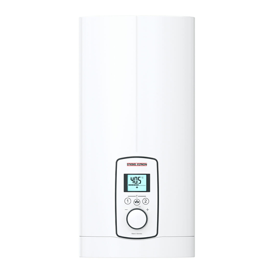
Electronically controlled comfort instantaneous water heater
Hide thumbs
Also See for DEL 18 Plus:
- Operation and installation manual (108 pages) ,
- Manual (24 pages) ,
- Operation and installation (20 pages)
Table of Contents
Advertisement
Quick Links
BEDIENUNG UND INSTALLATION
OPERATION AND INSTALLATION
UTILISATION ET INSTALLATION
BEDIENING EN INSTALLATIE
OBSŁUGA I INSTALACJA
Elektronisch geregelter Komfort-Durchlauferhitzer | Electronically controlled
comfort instantaneous water heater | Chauffe-eau instantané confort à régulation
électronique | Elektronisch geregelde comfort-doorstromer | Elektronicznie
regulowany komfortowy przepływowy ogrzewacz wody
» DEL 18/21/24 Plus
» DEL 27 Plus
Advertisement
Table of Contents
Troubleshooting

Subscribe to Our Youtube Channel
Related Manuals for STIEBEL ELTRON DEL 18 Plus


Summary of Contents for STIEBEL ELTRON DEL 18 Plus
- Page 1 BEDIENUNG UND INSTALLATION OPERATION AND INSTALLATION UTILISATION ET INSTALLATION BEDIENING EN INSTALLATIE OBSŁUGA I INSTALACJA Elektronisch geregelter Komfort-Durchlauferhitzer | Electronically controlled comfort instantaneous water heater | Chauffe-eau instantané confort à régulation électronique | Elektronisch geregelde comfort-doorstromer | Elektronicznie regulowany komfortowy przepływowy ogrzewacz wody »...
-
Page 2: Table Of Contents
CoNTENTs SPECIAL INFORMATION 13.8 Lower back panel section installation with threaded fittings on finished walls �������������������������������������� 34 OPERATION 13.9 Wall mounting bracket when replacing appliance ������� 35 General information ��������������������������������������� 23 13.10 Installation with offset tiles ����������������������������������� 35 Safety instructions ���������������������������������������������� 23 13.11 Pivoting appliance cover ��������������������������������������... -
Page 3: Special Information
sPECIAL INForMATIoN | oPErATIoN General information sPECIAL INForMATIoN oPErATIoN - The appliance may be used by children aged 3 General information and older and persons with reduced physical, sensory or mental capabilities or a lack of ex- The chapters "Special information" and "Operation" are intended for both users and qualified contractors. -
Page 4: Other Symbols In This Documentation
oPErATIoN safety Other symbols in this documentation WARNING Injury The appliance may be used by children aged 3 and older Note and persons with reduced physical, sensory or mental General information is identified by the adjacent symbol. capabilities or a lack of experience and know-how, pro- f Read these texts carefully. -
Page 5: Settings And Displays
oPErATIoN settings and displays Setting the temperature Note The appliance is equipped with an air detector that large- ly prevents damage to the heating system. If, during op- eration, air is drawn into the appliance, the appliance shuts down for one minute, thereby protecting the heat- ing system. -
Page 6: Allocating Temperature Memory Buttons
oPErATIoN Cleaning, care and maintenance Allocating temperature memory buttons Saving energy The following recommended settings will result in the lowest en- Memory buttons "1" and "2" can each be assigned a required ergy consumption: temperature. - 38 °C for hand washbasins, showers, bath f Select the required temperature. -
Page 7: Troubleshooting
oPErATIoN Troubleshooting Troubleshooting Problem Cause remedy The appliance will not start despite the There is no power. Check the fuses/MCBs in your distribution board. DHW valve being fully open. The aerator in the tap or the shower head is Clean and/or descale the aerator or shower head. scaled up or soiled. -
Page 8: Installation
INsTALLATIoN safety INsTALLATIoN Appliance description Standard delivery The following are delivered with the appliance: Safety - Wall mounting bracket Only a qualified contractor should carry out installation, commis- - Installation template sioning, maintenance and repair of the appliance. - 2 twin connectors - 3-way ball shut-off valve for cold water General safety instructions - Tee for domestic hot water... -
Page 9: Preparation
INsTALLATIoN Preparation Minimum clearances Load shedding relay (LR 1-A) The load shedding relay for installation in the distribution board provides priority control for the instantaneous water heater when other appliances, such as electric storage heaters, are being op- erated simultaneously. Central thermostatic valve (ZTA 3/4) ≥50 ≥50 Use the thermostatic valve for central premixing when, for ex-... -
Page 10: Standard Installation
INsTALLATIoN Installation 10.1 Standard installation Installing the twin connector Opening the appliance Material losses Carry out all water connection and installation work in accordance with regulations. f Seal and insert the twin connectors. f Open the appliance by holding the fascia at the side and pull- ing forwards away from the appliance cover. -
Page 11: Commissioning
INsTALLATIoN Commissioning Fitting the lower back panel section 1 Diffuser on lower back panel f Fit the lower back panel section into the back panel. Check that both locking tabs are engaged. f Align the mounted appliance by undoing the fixing toggle, aligning the power supply and back panel, and then re-tight- ening the fixing toggle. -
Page 12: Initial Start-Up
INsTALLATIoN Appliance shutdown Changing connected load via jumper slot, DEL 18/21/24 Plus f Tick the selected connected load and rated voltage on the ap- only pliance cover type plate (on both sides). Use a ballpoint pen to do this. If you select a connected load other than the 21 kW factory setting f Secure the appliance cover with the screw. -
Page 13: Electrical Connection From Above On Unfinished Walls
INsTALLATIoN Alternative installation methods 13.1 Electrical connection from above on unfinished 13.2 Electrical connection on unfinished walls with walls short power cable 1 Cable entry installation aid f Prepare the power cable. f Reposition the mains terminal further downwards. To do this, undo the fixing screw. -
Page 14: Water Installation On Finished Walls
INsTALLATIoN Alternative installation methods 13.5 Water installation on finished walls 13.7 Fitting appliance cover over water installation on finished walls Note This type of connection changes the IP rating of the ap- pliance. f Change the type plate. Cross out "IP 25" and mark the box "IP 24". -
Page 15: Wall Mounting Bracket When Replacing Appliance
INsTALLATIoN service information 13.9 Wall mounting bracket when replacing WARNING Electrocution appliance All 4 locking tabs on the programming unit must click into place. The locking tabs must be complete and undam- An existing STIEBEL ELTRON wall mounting bracket may be used aged. -
Page 16: Troubleshooting
INsTALLATIoN Troubleshooting 15. Troubleshooting WARNING Electrocution Note To test the appliance, it must be connected to the power The diagnostic traffic light is displayed when water flows. supply. Indicator options for diagnostic traffic light (LED) Illuminates in the event of a fault Display indication Cause Yellow... -
Page 17: Specification
INsTALLATIoN Specification 17. Specification 17.2 Wiring diagram 3/PE ~ 380-415 V 17.1 Dimensions and connections ≤ 20 1 Power PCB with integral safety switch 2 Bare wire heating system 3 High limit safety cut-out 4 Mains terminal Priority control with LR 1-A DEL Plus b02 Entry electrical cables I Installation on unfinished walls... -
Page 18: Application Areas / Conversion Table
The product data complies with EU regulations relating to the directive on the ecodesign of energy related products (ErP). DEL 18/21/24 Plus DEL 27 Plus 236739 236740 Manufacturer STIEBEL ELTRON STIEBEL ELTRON Load profile Energy efficiency class Energy conversion efficiency Daily power consumption 2.211 2.217... -
Page 19: Data Table
INsTALLATIoN | GUArANTEE | ENVIroNMENT AND rECYCLING Specification 17.9 Data table DEL 18/21/24 Plus DEL 27 Plus 236739 236740 Electrical data Rated voltage Rated output 16.2/19/21.7 18/21/24 19.4/22.6/25.8 24.4 Rated current 27.6/29.5/33.3 29/31/35 30.1/32.2/36.3 37.1 Fuses 32/32/35 32/32/35 32/32/40 Frequency 50/60 50/60 50/-... - Page 20 Deutschland Verkauf Tel. 05531 702-110 | Fax 05531 702-95108 | info-center@stiebel-eltron.de STIEBEL ELTRON GmbH & Co. KG Kundendienst Tel. 05531 702-111 | Fax 05531 702-95890 | kundendienst@stiebel-eltron.de Dr.-Stiebel-Straße 33 | 37603 Holzminden Ersatzteilverkauf Tel. 05531 702-120 | Fax 05531 702-95335 | ersatzteile@stiebel-eltron.de Tel.
Need help?
Do you have a question about the DEL 18 Plus and is the answer not in the manual?
Questions and answers