Hexagon VERIPOS LD900 Commissioning Manual
Hide thumbs
Also See for VERIPOS LD900:
- Installation and operation manual (86 pages) ,
- Installation and operation manual (106 pages)
Table of Contents
Advertisement
Quick Links
Introduction
This commissioning guide will provide the information required to install the VERIPOS LD900 unit with INS, by
detailing how an LD900 should be configured and how an IMU should be mounted, interfaced and configured.
Contents
Introduction
Prerequisites
INS Authorisation
GNSS Heading Antenna Installation
Reference Frames
IMU Placement
IMU Interfacing
Alignment / Calibration
Rotational Offset Adjustment
Configuration
Operation
Troubleshooting
Appendix A – Equipment Required
Appendix B - IMU Performance
The VERIPOS INS system consists of an LD900 (LD900 or LD900M model) receiver, authorised for INS use
and operating in PPP mode with active GNSS heading. The LD900 presently supports integration with two
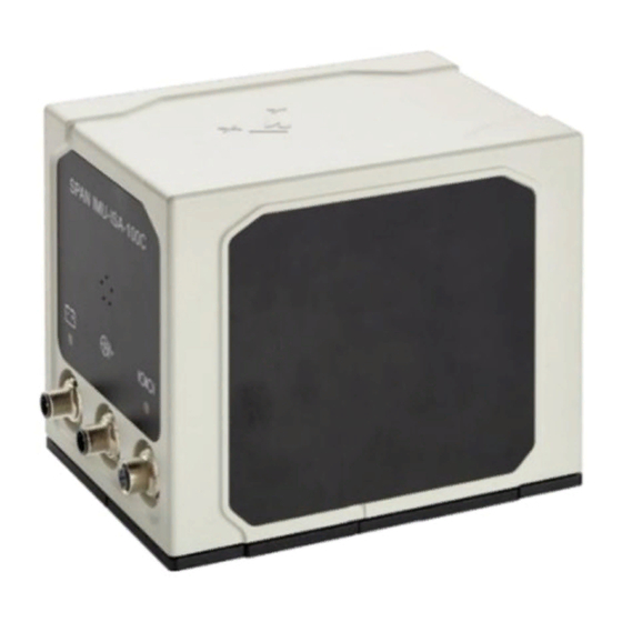
Novatel IMU models, the IMU-ISA-100C and IMU-µIMU-IC:
INS operations can be configured and monitored using the LD900 MMI, or an interfaced Quantum software
system. This guide will provide details for both options.
AB-V-MA-650
JF/RR
LD900 and INS Commissioning Guide
Novatel IMU-ISA-100C (left) and Novatel IMU-µIMU-IC (right)
1 February 2021
1
Advertisement
Table of Contents

Subscribe to Our Youtube Channel
Related Manuals for Hexagon VERIPOS LD900


Summary of Contents for Hexagon VERIPOS LD900
- Page 1 LD900 and INS Commissioning Guide Introduction This commissioning guide will provide the information required to install the VERIPOS LD900 unit with INS, by detailing how an LD900 should be configured and how an IMU should be mounted, interfaced and configured.
-
Page 2: Antenna Separation
VERIPOS project manager, or by email (support.veripos@hexagon.com). The Auth Code will be supplied with a guide explaining how the codes can be applied to the LD900. Note the INS authorisation code includes the GNSS heading functionality. -
Page 3: Antenna Installation
LD900 and INS Commissioning Guide Antenna Installation Optimum results will be easier to achieve with an along ship installation. The heading orientation is computed from the GNSS1 antenna to GNSS2 antenna as illustrated below. In this configuration, the GNSS heading closely reflects the actual vessel heading. - Page 4 LD900 and INS Commissioning Guide Reference Frames It is important to have a basic understanding of reference frames when dealing with INS. Reference frames are especially important when configuring the systems rotational offsets. Two types of reference frames will be considered, the Vessel Reference Frame and the IMU Body Frame.
- Page 5 LD900 and INS Commissioning Guide IMU-µIMU-IC Centre of Navigation Markers IMU-µIMU-IC Centre of Navigation Markers The two figures following show the IMU Body Frame for both supported IMU models. These diagrams highlight the centre of navigation differences between the IMU-ISA-100C and IMU-µIMU-IC models. The different IMU frameworks have pre-configured rotational offsets applied by the system configuration when selected, with the premise of the IMU being mounted with the connectors facing forward along the vessel frame Y-axis.
- Page 6 LD900 and INS Commissioning Guide IMU Placement The following factors need to be considered when installing the IMU. • Mount as close as possible to the vessel centre point of gravity • Mounted on a fabricated plate secured to a flat level surface within the vessel frame. •...
- Page 7 LD900 and INS Commissioning Guide IMU-ISA-100C Base Plate IMU-µIMU-IC Base Plate When the IMU has been mounted in the correct orientation, pre-set rotational offsets will be automatically applied (when the IMU is selected within the LD900 or Quantum), aligning the IMU Frame with the Vessel Frame.
- Page 8 LD900 and INS Commissioning Guide IMU Interfacing Cabling The LD900 will be interfaced to the IMU using RS422 serial data-communications. This section details the LD900 and IMU requirements for INS operations. The diagram below provides an overview of the principal system component interconnections: INS Schematic Example IMU DC Power...
- Page 9 LD900 and INS Commissioning Guide Two isolated DC power sources can be used to power the IMU. Alternatively, the two VIN- and two VIN+ pins can be connected in parallel and connected to a single DC power supply. Ensure that the positive is connected to VIN+ and that negative is connected to VIN-.
- Page 10 LD900 and INS Commissioning Guide With the use of quality shielded data cable, the RS422 interface cable should not exceed 50 metres. Avoid running the interface cable close to noisy power lines, or other electrical noise sources. When checking the IMU health the COM ( ) LED on the IMU can be used as a reference: State Meaning...
-
Page 11: Alignment / Calibration
LD900 and INS Commissioning Guide Alignment / Calibration The IMU and antenna placements must be aligned to the vessel frame. The system configuration requires the following measurements; • Lever arm (IMU to Antenna 1) X (Starboard Positive) Y (Forward Positive) Z (Up Positive) •... - Page 12 LD900 and INS Commissioning Guide INS Translational Offsets AB-V-MA-00650 01 February 2021 JF/RR...
- Page 13 LD900 and INS Commissioning Guide Rotational Offset Adjustment This section will illustrate how the measured rotational alignment offsets (precise offsets) should be adjusted to the default course offset. The following illustrates the adjustments methods for both supported IMU models. IMU-ISA-100C When the X axis of the IMU is offset to starboard by angle “a”.
- Page 14 LD900 and INS Commissioning Guide IMU-µIMU-IC When the Y axis of the IMU is offset to starboard by angle “a”. The Installation Rotation X 0 value is reduced by the measured angle. INS Rotational Offsets – Vessel Plan View When the Z axis of the IMU is offset to starboard by angle “a”. The Installation Rotation Y -90 value is reduced by the measured angle (If the measured value for ‘a’...
- Page 15 LD900 and INS Commissioning Guide Configuration At this stage, the IMU is securely mounted with offsets determined, powered up and connected to a LD900 COM port. The LD900 has been activated for PPP solution, which is converged and stable and the LD900 is ready for configuration.
- Page 16 LD900 and INS Commissioning Guide Return to the home screen and INS status will be unchanged (grey). The GNSS heading can be observed within the INS status. The reported GNSS heading should show alignment with the vessel heading, no other values will be present at this stage.
- Page 17 LD900 and INS Commissioning Guide Installation Rotation The following details how the X (Pitch), Y (Roll) and Z (Yaw) rotational offsets are entered into the LD900. While Installation Rotation is selected click on Edit, followed by tick and using the arrow buttons and tick enter an X value within +/- 180.00.
- Page 18 LD900 and INS Commissioning Guide Quantum Configuration Receiver Management When correctly authorised both Heading and INS areas will be displayed within SETTINGS > System Configuration > Receiver Management showing X Not Configured. If no such areas are shown, then request a Quantum Heading license from the VERIPOS Helpdesk. Click on Edit, found at the bottom right- hand corner of the screen: SETTINGS >...
- Page 19 LD900 and INS Commissioning Guide Enabling INS Within the INS tab initially, only one option will be available, allowing for INS to be DISABLED (or) ENABLED. Toggle this to ENABLED to reveal additional options: Type The two INS IMUs supported for use within Quantum are the IMU-ISA-100C and the IMU- μIMU-IC.
-
Page 20: Operation
LD900 and INS Commissioning Guide Operation The successful configuration of INS can be determined by checking the LD900 MMI Status page and, if used, within the Quantum main page. INS Status (LD900 MMI) The LD900 INS status can be viewed on the MMI by pressing the home button. Before configuration, the INS Icon will be Grey and once configured this will change from Grey to Amber. - Page 21 LD900 and INS Commissioning Guide INS Status (Quantum) INS status or configuration will be visible in Quantum once the LD900 is authorised for INS operations. The status of INS operations is visible within the Quantum sidebar as shown in the figures below. Once the INS solution has converged the Quantum Sidebar will display a primary solution of INS APEX.
- Page 22 LD900 and INS Commissioning Guide Where practical it is advisable to perform a series of manoeuvres (or a series of turns and ideally figure of eights for optimal performance) to ensure the IMU is fully initialised. During the manoeuvres, the INS status should remain constant.
-
Page 23: Troubleshooting
LD900 and INS Commissioning Guide Troubleshooting This section details the most common issues observed when commissioning and operating the LD900 and INS system. INS Solution is aligning but not converging • Check the GNSS Heading solution is operation and correct. •... -
Page 24: Appendix A - Equipment Required
LD900 and INS Commissioning Guide Appendix A – Equipment Required Item Description Quantity LD900 = L-band & GNSS S80-9001 or LD900 or LD900M LD900M = L-band, GNSS & MF S80-9002 LD900 INS Auth Code Authorises INS (includes Heading) Cabling Standard cabling set Multiple V560 Antenna Antennas providing GNSS &... -
Page 25: Appendix B - Imu Performance
LD900 and INS Commissioning Guide Appendix B - IMU Performance The below tables show the impact of a GNSS outage on a fully converged PPP position, highlighting different outage durations and the corresponding drift in accuracy values. IMU-ISA-100C – GNSS Outage Performance Position Accuracy Velocity Accuracy Attitude Accuracy...
Need help?
Do you have a question about the VERIPOS LD900 and is the answer not in the manual?
Questions and answers