Table of Contents
Advertisement
Quick Links
Advertisement
Table of Contents

Subscribe to Our Youtube Channel
Related Manuals for Hexagon NovAtel MarinePak7


Summary of Contents for Hexagon NovAtel MarinePak7
- Page 1 MarinePak7 User Manual August 2022 OM-20000188 2...
- Page 2 All other trademarks are properties of their respective owners. ©2022 NovAtel Inc. All rights reserved. NovAtel is part of Hexagon. NovAtel makes no representation or warranty regarding the accuracy of the information in this publication. This document gives only a general description of the product(s) or service(s) offered by NovAtel, and, except where expressly provided otherwise, shall not form part of any contract.
-
Page 3: Table Of Contents
Table of Contents Notices Customer Support Chapter 1 Introduction 1.1 MarinePak7 Connectors 1.2 Manual Scope 1.2.1 Conventions Chapter 2 MarinePak7 Installation 2.1 System Components 2.1.1 Optional Accessories 2.2 Additional Equipment Required 2.3 MarinePak7 Cables 2.4 Selecting a GNSS Antenna 2.5 Choosing a Coaxial Cable 2.6 Installation Overview 2.7 Mounting the GNSS Antenna 2.8 Mounting the MarinePak7... - Page 4 3.5 GNSS Status 3.5.1 GNSS Configuration 3.6 LBAND Status 3.6.1 LBAND Configuration 3.7 MSK Status 3.7.1 MSK Configuration 3.8 UHF Status 3.8.1 UHF Configuration 3.9 GSM Status 3.10 Serial Status 3.10.1 Serial Configuration 3.11 Net Port Status 3.11.1 Net Port Configuration 3.12 Network Status 3.12.1 Network Configuration 3.13 System Status...
- Page 5 4.8.1 COM Ports Tile 4.8.2 Log List Tile 4.9 Net Ports 4.9.1 NET Ports Tile 4.9.2 Net Ports Log List Tile 4.10 Logging 4.10.1 Global Logging Status 4.10.2 Usage Details 4.10.3 Disk Usage 4.10.4 Log Actions 4.10.5 Log List 4.11 System 4.11.1 Status 4.11.2 WiFi 4.11.3 Antenna ANT1...
- Page 6 Figures Figure 1: MarinePak7 Connectors Figure 2: MarinePak7 Configuration Example Figure 3: Battery/SIM Cover Figure 4: Connect the Cellular Antenna Figure 5: MarinePak7 UI Screen Figure 6: MarinePak7 Dimensions – Top Figure 7: MarinePak7 Dimensions – Front Figure 8: MarinePak7 Dimensions – Back Figure 9: MarinePak7 Mounting Shroud Tabs Figure 10: MarinePak7 Mounting Holes Figure 11: Serial Data Cable...
- Page 7 Tables Table 1: MarinePak7 Connectors Table 2: MarinePak7 Cables Table 3: MarinePak7 UI Navigation Buttons Table 4: Solution Status Table 5: Position Type Table 6: L-band Satellites Table 7: I/O Parameters Table 8: NMEA Message IDs Table 9: INS Message IDs Table 10: MarinePak7 Physical Description Table 11: MarinePak7 Receiver Performance Table 12: MarinePak7 Power Requirements...
-
Page 8: Notices
Notices Changes or modifications to this equipment, not expressly approved by NovAtel Inc., could void the user’s authority to operate this equipment. NOTE: This equipment has been tested and found to comply with the limits for a Class A digital device, pursuant to part 15 of the FCC Rules. - Page 9 Notices Global System Mobile Radio (GSM) MarinePak7 contains a GSM radio with the following approvals: IC: 10224A-201606M95 UHF Radio MarinePak7 contains a UHF (Ultra High Frequency) radio with the following approvals: IC: 24122A-SATELTA37 WiFi MarinePak7 contains a WiFi radio with the following approvals: IC: 451I-WL18SBMOD European Union (EU) Global System Mobile Radio (GSM)
- Page 10 Notices Rated Power: 30 dBm e.i.r.p. WiFi NovAtel Inc. declares that the MarinePak7 WiFi transceiver is in compliance with Directive 2014/53/EU (Radio Equipment). The full text of the EU Declaration of Conformity may be obtained from the NovAtel web site at: novatel.com/products/novatel-compliance/eu-declaration-of-conformity Radio Information Description of Service: WiFi (802.11b/g/n)
-
Page 11: Customer Support
For information about downloading the action logs, refer to Logging on page 91. 2. Send the data file to NovAtel Customer Support: support.novatel@hexagon.com 3. You can also perform a factory reset of the receiver to clear any unknown settings. For information about using the LCD UI to perform a factory reset, refer to System Configuration on page 57. -
Page 12: Chapter 1 Introduction
Chapter 1 Introduction Global Navigation Satellite System (GNSS) positioning observes range measurements from orbiting GNSS satellites. From these observations, the receiver can compute position and velocity with high accuracy. With Precise Point Positioning (PPP) and Oceanix corrections, or differential GNSS, positioning can be accurate to within a few centimetres. -
Page 13: Manual Scope
Chapter 1 Introduction Label Connector Type Description UHF radio antenna 4-pin LEMO Receiver power supply RJ45 Ethernet network COM 1 DB9 Male RS-232/RS-422 serial port COM 2 DB9 Male RS-232/RS-422 serial port COM 3 DB9 Male RS-232/RS-422 serial port Pulse Per Second (PPS) output Input and output signals: PPS (Pulse Per Second) output... - Page 14 Chapter 1 Introduction Information that supplements or clarifies text. A caution that actions, operation or configuration may lead to incorrect or improper use of the hardware. A warning that actions, operation or configuration may result in regulatory noncompliance, safety issues or equipment damage. MarinePak7 User Manual 2...
-
Page 15: Chapter 2 Marinepak7 Installation
Chapter 2 MarinePak7 Installation This chapter provides instructions to install the MarinePak7. 2.1 System Components The MarinePak7 system includes the following components: MarinePak7 enclosure 1 x 12 VDC, power supply (p/n: 40023144) 1 x UK power supply cable (p/n: 60723209) 1 x US power supply cable (p/n: 60723210) 1 x EU power supply cable (p/n: 60723211) 3 x DB9 to DB9 serial data cables (p/n: 60723208) -
Page 16: Marinepak7 Cables
2.3 MarinePak7 Cables To prevent damage to both the receiver and the cables, each connector can be inserted in only one way. Furthermore, the connectors used to mate the cables to the receiver require careful insertion and removal. Observe the following when handling cables. Use the appropriate cable for the MarinePak7 connector. -
Page 17: Choosing A Coaxial Cable
Chapter 2 MarinePak7 Installation NovAtel offers a variety of GNSS antennas with band pass filtering and an LNA (refer to our web site: novatel.com/products/antennas for details of available antennas). The GNSS antenna chosen depends on the particular application. Each model offers exceptional phase center stability and a significant measure of immunity against multipath interference. -
Page 18: Installation Overview
Chapter 2 MarinePak7 Installation 2.6 Installation Overview Complete the following steps to connect and power a MarinePak7. Figure 2: MarinePak7 Configuration Example 1. Mount the GNSS antennas (user supplied) on a secure, stable structure with an unobstructed view of the sky from horizon to horizon. Refer to Mounting the GNSS Antenna on the next page for more information. -
Page 19: Mounting The Gnss Antenna
Chapter 2 MarinePak7 Installation 6. If the MarinePak7 is using a UHF radio to receive correction data, connect a coaxial cable from the UHF antenna to the UHF TNC connector on the MarinePak7. 7. If the MarinePak7 is using a cellular modem to receive correction data, connect a coaxial cable from the cellular antenna to the GSM SMA connector on the MarinePak7. -
Page 20: Marinepak7 Siting Guidelines
Chapter 2 MarinePak7 Installation A suitable thread lock compound is recommended for installations in high vibration environments. 2.8.1 MarinePak7 Siting Guidelines Ensure adequate ventilation. Avoid locations that experience excessive vibration. Avoid exposure to high temperatures. Shield the MarinePak7 from direct sunlight. Mount the MarinePak7 securely to prevent movement. -
Page 21: Connect Power To The Marinepak7
Chapter 2 MarinePak7 Installation 2.9 Connect Power to the MarinePak7 The MarinePak7 can be powered by a 120/240 VAC mains supply, a 12 to 24 VDC supply or the internal lithium battery. The MarinePak7 must always be used with a shielded power cable when the system is not operating from the internal battery pack. -
Page 22: Figure 3: Battery/Sim Cover
Chapter 2 MarinePak7 Installation When an AC or DC power source is connected to the MarinePak7, the receiver checks the battery charge capacity and recharges the battery if necessary. The battery is charged whether the MarinePak7 is turned on or off. If the power source fails, the MarinePak7 will automatically switch to the internal battery and use the battery until the power source is restored. -
Page 23: Cellular Antenna Installation
Chapter 2 MarinePak7 Installation 2.10 Cellular Antenna Installation The MarinePak7 has a cellular antenna port to facilitate the connection of an external cellular antenna. An external antenna must be connected to this port to use the integrated cellular radio. Figure 4: Connect the Cellular Antenna 1. -
Page 24: Communication With The Marinepak7
Chapter 2 MarinePak7 Installation 2.11 Communication with the MarinePak7 The MarinePak7 can communicate in a number of ways: LCD User Interface WiFi Ethernet port Serial COM ports GSM modem UHF radio USB host port The communication methods listed above are used to configure the receiver, monitor receiver status, retrieve data and receive corrections data. -
Page 25: Gsm Cellular Modem
Chapter 2 MarinePak7 Installation 2.11.6 GSM Cellular Modem A GSM cellular radio modem is optionally available on the MarinePak7. This cellular modem is used to receive RTK correction data. The GSM cellular modem status can be viewed from the LCD UI (see GSM Status on page 45) or Web UI (see GSM on page 97). -
Page 26: Chapter 3 Configure The Marinepak7 Using The Lcd Ui
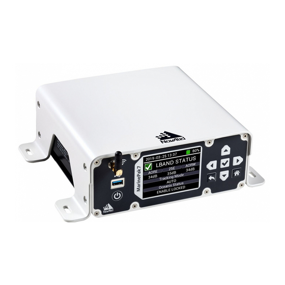
Chapter 3 Configure the MarinePak7 Using the LCD UI This chapter describes how to configure the MarinePak7 and monitor receiver status using the LCD User Interface (LCD UI). 3.1 LCD User Interface The MarinePak7 LCD UI consists of an LCD screen and several navigation buttons. Figure 5: MarinePak7 UI Screen Table 3: MarinePak7 UI Navigation Buttons Keypad Button... -
Page 27: Position Status
Chapter 3 Configure the MarinePak7 Using the LCD UI Keypad Button Description Press from a status screen to access the configuration screen. Enter Button Press to access a configuration sub-level parameter. (Applicable screen only) Press to apply and save settings to the receiver. Home Button Press from any screen to return to the Position Status (Home) screen. -
Page 28: Table 4: Solution Status
Chapter 3 Configure the MarinePak7 Using the LCD UI Table 4: Solution Status Status Description SOL_COMPUTED Solution computed INSUFFICIENT_ Insufficient observations No convergence CONVERGENCE SINGULARITY Singularity at parameters matrix COV_TRACE Covariance trace exceeds maximum (trace > 1000 m) TEST_DIST Test distance exceeded (maximum of 3 rejections if distance >10 km) COLD_START Not yet converged from cold start V_H_LIMIT... -
Page 29: Table 5: Position Type
Chapter 3 Configure the MarinePak7 Using the LCD UI Table 5: Position Type Mode Description NONE No solution FIXEDPOS Position has been fixed by the user entering the position or by position averaging. FIXEDHEIGHT Height has been constrained by the user entered height. DOPPLER_ Velocity computed using instantaneous Doppler VELOCITY... -
Page 30: Position Configuration
Chapter 3 Configure the MarinePak7 Using the LCD UI Mode Description INS position, where the last applied position update used a fixed integer ambiguity INS_RTKFIXED RTK (L1_INT, WIDE_INT or NARROW_INT) solution PPP_ Converging Oceanix solution CONVERGING Converged Oceanix solution OPERATIONAL Solution accuracy is within UAL operational limit WARNING Solution accuracy is outside UAL operational limit but within warning limit... -
Page 31: Base Station Configuration
Chapter 3 Configure the MarinePak7 Using the LCD UI Enable the GSM module and cellular corrections (subscription required) (Receive only). NCOM Enable the MarinePak7 NCOM port. Only one module (MSK, UHF, GSM or NCOM) can be enabled at once. The other unused modules are placed into a low power state to reduce power consumption. -
Page 32: Heading Status
Chapter 3 Configure the MarinePak7 Using the LCD UI Press the Up and Down buttons on the keypad to move between configuration settings. Move to the parameter that is to be configured and press the Enter button to enable EDIT MODE<>. Use the arrow buttons to change the configuration. -
Page 33: Heading Configuration
Chapter 3 Configure the MarinePak7 Using the LCD UI To access the Heading Status screen, press the Right button from the Position Status (Home) screen. Heading Status Indicator Displays GREEN when a Heading solution has been computed. Displays RED if there is no valid Heading solution. Heading Heading in degrees (0°... -
Page 34: Ins Status
Chapter 3 Configure the MarinePak7 Using the LCD UI 3.4 INS Status The INS Status screen provides information about the INS (SPAN) solution. The INS screen is only visible when the MarinePak7 is loaded with a SPAN firmware model. The INS Status and INS CONFIG screens are not visible when the MarinePak7 is in Base Station mode. -
Page 35: Ins Configuration
Chapter 3 Configure the MarinePak7 Using the LCD UI In a typical vessel installation, azimuth represents vessel heading, pitch represents vessel pitch and roll represents vessel pitch. 3.4.1 INS Configuration From the INS Status screen, press the Enter button to access the INS Config screen. Use the Up and Down buttons to select the INS configuration option. -
Page 36: Gnss Status
Chapter 3 Configure the MarinePak7 Using the LCD UI Offset X Axis Y Axis Z Axis X rotation offset Y rotation offset Z rotation offset Rotation from the IMU body from IMU origin from IMU origin from IMU origin frame to the vessel frame. -180 to +180 (deg) -180 to +180 (deg) -180 to +180 (deg) -
Page 37: Gnss Configuration
Chapter 3 Configure the MarinePak7 Using the LCD UI #BDS The number of BeiDou satellites being tracked. #GAL The number of Galileo satellites being tracked. HDOP The real-time Horizontal Dilution of Precision value. PDOP The real-time Position Dilution of Precision value. VDOP The real-time Vertical Dilution of Precision value. -
Page 38: Lband Status
Chapter 3 Configure the MarinePak7 Using the LCD UI Press the Enter button to accept setting changes. To return to the GNSS Status screen, press the Back button. To return to the Position Status screen, press the Home button. 3.6 LBAND Status The LBAND Status and LBAND Configuration screens are not visible when the MarinePak7 is in Base Station mode. -
Page 39: Lband Configuration
Chapter 3 Configure the MarinePak7 Using the LCD UI Tracking Displays the current tracking mode. Mode AUTO – The receiver searches for multiple L-band beams on the L-band channels. MANUAL – The receiver assigns the specified beam on the first L-band channel and makes the other L-band channels IDLE. Oceanix Displays the status of the Oceanix subscription. -
Page 40: Table 6: L-Band Satellites
Chapter 3 Configure the MarinePak7 Using the LCD UI AUTO The receiver searches for multiple L-band beams on the L-band channels based on AUTO selection criteria. If the receiver position is known, the AUTO selection criteria is a ranking of granted access L-band beams by descending elevation angle. -
Page 41: Msk Status
Chapter 3 Configure the MarinePak7 Using the LCD UI 3.7 MSK Status The MSK Status and MSK Configuration screens are not visible when the MarinePak7 is in Base Station mode. You must change the MarinePak7 mode to Rover on the System Configuration screen (see System Configuration on page 57) to access MSK screens. -
Page 42: Msk Configuration
Chapter 3 Configure the MarinePak7 Using the LCD UI 3.7.1 MSK Configuration From the MSK Status screen, press the Enter button to access the MSK Config screen. Use the Up and Down buttons to select the MSK configuration option. Move to the parameter that is to be configured and press the Enter button to enable EDIT MODE<>. -
Page 43: Uhf Configuration
Chapter 3 Configure the MarinePak7 Using the LCD UI The UHF Status and UHF Configuration screens are not visible when the MarinePak7 is in Base Station mode. You must change the MarinePak7 mode to Rover on the System Configuration screen (see System Configuration on page 57) to access UHF screens. To enable the UHF module, the correction source (Correction Src) must be set to UHF on the Position Configuration screen (see Position Configuration on page 30). - Page 44 Chapter 3 Configure the MarinePak7 Using the LCD UI Use the Up and Down buttons to navigate between the configuration options. Move to the parameter that is to be configured and press the Enter button to enable EDIT MODE<>. Use the arrow buttons to change the configuration.
-
Page 45: Gsm Status
Chapter 3 Configure the MarinePak7 Using the LCD UI Compatibility Link Rate (bps), Protocol Modulation Mode Channel Spacing (kHz) PacCrest GMSK 9600,25.0 PacCrest 4FSK 19200,25.0 PacCrest 4FSK 19200,25.0 PacCrest FST 4FSK 19200,25.0 PacCrest FST 4FSK 19200,25.0 Trimtalk GMSK 9600,25.0 Trimtalk GMSK 16000,12.5 Satel 3AS 4FSK 19200,25.0... -
Page 46: Serial Status
Chapter 3 Configure the MarinePak7 Using the LCD UI To access the GSM Status screen from the Home screen, press the Right button until the GSM Status screen displays. For MarinePak7 models without the UHF module, the GSM Status screen follows the MSK Status screen. - Page 47 Chapter 3 Configure the MarinePak7 Using the LCD UI To access the Serial Status screen from the Home screen, press the Right button until the Serial Status screen displays. For MarinePak7 models without the UHF module, the GSM Status screen follows the MSK Status screen.
-
Page 48: Serial Configuration
Chapter 3 Configure the MarinePak7 Using the LCD UI 3.10.1 Serial Configuration From the Serial Status screen, press the Enter button to access the Serial configuration screen. Use the Up and Down buttons to navigate between the configuration options. Move to the parameter that is to be configured and press the Enter button to enable EDIT MODE<>. - Page 49 Chapter 3 Configure the MarinePak7 Using the LCD UI Receive or Transmit Protocol Use the Left or Right button to select the required receive or transmit protocol. Receiver Description Protocols Protocols Mode Base and NONE NONE Disables transmit and receive on the port. Rover –...
- Page 50 Chapter 3 Configure the MarinePak7 Using the LCD UI Pseudorange Measurement Noise Statistics GPS Satellites in View NMEA Heading Log (ALIGN) GPS Specific Information Track Made Good and Ground Speed UTC Time and Date When an NMEA message is selected, a message output frequency option is displayed next to the message.
-
Page 51: Net Port Status
Chapter 3 Configure the MarinePak7 Using the LCD UI 3.11 Net Port Status The Net Port Status screen displays the status of the network port (ICOM port) the receiver uses to communicate through the Ethernet connection. To access the Network Status screen from the Home screen, press the Right button until the Net Port Status screen displays. - Page 52 Chapter 3 Configure the MarinePak7 Using the LCD UI Use the Up and Down buttons to navigate between the configuration options. Move to the parameter that is to be configured and press the Enter button to enable EDIT MODE<>. Use the arrow buttons to change the configuration.
- Page 53 Chapter 3 Configure the MarinePak7 Using the LCD UI When NMEA is highlighted, press the Enter button to access the NMEA message selection option. Use the Left or Right button to scroll through the NMEA messages available. Select the required message and press the Enter button to access message output rate options.
-
Page 54: Network Status
Chapter 3 Configure the MarinePak7 Using the LCD UI After all the configuration options have been set, press the Enter button to accept the changes and save the settings to the receiver. Press the Back button to return to the Net Port Status screen. Press the HOME button to return to the Position Status screen. - Page 55 Chapter 3 Configure the MarinePak7 Using the LCD UI Use the Up and Down buttons to navigate between the configuration options. Move to the parameter that is to be configured and press the Enter button to enable EDIT MODE<>. Use the arrow buttons to change the configuration.
-
Page 56: System Status
Chapter 3 Configure the MarinePak7 Using the LCD UI After all the configuration options have been set, press the Enter button to accept the changes and save the settings to the receiver. Press the Back button to return to the Network Status screen. Press the HOME button to return to the Position Status screen. -
Page 57: System Configuration
Chapter 3 Configure the MarinePak7 Using the LCD UI 3.13.1 System Configuration From the System Status screen, press the Enter button to access the System configuration screen. Use the Up and Down buttons to navigate between the configuration options. Move to the parameter that is to be configured and press the Enter button to enable EDIT MODE<>. - Page 58 Chapter 3 Configure the MarinePak7 Using the LCD UI 3. Press the Left or Right button to make a selection. Enables antenna power to the GNSS2 port. This port connects to the secondary GNSS antenna. Disables power to the GNSS2 port. 4.
-
Page 59: System Information
Chapter 3 Configure the MarinePak7 Using the LCD UI Solution Type Description Mode NARROW_INT NARROW_INT is achieved when compatible and valid RTK ROVER SINGLE corrections are received. FIX position solution is achieved when the base station coordinates are input into the Base Station Configuration on page 31 screen. BASE FIXEDPOS The correction source, type and baud rate must first be... - Page 60 Chapter 3 Configure the MarinePak7 Using the LCD UI To access the System Information screen from the Home screen, press the Right button until the System Info screen displays. For MarinePak7 models without the UHF module, the GSM Status screen follows the MSK Status screen.
-
Page 61: Chapter 4 Web User Interface
Chapter 4 Web User Interface The Web User Interface (Web UI) provides access to the MarinePak7 via a WiFi connection. Once communication has been established with the receiver, the NovAtel Web UI can be opened using a web browser. 4.1 Open the Web UI Once the MarinePak7 is connected and powered, use a WiFi capable device to locate the MarinePak7 in the list of detected WiFi Networks and establish a connection. -
Page 62: Dashboard
Chapter 4 Web User Interface 4.3 Dashboard The tiles on the Dashboard provide an overview of the receiver operational status. 4.3.1 General Status Tile Provides the GNSS and logging status. GNSS Displays green when the receiver is tracking more than 4 healthy satellites. Displays red when the receiver is tracking less than 4 healthy satellites. -
Page 63: Module Status Tile
Chapter 4 Web User Interface 4.3.2 Module Status Tile Provides the status of the radio frequency modules in the MarinePak7. Only one radio frequency module can be activated at a time. Displays green when the UHF module is active and locked onto a UHF channel. Displays red when the UHF module is not active. -
Page 64: Position Status Tile
Chapter 4 Web User Interface GNSS Status A green circle in the top right corner indicates GNSS tracking is healthy. A red circle is a warning that satellite tracking has fallen below the minimum required to obtain a computed solution (SOL_COMPUTED). GPS Satellites Number of GPS satellites used in the solution. -
Page 65: Ins Status Tile
Chapter 4 Web User Interface Position Status A green circle in the top right corner indicates a position is being generated and a valid solution is computed (SOL_COMPUTED). A red circle indicates a solution status other than SOL_COMPUTED is reported from the receiver. -
Page 66: Heading Status Tile
Chapter 4 Web User Interface INS Status A green circle in the top right corner indicates a SPAN solution has been computed. A red circle indicates a valid SPAN solution is not available. Roll Roll of the vessel. Pitch Pitch of the vessel. Azimuth Heading of the vessel. -
Page 67: Receiver Configurable Parameters Tile
Chapter 4 Web User Interface Serial Number Serial number of GNSS receiver board inside the MarinePak7. Firmware Version Firmware version of the GNSS receiver board. H/W Version Hardware version of the GNSS receiver board in the format: Where P = hardware platform R = hardware revision Example: OEM7720-1.01 Model... -
Page 68: Rtk Tile
Chapter 4 Web User Interface To configure the receiver parameters: 1. From the Correction Source drop-down menu, select the source. Enable the MSK DGPS receiver module and RTCM correction format (Receive only). Enable the Satel UHF radio module (Receive only). Enable the GSM module and cellular corrections (subscription required) (Receive only). - Page 69 Chapter 4 Web User Interface When the MarinePak7 is enabled as an RTK Base, the Base Station latitude, longitude and height coordinates are displayed, RTK correction output is enabled and the Position Status mode is set to FIXEDPOS. To configure the MarinePak7 as an RTK Rover (receive RTK corrections): 1.
-
Page 70: Ins Tile
Chapter 4 Web User Interface 3. In the Latitude field, enter the latitude of the MarinePak7. The value range for the latitude is -90 to +90 (degrees). 4. In the Longitude field, enter the longitude of the MarinePak7. The value range for the longitude is -180 to +180 (degrees). - Page 71 Chapter 4 Web User Interface Click the Edit icon ( ) to enter the configuration window. To configure the INS parameters: 1. In the Lever Arm 1 text boxes, enter the offsets from the IMU center of navigation to the phase center of the primary GNSS antenna.
-
Page 72: Heading Offset Tile
Chapter 4 Web User Interface The second box is the Y-axis offset from the IMU to the primary GNSS antenna. The third box is the Z-axis offset from the IMU to the primary GNSS antenna. 2. In the Lever Arm 2 text boxes, enter the offsets from the IMU center of navigation to the phase center of the secondary GNSS antenna. -
Page 73: Pps Tile
Chapter 4 Web User Interface 1. In the Offset field, enter the angular offset to be added to heading output. The range is -180 to +180 (degrees). 2. Click the Save changes button. 4.4.10 PPS Tile The PPS tile displays the polarity setting for the PPS signal. Click the Edit icon ( ) to enter the configuration window. -
Page 74: Ethernet Tile
Chapter 4 Web User Interface 1. From the Polarity drop-down menu, select the polarity of the pulse generated on the PPS output. Disables the PPS output. NEGATIVE Set the polarity of the PPS pulse to negative. (default = NEGATIVE) Generates a normally high, active low pulse with the falling edge as the reference. -
Page 75: Ntrip Tile
Chapter 4 Web User Interface The IP, Subnet Mask and Gateway parameters are editable only when DHCP is set to OFF. 1. In the IP box, enter the IP address for the MarinePak7. 2. In the Subnet Mask box, enter the subnet for the MarinePak7. 3. -
Page 76: L-Band
Chapter 4 Web User Interface Click the Edit icon ( ) to open the configuration options window. 1. In the IP box, enter the IP address of the NTRIP service. 2. In the IP_port box, enter the IP port of the NTRIP service. 3. -
Page 77: L-Band Details Tile
Chapter 4 Web User Interface Oceanix Displays ENABLE when there is a valid Oceanix subscription and the receiver has successfully Status locked onto at least 1 beam. Displays DISABLE if there is no valid Oceanix subscription or the receiver has failed to lock onto at least 1 beam. - Page 78 Chapter 4 Web User Interface To change the Oceanix configuration, click the Edit icon ( ) to enter the configuration menus. 1. Click the Tracking Mode drop menu and select the mode. Auto The receiver searches for multiple L-band beams on the L-band channels. If the receiver position is known, the AUTO selection criteria is a ranking of granted access L-band beams by descending elevation angle.
-
Page 79: Uhf Radio
Chapter 4 Web User Interface 4.6 UHF Radio The UHF Radio page displays information about the UHF radio. 4.6.1 UHF Radio Status Tile This tile provides status information about the UHF radio Status A green circle in the top right indicates the UHF module is active and locked onto a UHF channel. - Page 80 Chapter 4 Web User Interface Click the Edit icon ( ) to open the configuration options window. 1. Click the Mode drop menu and select Rx to set the UHF radio to receive mode. 2. Click the Compatibility drop menu and select the radio compatibility mode. See the compatibility mode descriptions in the following table.
-
Page 81: Msk Beacon
Chapter 4 Web User Interface Compatibility Link Rate (bps), Protocol Modulation Mode Channel Spacing (kHz) PacCrest FST 4FSK 9600,12.5 PacCrest FST 4FSK 9600,12.5 Trimtalk GMSK 4800,12.5 Trimtalk GMSK 8000,12.5 Satel 3AS 4FSK 9600,12.5 Satel 3AS 4FSK 9600,12.5 PacCrest GMSK 9600,25.0 PacCrest GMSK 9600,25.0 PacCrest 4FSK... -
Page 82: Msk Beacon Configuration Tile
Chapter 4 Web User Interface Status A green circle in the top right corner indicates the MSK module is active and locked onto a valid correction source. Displays red when the MSK module is not active or not locked onto a valid correction source. Signal The Signal to Noise Ratio of the signal being received by the MSK module. -
Page 83: Serial Ports
Chapter 4 Web User Interface Mode Auto Automatically searches and uses the highest quality MSK beacon data stream. Manual Manually select the MSK transmission frequency. Frequency 283.5 - 325.0 Enter the MSK transmission frequency. (Manual Mode only.) 4.8 Serial Ports The Serial Ports page displays the serial port configuration and the logs configured to be output from the selected serial ports. - Page 84 Chapter 4 Web User Interface See Table 7: I/O Parameters on the next Select the Rx/Tx protocol used for this COM page port. Line RS232 Use RS232 protocol on this COM port. Standard RS422 Use RS422 protocol on this COM port. Baud rate 2400, 4800, 9600, 19200, 38400, Select the baud rate used on this COM port.
-
Page 85: Log List Tile
Chapter 4 Web User Interface Table 7: I/O Parameters Receiver Description Protocols Protocols Mode Base and None None Disables transmit and receive on the port. Rover – NMEA OUT Rover Outputs NMEA messages – CMR OUT Base Outputs CMR correction messages RTCMV3 –... - Page 86 Chapter 4 Web User Interface To add a log to output, click the Add icon ( ) to open the Add Log Configuration window. To modify a log being output, click the Edit icon ( ) to open the Edit Log Configuration window. MarinePak7 User Manual 2...
-
Page 87: Table 8: Nmea Message Ids
Chapter 4 Web User Interface To remove a log from the Log List, click the Delete icon ( Port Name COM1, Select the COM port from which the log is output. COM2, The COM port cannot be changed from the Edit Log Configuration window. COM3 Message Message ID... -
Page 88: Net Ports
Chapter 4 Web User Interface NMEA Messages Description UTC Time and Date Estimated Error in Position Solution Heading GNSS DOP on Active Satellites GNSS Satellites in View GNSS Range Residuals for Each Satellite GNSS Specific Information Table 9: INS Message IDs INS Message Description SPAN Heave message... -
Page 89: Net Ports Log List Tile
Chapter 4 Web User Interface 1. Click the Protocol drop menu and select the protocol used for this ICOM port. Use TCP Use UDP 2. The Port box displays the port number assigned to the ICOM port. 3. Click the I/O drop menu and select the message protocol used for this ICOM port. NMEA OUT Output NMEA message types. - Page 90 Chapter 4 Web User Interface To add a log to output, click the Add icon ( ) to open the Add Log Configuration window. To modify a log being output, click the Edit icon ( ) to open the Edit Log Configuration window. To remove a log from the Log List, click the Delete icon ( MarinePak7 User Manual 2...
-
Page 91: Logging
Chapter 4 Web User Interface Port Name ICOM1, If adding a log to an ICOM port, select the ICOM port to configure. ICOM2, If editing, this field displays the name of the ICOM port. ICOM3 Message Message ID Select the Message ID of the log to be output on this COM port. of the log The logs can be NMEA or INS logs. -
Page 92: Disk Usage
Chapter 4 Web User Interface 4.10.3 Disk Usage This tile provides a graphic representation of the percentage of disk space used. 4.10.4 Log Actions Use this tile to download the logs stored on internal data storage or delete stored logs from internal data storage. -
Page 93: Log List
Chapter 4 Web User Interface 4. Click the Download button. The default location the file is downloaded to is OS (C:)\Users\[user]\Downloads. To delete the stored logs: 1. Click the Delete User Log button. The Select Log File to Delete window appears. 2. - Page 94 Chapter 4 Web User Interface To modify a log being saved to internal storage, click the Edit icon ( ) for the log to change to open the Edit Log Configuration window. To remove a log from the Log List, click the Delete icon ( MarinePak7 User Manual 2...
-
Page 95: System
Chapter 4 Web User Interface Message Message ID of the log Select the Message ID of the log to be output on this COM port. The logs can be NMEA standard or NovAtel logs. For the list of the logs available, see docs.novatel.com/OEM7/Content/Logs/OEM7_ Core_Logs.htm. -
Page 96: Antenna Ant1
Chapter 4 Web User Interface To enable WiFi, set the WiFi switch to On. To disable WiFi, set the WiFi switch to Off. To edit the WiFi password and country of origin: 1. Click the Edit icon ( ). The Edit Wifi Configuration window appears. 2. -
Page 97: Gsm
Chapter 4 Web User Interface 4.11.5 GSM The GSM tile provides information about the GSM (cellular) radio. Status Displays On when the GSM cellular modem is active. Display Off when the GSM cellular modem is not active. Signal Strength Displays the signal strength of the cellular reception. Mode Displays the cellular connection mode. -
Page 98: Firmware
Chapter 4 Web User Interface 2. Use the slider to set the LCD screen brightness. 3. Click the Save changes button. 4.11.7 Firmware The Firmware tile displays the current firmware version installed on the MarinePak7 and can be used to update the firmware. - Page 99 Chapter 4 Web User Interface 6. Click the Open button. 7. Click the Install button. Once the upload is complete, the MarinePak7 will restart. MarinePak7 User Manual 2...
-
Page 100: Appendix A Marinepak7 Technical Specifications
APPENDIX A MarinePak7 Technical Specifications APPENDIX A MarinePak7 Technical Specifications Table 10: MarinePak7 Physical Description 198 mm x 199.5 mm x 80 mm (without shroud) Size 198 mm x 254 mm x 80 mm (with shroud) Weight 3 kg MP7720 NovAtel Part Number MP7720U See the following sections for more information about the MarinePak7:... -
Page 101: Marinepak7 Performance Specifications
APPENDIX A MarinePak7 Technical Specifications A.1 MarinePak7 Performance Specifications All specifications subject to GNSS system characteristics. Table 11: MarinePak7 Receiver Performance Single point L1 1.5 m RMS Single point L1/L2 1.2 m RMS SBAS 60 cm RMS Position Accuracy DGPS 40 cm RMS 3 , 4 Oceanix... - Page 102 APPENDIX A MarinePak7 Technical Specifications L1 C/A, L1C, L2C, L2P, L5 L1 C/A, L2 C/A, L2P, L3, L5 GLONASS Signals Tracked Galileo E1, E5 AltBOC, E5a, E5b Secondary Antenna (GNSS2) BeiDou B1I, B1C, B2I, B2a, B2b NavIC (IRNSS) QZSS L1 C/A, L1C, L2C, L5 Hot: <19 s (almanac and recent ephemeris saved and approximate position and time entered) Time to First Fix...
- Page 103 APPENDIX A MarinePak7 Technical Specifications Code Carrier L1 C/A 4 cm 0.5 mm L2 P(Y) 8 cm 1.0 mm 8 cm 0.5 mm 3 cm 0.5 mm L1 C/A 8 cm 1.0 mm GLONASS L2 P 8 cm 1.0 mm L2 C/A 8 cm 1.0 mm...
-
Page 104: Marinepak7 Mechanical Specifications
APPENDIX A MarinePak7 Technical Specifications A.2 MarinePak7 Mechanical Specifications Figure 6: MarinePak7 Dimensions – Top below Figure 7: MarinePak7 Dimensions – Front below Figure 8: MarinePak7 Dimensions – Back on the next page Figure 9: MarinePak7 Mounting Shroud Tabs on page 106 Figure 10: MarinePak7 Mounting Holes on page 107 Figure 6: MarinePak7 Dimensions –... -
Page 105: Figure 8: Marinepak7 Dimensions - Back
APPENDIX A MarinePak7 Technical Specifications Figure 8: MarinePak7 Dimensions – Back MarinePak7 User Manual 2... -
Page 106: Figure 9: Marinepak7 Mounting Shroud Tabs
APPENDIX A MarinePak7 Technical Specifications Figure 9: MarinePak7 Mounting Shroud Tabs MarinePak7 User Manual 2... -
Page 107: Figure 10: Marinepak7 Mounting Holes
APPENDIX A MarinePak7 Technical Specifications Figure 10: MarinePak7 Mounting Holes MarinePak7 User Manual 2... -
Page 108: Marinepak7 Electrical And Environmental Specifications
APPENDIX A MarinePak7 Technical Specifications A.3 MarinePak7 Electrical and Environmental Specifications Table 12: MarinePak7 Power Requirements Voltage 12 – 24 VDC Minimum Typical 12 W Power Consumption Maximum 36 W (In Charge State) Table 13: Battery Specifications Manufacturer Inspired Energy Part number ND2037HD34 Type... -
Page 109: Table 15: Marinepak7 Regulatory Compliance
APPENDIX A MarinePak7 Technical Specifications Humidity 95% non-condensing Waterproof IEC 60529 IPX7 Dust IEC 60529 IP6X Vibration (operating) IEC 60945 Table 15: MarinePak7 Regulatory Compliance Compliance FCC, CE, IEC 60945 (Protected), AZ/NSZ Table 16: MarinePak7 RF Input/LNA Power Output Antenna Connectors TNC female, 50 Ω... -
Page 110: Marinepak7 Data Communications Specifications
APPENDIX A MarinePak7 Technical Specifications A.4 MarinePak7 Data Communications Specifications Table 17: Data Communications Interfaces COM1 Electrical format RS-232/RS-422 2400, 4800, 9600, 19200, 38400, 57600, 115200, 230400 or 460800 bit/s Data rates Default = 9600 COM1_Tx, COM1_Rx, COM1_RTS, COM1_CTS (RS-232) Signals supported COM1_Tx+, COM1_Tx-, COM1_Rx+, COM1_Rx- (RS-422) Port... - Page 111 APPENDIX A MarinePak7 Technical Specifications Data rates Hi-speed (480 Mb/s) Port USB Type A ETHERNET Physical layer 10BASE-T/100BASE-TX Port RJ45 WiFi WiFi module Texas Instruments WL1835MOD Band 2400 MHz Transmission power 0.0549 W (max) Security WPA2 Encryption Port SMA 50Ω MarinePak7 User Manual 2...
-
Page 112: Marinepak7 Strobe Specifications
APPENDIX A MarinePak7 Technical Specifications A.5 MarinePak7 Strobe Specifications The MarinePak7 strobe signals are available on the I/O connector and COM ports. Table 18: MarinePak7 Strobes Description Factory Strobes Input/Output Comment Default Input marks for which a pulse greater than 150 ns triggers certain logs to be generated. -
Page 113: Msk Beacon Receiver Specifications
APPENDIX A MarinePak7 Technical Specifications A.6 MSK Beacon Receiver Specifications Table 20: Receiver Module Channels 2-channel parallel tracking Frequency range 283.5 to 325.0 kHz Channel spacing 500 Hz Demodulation Minimum Shift Keying (MSK) MSK bit rates 50, 100 and 200 bps Cold start time <... -
Page 114: Uhf Radio Specifications
APPENDIX A MarinePak7 Technical Specifications A.8 UHF Radio Specifications The UHF radio module is a Satel TR49. Table 22: Transceiver Module UHF module SATEL TR49 Band 410 – 475 MHz Transmission power (max) UHF module SATEL TR49 Band 902 – 928 MHz Transmission power (max) Modulation... -
Page 115: Table 24: Com2 Pinout
APPENDIX A MarinePak7 Technical Specifications RS-232 RS-422 Signal Name Description Signal Name Description Transmit data – Transmit data TxD+ positive No connection No connection Signal ground Signal ground No connection No connection Transmit data – Request to Send TxD- negative Receive data – Clear to Send RxD- negative... -
Page 116: Dc Power Port
APPENDIX A MarinePak7 Technical Specifications Table 25: COM3 Pinout RS-232 RS-422 Signal Name Description Signal Name Description Programmable Programmable variable variable frequency EVENTOUT3 frequency output ranging EVENTOUT3 output ranging from from 0 Hz to 50 MHz 0 Hz to 50 MHz Receive data – Receive data RxD+ positive... -
Page 117: I/O Port
APPENDIX A MarinePak7 Technical Specifications A.9.3 I/O Port Table 27: I/O Pinout Signal Name Description Reserved Reserved Reserved Reserved Signal ground Reserved Reserved Reserved Reserved Signal ground EVENTOUT4 Programmable variable frequency output ranging from 0 Hz to 50 MHz Input mark for which a pulse greater than 150 ns triggers certain logs to be EVENTIN1 generated Reserved... -
Page 118: Serial Data Cable
APPENDIX A MarinePak7 Technical Specifications A.10 Serial Data Cable This cable connects a device with a DB9 serial port, such as a computer, to the COM1, COM2 or COM3 port on the MarinePak7. Figure 11: Serial Data Cable Table 28: Serial Data Cable Pinout DB9 (J1) DB9 (J2) 1 &... -
Page 119: Power Supply
APPENDIX A MarinePak7 Technical Specifications A.11 Power Supply The Power Supply connects the MarinePak7 to the mains supply. The connector on the mains supply side of the Power Supply varies depending on the region in which the Power Supply is intended to be used. -
Page 120: Dc Power Cable
APPENDIX A MarinePak7 Technical Specifications A.12 DC Power Cable This cable connects the MarinePak7 to a DC power supply. Figure 13: DC Power Cable Table 29: DC Power Cable Pinout Connector A Pin Signal Name Flying Lead Wire Color Power Black Power Blue... - Page 121 MarinePak7 User Manual 2...
Need help?
Do you have a question about the NovAtel MarinePak7 and is the answer not in the manual?
Questions and answers