Hexagon veripos LD900 Installation And Operation Manual
Hide thumbs
Also See for veripos LD900:
- Commissioning manual (25 pages) ,
- Installation and operation manual (106 pages)
Table of Contents
Advertisement
Advertisement
Table of Contents

Subscribe to Our Youtube Channel
Related Manuals for Hexagon veripos LD900


Summary of Contents for Hexagon veripos LD900
- Page 1 LD900 Installation and Operations Manual AB-V-MA-00643_RevA3 26 February 2021...
- Page 2 Contents Contents Contents ............................2 Introduction ..........................4 General Information..............................4 LD900 Receiver ................................4 VERIPOS Support ..............................5 Activating VERIPOS Correction Services ....................... 5 Terms and Abbreviations............................6 Document Conventions.............................. 8 LD900 Notices................................9 Disclaimer ..................................12 Equipment Care ................................13 Hardware Overview .........................14 System Overview ..............................14 Hardware Models..............................14...
- Page 3 Contents L-band Signal Issues..............................58 GNSS Signal Issues..............................58 Corrections Issues ..............................59 GNSS Heading Issues .............................59 INS Issues..................................60 Reference Information ......................61 Technical Specifications ............................61 Cabling and Connectors ............................63 Veripos H70 PC Specifications..........................65 LD900 Output Sentences ............................66 Contact Information.........................80 VERIPOS Helpdesk Details ............................80 Appendix ..........................81 Summary Specification of Antennas ........................81 Summary Specification of Cabling .........................83...
-
Page 4: General Information
19 Inch Rack Mount options (for single or dual LD900 systems) 1.2.1 Preamble The purpose of this manual is to provide the information necessary to install and operate the VERIPOS LD900. Read this manual in conjunction with the Delivery note provided for your installation. - Page 5 Introduction 1.3 VERIPOS Support Throughout this manual, references are made to the VERIPOS Helpdesk. The Helpdesk is a service provided as the f irst point of contact for all VERIPOS technical support and fault reports. It is manned 24 hours a day, 365 days per year.
-
Page 6: Terms And Abbreviations
Introduction 1.5 Terms and Abbreviations Alternating Current APEX VERIPOS high accuracy positioning solution Antenna Ref erence Point American Wire Gauge BEIDOU Chinese commissioned GNSS A bayonet type of RF coaxial connector Computed Minus Observed Centimetre Decibel dBuV Decibel (microVolts) Direct Current DGNSS Dif ferential GNSS DGPS... - Page 7 Introduction Radio Frequency RJ45 A physical network interface standard used in telecommunications RTCM Radio Technical Commission for Maritime Services Real-time Kinematic Seconds Serial Access License SAL M12 Sensor Actor Line SBAS Satellite Based Augmentation System Standard VERIPOS Single frequency DGPS system Space Vehicle Transmission Control Protocol A threaded type of RF coaxial connector...
-
Page 8: Document Conventions
Introduction 1.6 Document Conventions 1.6.1 Typographical Conventions Italic or bold text is used to emphasize certain information. Italic is also used in cross-references to other parts of the document and to other documents. Bold text is also used for indicators and touch screen “push-buttons” commands. Blue text is used for hyperlinking to other sections within this document or to external documents or websites. - Page 9 Introduction 1.7 LD900 Notices The f ollowing notices apply to the LD900: 1.7.1 Waste Electrical and Electronic Equipment The Waste Electrical and Electronic Equipment Directive (hereinafter referred to as the “WEEE directive”) places an obligation on EU-based manufacturers, distributors, retailers and importers to take-back electronics products at the end of their useful life.
- Page 10 Introduction 1.7.2 FCC This device complies with part 15 of the FCC Rules. Operation is subject to the following two conditions: (1) this device may not cause harmful interference, and (2) this device must accept any interference received, including interf erence that may cause undesired operation. LD900 has been tested and found to comply with the radiated and conducted emission limits for a Class B digital device.
- Page 11 Introduction 1.7.3 European Union 1.7.3.1 Radio Equipment Directive VERIPOS declares that the LD900 including its Wi-Fi transceiver is in compliance with Directive 2014/53/EU (Radio Equipment). Radio Inf ormation: Description of Service: Wi-Fi (802.11b/g/n) Operational Frequency: 2412 MHz to 2462 MHz Modulation: OFDM Rated Power: 16.38dBm The f ull text of the EU Declaration of Conformity may be obtained from VERIPOS upon request.
- Page 12 VERIPOS Limited and/or its licensors. All other marks used herein are trademarks of their respective holders. All other marks used herein are trademarks of their respective holders. Veripos Limited is part of the Hexagon Autonomy and Positioning division of companies of Hexagon AB. LD900 Installation and Operations Manual...
-
Page 13: Equipment Care
Introduction 1.9 Equipment Care 1.9.1 Unpacking and Inspection Caref ully unpack and inspect the unit. If the equipment appears damaged, contact VERIPOS for further advice ensuring to retain the original packaging. Responsibility for damage will not be accepted if approved packaging is not used. -
Page 14: Hardware Overview
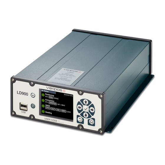
Hardware Overview 2 Hardware Overview This section provides an overview of the VERIPOS LD900 receiver and det ails the physical characteristics of the system and the different models. 2.1 System Overview The LD900 is a high precision system, built into a rugged enclosure and designed to operate reliably in the most demanding of marine environments. -
Page 15: Interface And Connectors
Hardware Overview 2.3 Interface and Connectors The LD900 f eatures a 3.5” colour MMI with keys to navigate the UI, allowing for user configuration and status monitoring. 2.3.1 Front Panel Interface The LD900 f ront panel provides a display UI, controls and USB 2.0 port for system updates and data archiving: 2.3.2 Rear Panel Connectors The LD900 rear panel has several RF and data connectors for interfacing with the unit: Label... - Page 16 Hardware Overview 2.3.2.1 Serial Ports The LD900 has three serial ports: COM1, COM2 and COM3, accessible via 9 pin D-Type connectors and a 15- pin D-Type AUX serial port. Refer to the Cabling and Connectors section for more details. Galvanically Flow Port RS-232...
- Page 17 Hardware Overview CAUTION If the voltage supplied is below the minimum specification, the receiver will automatically shut down. If the voltage supplied is above the maximum specification, the receiver may be permanently damaged and void the warranty. The supply must be capable of providing enough current to operate the LD900. WARNING To ensure safety, only limited power source AC/DC adapters supplied by VERIPOS should be used with the product.
-
Page 18: Schematic Examples
LD900 Installation 3 LD900 Installation This section provides guidance on the installation of the LD900 receiver. In the event of difficulty, contact your supplier or VERIPOS (support@veripos.com). CAUTION The personnel responsible for installing the LD900 system must be properly trained and competent to install electronic equipment. - Page 19 LD900 Installation 3.1.2 Survey Installation (LD900 Model) Heading Option Independent L-band Option LD900 Installation and Operations Manual...
- Page 20 LD900 Installation 3.1.3 DP Installation (LD900M Model) Heading Option LD900 Installation and Operations Manual...
- Page 21 LD900 Installation 3.2 Rack Mount Formats The LD900 can be supplied in one of two rack-mountable formats. The single format integrates a single LD900 with optional extras and easy access to configurable ports, while the dual format provides two LD900s within a single enclosure.
- Page 22 LD900 Installation The single f ormat rack mount system has many of the internal interconnections preinstalled, with the remaining connections to be finalised at installation: Connection Prewired? LD900 Antenna/s (L-band, GNSS, MF) LD900 1PPS LD900 COM Ports (1-3) LD900 LAN Ports LD900 UHF Receiver Data LD900 DC Power Moxa DC Power...
- Page 23 LD900 Installation 3.2.4 LD900 and VERIPOS PC – Network Bridge Setup Once the Ethernet connections have been established, the PC ports will need to be bridged together. Within Windows, on the VERIPOS PC, go to Start, type Ethernet Settings and press Enter. In the window that opens, under Related settings, select Change adapter options.
- Page 24 LD900 Installation 3.3 LD900 Location Guidelines When choosing installation locations, the following requirements should be taken into consideration: • Ensure adequate ventilation for free airflow to the main unit. This is especially important when working in hot or humid conditions. See section Ventilation Requirements for more details.
-
Page 25: Ventilation Requirements
LD900 Installation 3.5 Ventilation Requirements The LD900 needs 15-25mm minimum clearance all-round to allow a f low of air: 15-25mm 15-25mm 15-25mm 3.6 Antenna Installation This section provides general guidance on the installation of antennas and cabling when installing the LD900 receiver. - Page 26 LD900 Installation 3.6.2 LD900 Models and Coaxial Connections The below table lists the LD900 models and which antenna is required to be connected to each connector: ‘LBAND’ TNC* ‘GNSS1’ TNC ‘GNSS2’ TNC** ‘BEACON’ TNC Model Name LD900L (L-band) LD900 (L-band & GNSS) V560 V560 LD900M (L-band, GNSS &...
- Page 27 LD900 Installation • A mounting pole can be used with a 5/8"x11 UNC threaded end (standard marine mount). The pole can be attached by welding, or by using “U” clamps. This method allows the antenna to be mounted without the need f or a bracket. •...
-
Page 28: Cable Installation
LD900 Installation GNSS2 Vessel Heading GNSS1 NOTE The antenna orientation examples are simplified for illustration purposes. To achieve an accurate vessel heading a calibration must be conducted. GNSS1 and GNSS2 should also be installed at similar heights to ensure consistent heading. If this is not done, the heading solution will be noisy due to the f act that each antenna will be subject to a dif ferent magnitude of vessel motion (such as vessel roll): 3.6.5 UHF Antenna... - Page 29 LD900 Installation Terminated Tails of LMR240 When running multiple coaxial cables, VERIPOS recommends labelling to ensure cables are attached to the correct antennas and equipment. Survey the route of the antenna cabling to ensure: • The total length of the cable run does not exceed the supplied cable length for this installation. Contact your supplier or VERIPOS if this is not the case.
-
Page 30: Configuration And Operations
Configuration and Operations 4 Configuration and Operations The LD900 can be configured via the front LCD panel and controls, or by using a licensed version of the VERIPOS Quantum software. For inf ormation on configuration with the use of Quantum please see the Quantum User Manual. 4.1 Start-Up Connect power to the rear of the unit. - Page 31 Configuration and Operations NOTE A user can return to the Status page at any time by pressing the Home button. 4.4 Status (LD900L Model) The Status page of the L-band only LD900L model will display beam and signal strength information based on user location, with the Menu page accessible by pressing the front panel tick button: In the example above, traffic light indicators are used to convey three different beam states (red is <32.5dB/Hz, amber is <36.5dB/Hz &...
- Page 32 Configuration and Operations 4.5.1 Status > Positioning Overview 4.5.1.1 Positioning Indicator States = Position corrected = Position uncorrected (or) PPP settling = No active position Positioning mode in use will be highlighted ( PPP = Apex (or) Ultra DGNSS = Standard, MF or SBAS An INS aided position will be highlighted ( 4.5.1.2 Corrections Indicator States...
- Page 33 Configuration and Operations 4.5.1.5 INS Indicator States The INS status is shown only when licensed. Note when INS is authorised the heading will be displayed within the page. = INS converged = INS settling = INS inactive = INS not configured An INS aided position is highlighted ( 4.5.2 Status >...
- Page 34 Configuration and Operations 4.5.3.1 Status > Corrections > RTK The RTK page displays the station ID and the correction age value. 4.5.3.2 Status > Corrections > VERIPOS The VERIPOS page displays following: • Beam - Tracked L-band beam name • Signal Quality - Signal strength in dB/Hz >36.5 <36.5...
- Page 35 Configuration and Operations 4.5.3.5 Status > Corrections > SBAS The SBAS page displays the satellite PRN code and signal strength of the satellite that will be used f or corrections. 4.5.4 Status > GNSS The GNSS page displays the number of both used and tracked satellites for each constellation, the DOP values and the tracking Elevation Mask.
- Page 36 Configuration and Operations 4.6 Configuration The Configuration menu page provides control of system settings. The menu options shown will depend on your particular LD900 model type. Starting with Positioning, this section details the different menu options and the corresponding configuration settings available. 4.6.1 Configuration >...
- Page 37 Configuration and Operations NOTE Changing the PPP Mode will re-initialise the PPP calculation, which will take time to settle before a PPP solution output becomes available. 4.6.1.2 Configuration > Positioning > NMEA Config As part of configuring port outputs users may wish to also define the GGA Precision and PPP DQI values of Sentence.
- Page 38 Configuration and Operations 4.6.1.3 Configuration > Positioning > TRINAV Config As part of configuring port outputs users may wish to also define the TRINAV Version and Nav Point used. Version The Version is set to V3 by default but can be toggled to V4 as required. Nav Point The Nav Point is set to 01 by default but can be set to a value between 01 and 99 as required.
- Page 39 Configuration and Operations Beam The LD900 receiver supports multi-channel L-band tracking, providing reception of services from up to three satellites broadcasting VERIPOS corrections simultaneously. This reduces the risk of satellite masking or blocking and ensures continuous reception of VERIPOS correction services. Auto is the recommended selection, as this will automatically select the three highest elevation L-band beams for your location.
- Page 40 Configuration and Operations Source Antenna The LD900 can be configured to use just combined L-band and GNSS or L-band only antenna. Source Antenna can be set to use the RF connector L-band or GNSS1 by clicking on Edit and using the arrow keys and tick to select L-band or GNSS1 as required, followed by tick.
- Page 41 Configuration and Operations When setting to Manual, the user will be prompted to enter a valid station frequency, between 283.5 and 325.0kHz, which can be added by using the arrow keys followed by tick: 4.6.2.3 Configuration > Corrections > UHF UHF Mode allows the user to select either Off (default) or Manual UHF tracking.
- Page 42 Configuration and Operations 4.6.2.5 Configuration > Corrections > RTK The LD900 is capable of using RTK corrections from a suitable source. RTK Source controls if RTK corrections are used by the system, where corrections are available. This can be set to Off (default) or RTCMV3. For the corrections to be accepted by the receiver they must be provided in RTCMv3 format.
- Page 43 Configuration and Operations 4.6.3 Configuration > GNSS Within the GNSS menu page, changes can be made to the Elevation Mask and the PPS by clicking on the corresponding Edit options: 4.6.3.1 Configuration > GNSS > Elevation Mask The Elevation Mask defines a value, below which satellites will not be tracked. The system is fixed to only use satellites above 7°...
- Page 44 Configuration and Operations 4.6.4 Configuration > Ports LD900 data input and output is available via serial (COM), with TCP/IP socket (ICOM) providing output only. A Moxa serial port expansion unit can be used to convert ICOM to serial (P) where required. NOTE Heading must be licensed and turned on...
- Page 45 Configuration and Operations The Additional Settings options are as follows: • Protocol - RS232 (default) / RS422 • Data Bits - 7 / 8 (def ault) • Parity Bits - N (def ault) / E / O • Stop Bits - 1 (def ault) / 2 Once the desired COM port has been configured, use the arrow buttons and tick to select Next.
- Page 46 Configuration and Operations When selecting Output > NMEA, a choice of GGA, GLL, VTG, ZDA, GST, GSA, GSV, GRS and RMC will be shown, f ollowed by a request to pick an NMEA output rate of 1 (default), 2, 5, 10 or 20Hz. If heading is licensed enabled HDT will also be shown and additionally if INS is licensed PASHR will be shown: Once configured the user will be returned to the Configuration >...
- Page 47 Configuration and Operations If selecting NMEA, a choice of GGA, GLL, VTG, ZDA, GST, GSA, GSV, GRS and RMC will be shown, followed by a request to pick an NMEA output rate of 1 (default), 2, 5, 10 or 20Hz. If heading is licensed and enabled HDT will also be shown and additionally if INS is licensed PASHR will be shown.
- Page 48 Configuration and Operations The Additional Settings options are as follows: • Protocol - RS232 (default) / RS422 • Data Bits - 7 / 8 (def ault) • Parity Bits - N (def ault) / E / O • Stop Bits - 1 (def ault) / 2 The next page will prompt to “Select Interface Type”.
- Page 49 Configuration and Operations When selecting Output > NMEA, a choice of GGA, GLL, VTG, ZDA, GST, GSA, GSV, GRS and RMC will be shown, f ollowed by a request to pick an NMEA output rate of 1 (default), 2, 5, 10 or 20Hz. If heading is licensed enabled HDT will also be shown and additionally if INS is licensed PASHR will be shown.
- Page 50 Configuration and Operations 4.6.5.2 Configuration > Heading > Heading Offset The heading offset is often referred to as the C-O (computed minus observed). The offset will adjust for any misalignment of the GNSS antenna baseline and the vessel centre line. Entering an accurate heading offset is also an important configuration for INS enabled system.
- Page 51 Configuration and Operations 4.6.6.2 Configuration > INS > IMU Port To conf igure the IMU Port click on Edit and using the arrow keys and tick select COM1, COM2 or COM3 (def ault) as required, followed by tick. Then use the arrow keys to select Apply, tick to select Yes and tick to apply the change: 4.6.6.3 Configuration >...
- Page 52 Configuration and Operations 4.7 Receiver The Receiver menu page provides information and control of the receiver related settings. This section details the dif ferent menu options and the corresponding settings available. 4.7.1 Receiver > Details The Details page displays the LD900 User Code and Software Version: 4.7.2 Receiver >...
- Page 53 Configuration and Operations 4.7.3 Receiver > Network The LD900 is preconfigured with a static IP address of 192.168.2.91 for LAN1 and 192.168.2.92 for LAN2. However, either IP address can be changed to a different static IP address or switched to use DHCP. The system can also be set to operate as a Wi-Fi Access Point (AP).
- Page 54 Configuration and Operations 4.7.3.2 Receiver > Network > Wi-Fi Options to configure Wi-Fi exist however, these are intended for use with potential future developments and should be left Off. 4.7.4 Receiver > Antenna Voltage The LD900 allows for GNSS Primary, GNSS Secondary, L-band and MF Antenna Voltages to be configured. 4.7.5 Receiver >...
- Page 55 Configuration and Operations 4.7.7 Receiver > Export Within the Export page, the Export Now option is available. In the event of receiver issues such as loss of solution, this option provides a method for exporting data to USB drive (FAT32 f ormat) for further analysis. The LD900 will retain the last 72 hours of logs.
-
Page 56: Help And Support
Configuration and Operations 4.8 Help & Support The Help & Support page provides details for contacting VERIPOS with support related queries and activation requests: LD900 Installation and Operations Manual... -
Page 57: Troubleshooting
Troubleshooting 5 Troubleshooting The LD900 uses a colour LCD screen and navigation panel to provide status information and help with troubleshooting issues. CAUTION Front and rear panels should not be removed. Please contact your VERIPOS project manager if maintenance is required. Most potential problems that might occur when using this system will relate to signal reception problems or conf iguration errors. - Page 58 Troubleshooting 5.4 L-band Signal Issues Fault Description Possible Cause Solution Ref er to the L-band Coverage Map check that selected beam is appropriate for work region, amending if required. Setting L-band to Auto will mitigate against Selected L-band beam unavailable in the the need to do this.
- Page 59 Troubleshooting f requency as GNSS, as well as high power transmissions of other frequencies. Check antenna and cabling for DC power Antenna disconnected or inoperative as well as signs of damage. Check Receiver > Antenna to ensure that GNSS antenna voltage turned off. voltage is switched on for the GNSS Primary (GNSS1) antenna.
- Page 60 Troubleshooting Navigate to Configuration > Heading and GNSS Heading not enabled conf irm that State is set to Enabled. If not proceed to set to Enabled. Check Receiver > Antenna to ensure that GNSS antenna voltage turned off. voltage is switched on for the GNSS Secondary (GNSS2) antenna.
-
Page 61: Reference Information
Reference Information 6 Reference Information 6.1 Technical Specifications 6.1.1 Dimensions Note: All measurements shown are in millimetres. LD900 Installation and Operations Manual... - Page 62 Reference Information 6.1.2 Mechanical Specifications Equipment complies with EN/IEC 60945 (Protected Equipment). 6.1.3 Compass Safe Distance Standard Compass Distance: 30 cm Steering Compass Distance: 15 cm 6.1.4 Environmental Specifications Operating temperature range -15°C to +55°C Maximum relative humidity 95% non-condensing 6.1.5 Electrical Specifications Voltage +12 to +24 VDC...
-
Page 63: Cabling And Connectors
Reference Information 6.2 Cabling and Connectors 6.2.1 Power Cable (DC) J1 Pins From Tag Name FLYING LEAD PWR+ FLYING LEAD PWR- 6.2.2 Power Adapter (AC) J1 Pins LD900 Installation and Operations Manual... - Page 64 Reference Information 6.2.3 COM 1-3 Serial Cables RS232 RS422 LD900 Installation and Operations Manual...
- Page 65 Reference Information 6.3 Veripos H70 PC Specifications Note: All measurements shown are in millimetres. Dimensions W x D x H (mm) 430 x 203 x 44.4 (1U 19’’ Rackmount) 6.3.1 Technical Specifications Intel Core i5 processor 8GB RAM 250GB SSD Dual Gigabyte Ethernet Audio Output (3.5 mm jack) Intel HD Graphics...
- Page 66 Reference Information 6.4 LD900 Output Sentences This section outlines the message structure of the following message output types: • • • • • • • • • • • • TRINAV VERIPOS UKOOA 6.4.1 NMEA Talker IDs The NMEA talker identifier serves to define the nature of the data being transmitted. The talker is the first 2 characters after the $ sign within the NMEA sentence.
-
Page 67: Gga Sentence
Reference Information 6.4.2 GGA Sentence The NMEA GGA sentence contains time and position fix related data for a GPS system. It includes basic quality inf ormation, which is limited to ‘Fix Quality’, ‘Number of Satellites in Use’, ‘HDOP’ and ‘Age of Corrections’. GGA Sentence Structure &... -
Page 68: Gst Sentence
Reference Information 6.4.3 GST Sentence The NMEA GST sentence provides error statistics of the position fix. These statistics follow from the position calculation process. GST Sentence Structure & Example $GNGST, hhmmss.ss, a.aa, b.bb, c.cc, d.dddd, e.ee, f .ff, g.gg *hh $GNGST, 024603.00, 1.47, 0.11, 0.07, 28.3688, 0.10, 0.08, 0.16 *58 GST Sentence Defined Field... -
Page 69: Gsa Sentence
Reference Information 6.4.5 GSA Sentence The NMEA GSA sentence contains the GNSS receiver operating mode, active satellites used in the navigation solution, and DOP values. GSA Sentence Structure & Example $GNGSA, a, 1, cc, cc, cc, cc, cc, cc, cc, cc, cc, cc, cc, cc, d.d, e.e, f .f *hh $GNGSA, a, b, 02, 12, 15, 20, 21, 24, 25, 29, 32, , , 1.7, 0.9, 1.5 *58 GSA Sentence Defined... -
Page 70: Gll Sentence
Reference Information 6.4.7 GLL Sentence The NMEA GGL sentence provides Latitude and Longitude position data for the present position. GLL Sentence Structure & Example $GNGLL, ddmm.mmmmmmm, a, dddmm.mmmmmmm, b, hhmmss.ss, S, I *hh $GNGLL, 5708.7104685, N, 00217.1169613, W, 062859.00, A, D *72 GLL Sentence Defined Field Content... -
Page 71: Grs Sentence
Reference Information 6.4.9 GRS Sentence The NMEA GRS sentence provides range residuals for each satellite. GRS Sentence Structure & Example $GNGRS, hhmmss.ss, a, b.b, b.b, b.b, b.b, b.b, b.b, b.b, b.b, b.b, b.b, b.b, b.b, ,cc ,dd *67 $GNGRS, 142406.00, 1, -1.1, -0.1, 1.7, 1.2, -2.0, -1.3, 1.3, -0.4, -1.2, -0.2, , 1, 1, *hh GRS Sentence Defined Field... - Page 72 Reference Information 6.4.10 RMC Sentence The NMEA RMC sentence provides essential GPS PVT (position, velocity, time) data. RMC Sentence Structure & Example $GNRMC, hhmmss.ss, a, ddmm.mmmmmmm, b, dddmm.mmmmmmm, c, dd.ddd, eee.e, ddmmyy f .f, g, h *hh $GNRMC, 143909, A, 5107.0020216, N, 11402.3294835, W, 0.036, 348.3, 210307, 0.0, E, D *31 RMC Sentence Defined...
- Page 73 Reference Information 6.4.12 TRINAV Sentences (V3 & V4) TRINAV Version 3 Sentence Structure & Example [WGPOS,3,1,OEM7VERI,APEX5,OM7MR0702AN0006,1041,392609.00,0.0,57 12.08207N,002 11.53782W,114.421,0.7,1.2,,0.005948,0.000899,0.004640,0.030111,0.14,3,1,3,16,0,1,8,10,11,14,20,22,27,28,3 2,65,66,67,73,81,82,] TRINAV Version 3 Sentence Defined Content Format Unit Notes Start Character $WGPOS Format Version = 3 for this version Nav. Point No. See comment 1 System Name/Version Name + version of DGPS system.
- Page 74 Reference Information TRINAV Version 3 Definitions Commentary The "Nav point no." is a unique integer identifying the position. It should be manually entered into the sof tware according to requests from Positioning Engineers. Alternatively, this should start from 1 and be incremented if several positions are output from the same system.
- Page 75 Reference Information TRINAV Version 4 Sentence Structure & Example [WGPOS,4,1,OEM7VERI,APEX5,OM7MR0702AN0006,1041,396729.00,0.0,57 12.08195N,002 11.53806W,113.340,0.7,0.9,,0.285460,0.009316,0.156003,0.663714,1.33,3,2,G,R,1,0,0,0,1,M3,IOR,25E,AOR W,18,2,G01,G03,G08,G10,G11,G14,G17,G18,G22,G28,G32,R02,R03,R09,R11,R17,R18,R19,777,706,] TRINAV Version 4 Sentence Defined Content Format Unit Notes Start Character $WGPOS Format Version = 4 for this version Nav. Point No. See comment 2 System Application name and version, space separated e.g. Quantum 3.0.0.0 Service Level Highest enabled service permitted e.g.
- Page 76 Reference Information Content Format Unit Notes No. of SV’s (n) No. of GNSS satellites used for this fix No. of Ref. Stations (r) No. of ref. stations used for fix. Set to 0 for non-differential solutions GNSS satellites used for this fix in RINEX format (G-GPS, R-GLONASS, E- PRN’s of SV’s Used Galileo, C-BeiDou, J-QZSS).
- Page 77 Reference Information TRINAV V4 Correction Source Codes: Type Code Meaning L-band only, always followed by 1 (i.e. L1) L-band multi-channel, followed by number of links tracked (e.g. M3) Internet source, always followed by 0 (i.e. I0) Other, always followed by 0 (i.e. O0) LD900 Installation and Operations Manual...
- Page 78 Reference Information 6.4.13 VERIPOS UKOOA Sentence The VERIPOS UKOOA sentence is compliant with OGP 373-19 and IMCA S015 (July 2011). For further inf ormation relating to these standards please visit https://www.iogp.org and https://www.imca-int.com. VERIPOS UKOOA Sentence Structure & Example [ 212 OEM7VERI 1 2097 228977.0 +0.1 +20.0 57 12.082074N 002 11.537819W 64.045 +50.40 1.296 0.750 1.057 7 0.097 0.891 0.06 0.007 +0.001 0.006 0.027 0.22 0.18 031.9 P 11{31 29 26 04 25 21 16 05 12 14 02} 1{0068}] VERIPOS UKOOA Sentence Defined...
- Page 79 Reference Information Field Content Notes 131…137 Variance Latitude 138…145 Covariance Lat/Long 146…152 Variance Longitude 153…159 Variance Height 95% Error Ellipse Shows 95% confidence level of the semi -major axis of the error ellipse in 160…165 Semi Major Axis metres. 95% Error Ellipse Shows 95% confidence level of the semi-minor axis of the error ellipse in 166…171 Semi Minor Axis...
-
Page 80: Contact Information
Contact Information 7 Contact Information All initial contacts regarding technical or support issues should be initially addressed to the VERIPOS Helpdesk. Where appropriate the Helpdesk will refer issues to the regional operations and engineering teams. 7.1 VERIPOS Helpdesk Details VERIPOS Online Support System https://help.veripos.com VERIPOS Support telephone +44 1224 965900... - Page 81 Appendix 8 Appendix 8.1 Summary Specification of Antennas 8.1.1 VERIPOS V86 L-band Antenna Fitted with a narrow band filter for interference mitigation A gain: 36dB DC Voltage input: 5.0 to 15.0V RF input connector: N-type f emale Material: Weather proof polymer plastic Standard land survey 5/8”...
- Page 82 Appendix The below diagram shows the ARP at the antenna base and the antenna North alignment reference: North alignment reference V560 ARP & North Alignment Reference The table below details the V560 North, East and Up phase centre values for the GNSS L1 and L2 frequencies: Relative to Antenna Reference Point (ARP) GNSS Frequency North (mm)
- Page 83 Appendix 8.2 Summary Specification of Cabling VERIPOS typically provide with the system pre-terminated cables and tails for use with both L-band and GNSS antennas (see the Delivery note). VERIPOS recommend the use of Times Microwave coaxial LMR cable for installation of all antennas. 8.2.1 Times LMR 400 Coaxial cable 8.2.1.1 Electrical Specifications...
- Page 84 Appendix 8.2.2 Times LMR 240 Coaxial cable 8.2.2.1 Electrical Specifications Performance Property Units (metric) Attenuation @1.5GHz: 30.77m (100f t.) 9.9dB 100m 32.4dB Velocity of propagation % Dielectric constant 1.42 Time delay nS/f t (nS/m) 1.21 (3.97) Impedance Capacitance pF/f t (pF/m) 24.2 (79.4) Inductance...
-
Page 85: Default System Settings
Appendix 8.3 Default System Settings • PPP Mode = APEX • RTK = OFF • Source Antenna = GNSS1 • L-Band Beam = Auto • HDR Mode = Disabled • MF = Of f • SBAS = Off • NTRIP = Of f •... - Page 86 Appendix 8.4 L-band Coverage Map LD900 Installation and Operations Manual...
Need help?
Do you have a question about the veripos LD900 and is the answer not in the manual?
Questions and answers