Table of Contents
Advertisement
Quick Links
DUCTED TYPE INDOOR UNITS
with adjustable external static pressure
Installation Manual
MODELS:
X3I ECO SD27HL
X3I ECO SD35HL
X3I ECO SD50HL
X3I ECO SD70HL
Thank you for choosing an Argoclima commercial air conditioner. Please read this manual carefully before using the unit and
retain it for future reference.
V 07/22
Advertisement
Chapters
Table of Contents

Related Manuals for Argo X3I ECO SD27HL


Summary of Contents for Argo X3I ECO SD27HL
- Page 1 DUCTED TYPE INDOOR UNITS with adjustable external static pressure Installation Manual MODELS: X3I ECO SD27HL X3I ECO SD35HL X3I ECO SD50HL X3I ECO SD70HL Thank you for choosing an Argoclima commercial air conditioner. Please read this manual carefully before using the unit and retain it for future reference.
-
Page 2: Table Of Contents
Contents Ⅰ Safety Precautions ....................1 Ⅱ Installation Location and Matters Needing Attention ..........3 1 How to select the installation location for the indoor unit ........3 2 Electric Wiring ....................4 3 Earthing Requirements ..................4 4 Accessories for Installation ................4 Ⅲ... - Page 3 User Notice ◆ The total capacity of the indoor units which runs at the same time can not exceed 150% of that of the outdoor units; otherwise, the cooling (heating) effect of each indoor unit would be poor. ◆ Switch the main power on 8 hours before start the unit, helpful for a successful startup.
- Page 4 ◆If the supply cord is damaged, it must be replaced by the manufacturer, its service agent or similarly qualified persons in order to avoid a hazard. ◆The appliance shall be installed in accordance with national wiring regulations. Correct Disposal of this product This marking indicates that this product should not be disposed with other household wastes throughout the EU.
- Page 5 Appliance filled with flammable gas R32. Before use the appliance, read the owner’s manual first. Before install the appliance, read the installation manual first. Before repair the appliance, read the service manual first. The Refrigerant To realize the function of the air conditioner unit, a special refrigerant circulates in the system.
-
Page 6: Ⅰ Safety Precautions
Ducted indoor units with adjustable ESP Safety Precautions Ⅰ Please read this manual carefully before use and operate correctly as instructed in this manual. Please especially take notice of the following two symbols: Warning! It indicates improper operation which will lead to human casualty or sever injury. - Page 7 Ducted indoor units with adjustable ESP requirement specified on the nameplate and also check its security. ◆Before use, please check if the piping and wiring are correct to avoid water leakage, refrigerant leakage, electric shock, fire etc. ◆The main power supply must be earthed to avoid the hazard of electric shock and never connect this earth wire to the gas pipe, running water pipe, lightening rod or phone cable’s earth lead.
-
Page 8: Ⅱ Installation Location And Matters Needing Attention
Ducted indoor units with adjustable ESP Ⅱ Installation Location and Matters Needing Attention The installation of the unit must comply with the national and local safety regulations. The installation quality directly affects the normal use, so the user should not carry out the installation personally. Instead, the installation and debugging should be done by the professional personnel. -
Page 9: Electric Wiring
Ducted indoor units with adjustable ESP 2 Electric Wiring a. The installation must be done in accordance with the national wiring regulations. b. Only the power cord with the rated voltage and exclusive circuit for the air conditioning can be used. c. -
Page 10: Ⅲ Installation Instructions
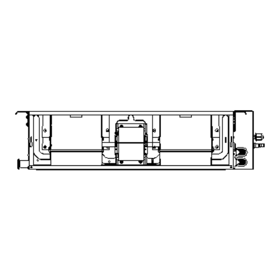
Ducted indoor units with adjustable ESP Installation Instructions Ⅲ 1 Outline Dimension Drawings of the Indoor Unit Note: the unit in the followings figures is mm, unless otherwise specified. Fig.1 is applicable to 09K、12K、18K、24K Fig.1 Table 1: Outline Dimensions: Unit: mm Item Model 09K、12K... -
Page 11: Dimension Requirements On The Installation Space Of The Indoor Unit
Ducted indoor units with adjustable ESP 2 Dimension Requirements on the Installation Space of the Indoor Unit Fig. 2 3 Installation of the Indoor Unit a. Requirements on the Installation Location 1) Ensure the hanger is strong enough to withstand the weight of the unit. 2) The drainage of the drain pipe is easy. - Page 12 Ducted indoor units with adjustable ESP between holes and see Fig.3 for the installation of the expansion bolt. Fig.3 Fig.4 Install the hanger on the indoor unit, as shown n Fig.4. Install the indoor unit on the ceiling, as shown in Fig.5. Fig.5 CAUTION!...
-
Page 13: Horizontality Check Of The Indoor Unit
Ducted indoor units with adjustable ESP prevent it vibrating. Consult the user and builder for more details. ③.If the strength of the ceiling is not strong enough, a beam made of angle iron can be used and then fix the unit on it. ④.If the indoor unit is not installed in the air conditioning area, please use sponge around the unit to prevent condensing. - Page 14 Ducted indoor units with adjustable ESP Fig.8 Name Name Hanger Transition Duct Return Air Duct Air Supply Duct Canvas Duct Diffuser Return Air Louver Diffuser Joint Air Supply Outlet Table 3 c.Installation Steps of the Round Air Supply Duct 1) Preinstall the outlet of the round duct on the transition duct and then fix it by the self-tapping screw.
-
Page 15: Drawings Of The Air Supply Outlet And Return Air Inlet
Ducted indoor units with adjustable ESP 6 Drawings of the Air Supply Outlet and Return Air Inlet capacity:2.5~6.0kW Fig.9 Air Supply Outlet Fig.10 Return Air Inlet Table 4 Dimensions of the Air Supply Outlet and Return Air Inlet (unit: mm) Dimension of air return Dimension of air outlet flange Item... -
Page 16: Installation Of The Condensate Pipe
Ducted indoor units with adjustable ESP and the other to the return air louver. For the sake of the convenience to freely adjust the height, a cutting of canvas duct will be helpful, which can be reinforce and folded by 8#iron wire. -
Page 17: Design Of The Drain Pipe
Ducted indoor units with adjustable ESP b. There is a condensate outlet on both left and right sides of the unit. Once one is confirmed to be used, the other should be clogged by a rubber plug, bundled by the binding wire and insulated by the insulation material to avoid water leakage. -
Page 18: Precautions For The Lift Pipe
Ducted indoor units with adjustable ESP (Right) with a min. degree of slope 1/100 (Wrong) Fig.14 e. Insert the drain hose into the drain hole and tighten it with clamps. f. Wrap the clamps with large amount of sponge for thermal insulation. g. -
Page 19: Test For The Drainage System
Ducted indoor units with adjustable ESP Fig.16 Notes: ①.The inclination height of the drain hose should be within 75mm so that the outlet of the drain hose does not suffer the external force. ②.If multiple drain pipes converge, please follow the installation steps below. Fig.17 12 Test for the Drainage System a. -
Page 20: Piping
Ducted indoor units with adjustable ESP 13 Piping a. Let the flare end of the copper pipe point at the screw and then tighten the screw by hand. b. After that, tighten the screw by the torque wrench unit it clatters (as shown in Fig.18). -
Page 21: Insulation For The Refrigerant Pipe
Ducted indoor units with adjustable ESP 14 Insulation for the refrigerant pipe a. The refrigerant pipe should be insulated by the insulating material and plastic tape in order to prevent condensing and leaking. b. The joints of the indoor unit should be wrapped with the insulating material and no gas is allowed on the joint of the indoor unit, as shown in Fig.19. - Page 22 Ducted indoor units with adjustable ESP 1) Strip the insulating layer at the end of the wire about 25mm off with a wire striper. 2) Loosen the screw off on the wiring board of the air conditioning unit. 3) Shape with the pliers the end of the wire to a circle matching with the size of the screw.
-
Page 23: Wiring Of The Power Cord (Single-Phase)
Ducted indoor units with adjustable ESP ⑤.During the wiring, the wiring terminal or the single-core wire must be used; the direct wiring between the multi-core wire and wiring board would cause fire. ⑥ .All wiring should be done strictly in accordance with the wiring diagram; otherwise the improper wiring would cause the air conditioning unit running abnormally or damaged. -
Page 24: Setting Of External Static Pressure
Ducted indoor units with adjustable ESP 17 Setting of External Static Pressure Press " Function " and " Timer " buttons continuously for 5s under off status to adjust the debugging menu. Press " Mode " button to adjust the set item and use " ▲ " or "... -
Page 25: Ⅳ Rated Working Conditions
Ducted indoor units with adjustable ESP Ⅳ Rated Working Conditions Table 9 Working Temperature Range Indoor side state Outdoor side stae Dry bulb temp. Wet bulb temp. Dry bulb temp. Wet bulb temp. ℃ ℃ ℃ ℃ Rated Cooling Max.Cooling Rated Heating Max.Heating —... - Page 26 Ducted indoor units with adjustable ESP Table of Error Codes for Indoor Unit Number Error code Error Compressor high pressure protection Indoor anti-freeze protection Compressor low pressure protection, refrigerant lack protection and refrigerant colleting mode Compressor high discharge temperature protection AC over-current protection Communication error Mode conflict...
-
Page 27: Ⅵ Maintenance
Ducted indoor units with adjustable ESP Ⅵ Maintenance CAUTION! Take notice of the following items before clean your air conditioning unit. ①. Cut off the main power supply before contact any wiring device. ②. Only when the unit is turn off and the main power supply is cut off, can the unit be cleaned;... - Page 28 Ducted indoor units with adjustable ESP Ⅵ Safety operation of flammable refrigerant Ⅰ Qualification requirement for installation and maintenance man All the work men who are engaging in the refrigeration system should bear the valid certification awarded by the authoritative organization and the qualification for dealing with the refrigeration system recognized by this industry.
- Page 29 Ducted indoor units with adjustable ESP a. Shut down the unit and cut power supply b. Eliminate the refrigerant c. Vacuuming d. Clean it with N e. Cutting or welding f. Carry back to the service spot for welding The refrigerant should be recycled into the specialized storage tank. Make sure that there isn’t any naked flame near the outlet of the vacuum pump and it’s well-ventilated.
- Page 30 Ducted indoor units with adjustable ESP www.argoclima.com...
- Page 31 WIRED CONTROLLER standard for DUCTED (MULTI ARGO) optional for CASSETTE (MULTI ARGO) Installation Manual MODELS matchings: standard for X3I ECO SD27-35-50-70HL optional for X3I ECO AS27-35-50-70HL Thank you for choosing an Argoclima commercial air conditioner. Please read this manual carefully before using the unit and retain it for future reference.
- Page 32 User Notice Never install the wired controller in the moist circumstance or expose it directly under the ◆ sunlight. ◆ Never beat, throw, and frequently disassemble the wired controller and the wireless remote controller. ◆ Never operate the wired controller and the wireless remote controller with wet hands. Do not remove or install the wired controller by yourself.
- Page 33 Contents Wired Controller ....................1 1 Symbols on LCD ................... 1 1.1 Outside View of the Wired Controller ..............1 1.2 LCD of the Wired Controller ................. 1 2 Buttons ......................2 2.1 Buttons on the Wired Controller ................2 2.2 Function of the Buttons ..................3 3 Operation Instructions ...................
-
Page 34: Symbols On Lcd
Wired Controller Wired Controller 1 Symbols on LCD 1.1 Outside View of the Wired Controller Fig.1 Outside View of the Wired Controller 1.2 LCD of the Wired Controller Fig.2 LCD of the Wired Controller... -
Page 35: Buttons
Wired Controller Table 1 Display Instruction of Display Automatic mode (under auto mode, the indoor unit will select its Auto operating mode according to the variation of room temperature) Cool Cooling mode Dry mode Fan mode Heat Heating mode Sleep Display when sleep function is set Fresh air Display when fresh air function is set... -
Page 36: Function Of The Buttons
Wired Controller 2.2 Function of the Buttons Table 2 Name Function Function selection and cancellation. ① SWING/ENTER Setting of the up and down swing function. ② ▲ Running temperature setting of the indoor unit, range:16~30°C(61~86°F). ① Timer setting, range:0.5-24 hr. ②... -
Page 37: Operation Instructions
Wired Controller 3 Operation Instructions 3.1 ON/OFF Press ON/OFF to turn on the unit and turn it off by another press. Note: The state shown in Fig.4 indicates the “OFF” state of the unit after power on. The state shown in Fig.5 indicates the “ON” state of the unit after power on. Fig. -
Page 38: Fan Setting
Wired Controller Fig.6 3.4 Fan Setting Under the “ON” State of the unit, press Fan and then fan speed of the indoor unit will change circularly as shown in Fig.7. Auto (Low) (Medium low) (Medium) (Medium high) (High) Fig.7 3.5 Timer Setting Under the “ON”/”OFF”... -
Page 39: Up & Down Swing Setting
Wired Controller Press “TIMER” button to set Press ▲ or ▼ button to adjust time Press “TIMER” button to cancel Press “SWING/ENTER” to finish timer setting timer setting Fig. 8 Timer off Setting under the “ON” State of the Unit Timer range: 0.5-24hr. -
Page 40: Left & Right Swing Setting
Wired Controller 3.7 Left & Right Swing Setting Swing On: Press FUNCTION under on state of the unit to activate the swing function. In this case, will blink. After that, press SWING/ENTER to make a confirmation. Swing Off: When the Swing function is on, press FUNCTION to enter the Swing setting interface, with blinking. -
Page 41: Fresh Air Function Setting
Wired Controller 3.8 Fresh Air Function Setting Valve Turn on fresh air valve function: Under unit on status, press FUNCTION button on the panel to select “Fresh air valve” function option. When icon flashes, it enters fresh air valve setting mode. Previous temperature display position will display the level of fresh air valve. -
Page 42: Sleep Setting
Wired Controller 3.9 Sleep Setting Sleep on: Press FUNCTION under on state of the unit till the unit enters the Sleep setting interface. Press SWING/ENTER to confirm the setting. Sleep off: When the Sleep function is activated, press FUNCTION to enter the Sleep setting interface. -
Page 43: Turbo Setting
Wired Controller 3.10 Turbo Setting Turbo function: The unit at the high fan speed can realize quick cooling or heating so that the room temperature can quickly approach the setting value. In the Cooling or Heating mode, press FUNCTION till the unit enters the Turbo setting interface SWING/ENTER When the Turbo function is activated, press FUNCTION to enter the Turbo setting interface and then press SWING/ENTER to cancel this function. -
Page 44: Energy Saving Function Setting
Wired Controller 3.11 Energy Saving Function Setting Turn on energy saving function: 1)Energy Saving Setting for Cooling When the unit runs under the COOL or DRY mode, press FUNCTION button to select "SAVE" function option, with "SAVE" flashing, and then press ▲ or ▼ to adjust the lower limit, after that, press the SWING/ENTER button to activate this function. -
Page 45: E-Heater Setting
Wired Controller 3.12 E-heater Setting E-heater (auxiliary electric heating function): In the Heating mode, E-heater is allowed to be Once the wired controller or the remote controller enters the Heating mode, this function will be turned on automatically. Press FUNCTION in the Heating mode to enter the E-heater setting interface and then press SWING/ENTER to cancel this function. -
Page 46: X-Fan Setting
Wired Controller 3.13 X-fan Setting X-fan function: After the unit is turned off, the water in evaporator of indoor unit will be automatically evaporated to avoid mildew. In the Cooling or Dry mode, press FUNCTION till the unit enters the X-fan setting interface and then press SWING/ENTER to active this function. -
Page 47: Quiet Function Setting
Wired Controller 3.14 Quiet Function Setting Turn on quiet function: Under unit on status, press FUNCTION button on the panel to select “Quiet” function option. When “Quiet” or “Auto quiet” flashes, it enters quiet function setting mode. Press ▲ or ▼ button to switch between “Quiet”... -
Page 48: Health Setting
Wired Controller 3.15 Health Setting Health on: Press FUNCTION under on state of the unit till the unit enters the Health setting interface. Press SWING/ENTER to confirm the setting. Health off: When the Health function is activated, press FUNCTION to enter the Health setting interface. -
Page 49: Absent Setting
Wired Controller 3.16 Absent Setting Absent on: Press FUNCTION under on state of the unit till the unit enters the Absent setting interface. Press SWING/ENTER to confirm the setting. Absent off: When the Absent function is activated, press FUNCTION to enter the Absent setting interface. -
Page 50: I-Demand Setting
Wired Controller 3.17 I-Demand Setting I-Demand on: Press FUNCTION under on state of the unit till the unit enters the I-Demand setting interface. Press SWING/ENTER to confirm the setting. I-Demand off: When the I-Demand function is activated, press FUNCTION to enter the I-Demand setting interface. -
Page 51: Wifi Function Setting
Wired Controller 3.18 WiFi Function Setting "Gree+" APP can be used to control it. Please scan the QR code to download it. APP can only set some common functions of WiFi wired controller: ON/OFF, mode, set temperature, FAN speed, etc. controller (reset WiFi to ex- When using the APP for the first time, please reset the WiFi function of wired... -
Page 52: Installation And Dismantlement
Wired Controller Select the temperature sensor at the wired controller under the cooling, dry and fan modes, ④ and select the temperature sensor at the return air inlet under the heating mode and auto modes (04 displayed in the timer display area). SWING/ENTER Pressing the button “ON/OFF”... - Page 53 Wired Controller Wired Controller Table 3 Front Panel Socket box Soleplate of the Name of the Wired Screw M4X25 embedded in the Wired Controller wall Controller Fig. 21 Note: CN1 is 485 communication interface and it used Wired Controller XE73-44/E for connecting the 4-core communication wire.
- Page 54 Wired Controller For matching with different models, the patch cord and the connection wire are provided in the packaging box of wired controller. As shown in fig. 22. Fig. 22: Schematic diagram of patch cord and connection wire ● If the air conditioner has been installed with the patch cord (fig. 24) used for connecting the wired controller.
- Page 55 Wired Controller Smart zone controller Fig. 26 Fig. 26 shows the schematic diagram of control system connection. Wired controller can connect the smart zone controller (integrated control system). “n” indicates the number of communication node address (programmable wired controller). The complete system is composed of the smart zone controller, wired controller and communication cable.
-
Page 56: Dismantlement Of The Wired Controller
Wired Controller cord and connection lines between the indoor and outdoor unit, with a minimum interval of 20cm, otherwise the communication of the unit will probably work abnormally. If the air conditioning unit is installed where is vulnerable to electromagnetic interference, ②... - Page 57 Table 4 Meaning of Each Error Error Error Error Error Code Code Return air temperature sensor open/short Drive board communication error circuited evaporator temperature sensor open/short Compressor overheating protection circuited Indoor unit liquid valve temperature sensor Indoor and outdoor units unmatched open/short circuited Indoor gas valve temperature sensor open/ Communication line misconnected or...
- Page 58 Wired Controller Table 4 Meaning of Each Error Error Error Error Error Code Code Communication error between IDU and IDU network address error grid connection Communication error between ODU and Ip address allocation overflow grid connection Main error at grid connection side...
- Page 59 www.argoclima.com...
Need help?
Do you have a question about the X3I ECO SD27HL and is the answer not in the manual?
Questions and answers