Table of Contents
Advertisement
Quick Links
Instruction Manual
D200163X012
Fisherr 4660 High-Low Pressure Pilot
Contents
. . . . . . . . . . . . . . . . . . . . . . . . . . . . . . . . .
. . . . . . . . . . . . . . . . . . . . . . . . . . . . .
. . . . . . . . . . . . . . . . . . . . . . . . . . . . . . . . .
. . . . . . . . . . . . . . . . . . . . . . . . .
. . . . . . . . . . . . . . . . . . . . . . . . . . . . . . .
. . . . . . . . . . . . . . . . . . . . . . . . . . . . . . . . . .
. . . . . . . . . . . . . . . . . . . . . . . . . . . . . . . . . .
. . . . . . . . . . . . . . . . . . . . . . . . . .
. . . . . . . . . . . . . . . . . . . . . . . . . .
. . . . . . . . . . . . . . . . . . . . . . . . .
. . . . . . . . . . . . . . . . . . . . . . . . .
. . . . . . . . . . . . . . . . . . . . . . . . . . . . . . . . . . . . . . .
. . . . . . . . . . . . . . . . . . . . . . . . .
. . . . . . . . . . . . . . . . . . . . . . . . . .
. . . . . . . . . . . . . . . . . . . . . . . . . . . . . . . . . . .
. . . . . . . . . . . . . . . . . . . . . . . . . . . . . . . .
. . . . . . . . . . . . . . . . . . . . . . . .
. . . . . . . . . . . . . . . . . . . . . . . . . . . . . . . .
. . . . . . . . . . . . . . . . . . . . . . . . . . . .
. . . . . . . . . . . . . . . . . . . . . . . . . . . .
. . . . . . . . . . . . . . . . . . . . . . . . . . . .
. . . . . . . . . . . . . . . . . . . . . . . . . . . . . . .
. . . . . . . . . . . . . . . . . . . . . . . . . . . . . . . . . . .
. . . . . . . . . . . . . . . . . . . . . . . . . . . . . . . . . . .
www.Fisher.com
. . . . . . . . . . . . . . . . . . . . . . .
. . . . . . . . . . . . . . . . . . . . . .
. . . . . . . . . . . . . . . . . . . . . . . .
. . . . .
. . . . . . . . . . . . . . . . .
. . . . . . . . . . . . . . . .
. . . . . . . . . . . . . . . . .
. . . . . . . .
. . . .
. . . . . . . . . . . . . . . .
. . . . . . . . .
. . . . . . . . . . . .
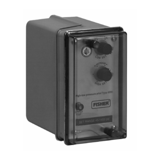
Figure 1. Fisher 4660 High-Low Pressure Pilot with
Relay
2
2
2
2
2
5
7
7
7
7
8
8
9
9
9
X0231
9
10
10
11
11
. .
12
14
15
15
15
16
16
17
17
18
18
19
19
19
20
20
X0232
22
4660 Pressure Pilot
FRONT VIEW
LEFT SIDE WITH CASE COVER OFF
May 2014
Advertisement
Table of Contents

Subscribe to Our Youtube Channel
Related Manuals for Emerson Fisherr 4660


Summary of Contents for Emerson Fisherr 4660
-
Page 1: Table Of Contents
Instruction Manual 4660 Pressure Pilot D200163X012 May 2014 Fisherr 4660 High‐Low Pressure Pilot Contents Figure 1. Fisher 4660 High‐Low Pressure Pilot with Relay Introduction ....... . . -
Page 2: Introduction
To avoid personal injury or property damage it is important to carefully read, understand, and follow all of the contents of this manual, including all safety cautions and warnings. If you have any questions about these instructions, contact your Emerson Process Management sales office. Description The 4660 high‐low pressure pilot (figure 1) activates emergency shutdown systems for flowlines, production vessels,... - Page 3 Instruction Manual 4660 Pressure Pilot D200163X012 May 2014 Table 1. Specifications Set Point DP Available Configurations (see table 2 or 3) Single High‐Low Unit: 10% for up to 172.4 bar (2500 High‐low, low‐only, or high‐only set point capability psig) Bourdon tubes; 15% for 344.8 and 517.1 bar (5000 and 7500 psig) Bourdon tubes Input Signal Low‐Only and High‐Only Pair: 3%...
- Page 4 Instruction Manual 4660 Pressure Pilot May 2014 D200163X012 Table 1. Specifications (continued) Safety Instrumented System Classification Declaration of SEP SIL3 capable certified by exida Consulting LLC Fisher Controls International LLC declares this product to be in compliance with Article 3 paragraph Approximate Weight 3 of the Pressure Equipment Directive (PED) 97 / 23 / EC.
-
Page 5: Installation
Instruction Manual 4660 Pressure Pilot D200163X012 May 2014 Table 4. Maximum Allowable Process Pressure MAXIMUM ALLOWABLE EMERGENCY PROCESS PRESSURE BOURDON TUBE RATING Stainless Steel Bourdon Tubes NACE Compliant Bourdon Tubes Psig Psig Psig 13.8 13.8 17.2 34.2 34.2 34.5 69.0 1000 69.0 1000... - Page 6 Instruction Manual 4660 Pressure Pilot May 2014 D200163X012 Figure 2. Typical Connection Schematics PROCESS NO. 2 SUPPLY SUPPLY PROCESS PROCESS NO. 1 OUTPUT OUTPUT OUTPUT B. LOW-ONLY AND HIGH/LOW PILOTS OUTPUT WITH DUAL OUTPUTS AND DIFFERENT PROCESS PRESSURES A. HIGH-ONLY AND LOW-ONLY PILOTS 38A6084-B SENSING A SINGLE PROCESS POINT AND HAVING A SINGLE OUTPUT...
-
Page 7: Mounting
Instruction Manual 4660 Pressure Pilot D200163X012 May 2014 Mounting Normal installation is with the pilot mounted vertically and with process, supply, and output connections facing downward as shown in figure 1. All key numbers are shown in figure 8 unless otherwise indicated. Actuator Mounting Pilots can be mounted on a control valve actuator as described below. -
Page 8: Pressure Connections
While use and regular maintenance of a filter that removes particles larger than 40 micrometers in diameter will suffice in most applications, check with an Emerson Process Management field office and industry instrument air quality standards for use with corrosive gas or if you are unsure about the proper amount or... -
Page 9: Process Pressure
Instruction Manual 4660 Pressure Pilot D200163X012 May 2014 Supply pressure must be clean, dry air or noncorrosive gas that meets the requirements of ISA Standard 7.0.01. A maximum 40 micrometer particle size in the air system is acceptable. Further filtration down to 5 micrometer particle size is recommended. -
Page 10: Pilots Without Optional Set Point Indication
Instruction Manual 4660 Pressure Pilot May 2014 D200163X012 point. For low‐only constructions, perform only those procedures that pertain to setting and checking the low set point. For high‐low constructions, perform procedures that pertain to both the high and low set points. WARNING Avoid personal injury or property damage from an uncontrolled process or sudden release of process pressure. -
Page 11: Setting The High Set Point
Instruction Manual 4660 Pressure Pilot D200163X012 May 2014 6. Connect an external pressure source to the process pressure connection. This external pressure source should be a regulated air or gas supply that is adjustable to zero. The external pressure source must be capable of supplying a process pressure that will be equal to or greater than the desired high set point pressure. -
Page 12: Alternate Set Point Adjustment Procedure
Instruction Manual 4660 Pressure Pilot May 2014 D200163X012 3. Slowly turn the low set point knob (key 67) clockwise until the low set point is obtained. The low set point is obtained when the output pressure of the pilot has changed from full output to zero. 4. - Page 13 Instruction Manual 4660 Pressure Pilot D200163X012 May 2014 4. Turn the HIGH SET knob counterclockwise until the high set point pivot just comes in contact with the flapper. The pilot should have full output pressure (green indication on the optional output indicator). 5.
-
Page 14: Pilots With Optional Set Point Indication
Instruction Manual 4660 Pressure Pilot May 2014 D200163X012 Low‐Only Construction 1. Refer to the WARNING at the beginning of the Operating Information section. Make sure the Bourdon tube contains no pressure. 2. Connect supply pressure to the pilot. WARNING Before continuing on with step 3, read this Warning: Natural gas, if used as the supply medium, will seep from the unit into the surrounding atmosphere when the SUPPLY TEST button is pushed. -
Page 15: Setting The High And/Or Low Set Point(S)
Instruction Manual 4660 Pressure Pilot D200163X012 May 2014 5. Connect an external pressure source to the process pressure connection. This external pressure source should be a regulated air or gas supply that is adjustable to zero. The external pressure source must be capable of supplying a process pressure that will be equal to or greater than the desired high set point pressure. -
Page 16: Startup
Instruction Manual 4660 Pressure Pilot May 2014 D200163X012 1. Remove the case cover screw (key 5) and the case cover (key 3). 2. Lift the end of the flapper off the nozzle beam approximately 19 mm (0.75 inch) by moving the opposite end of the flapper clockwise for a slight rotation. -
Page 17: Principle Of Operation
Instruction Manual 4660 Pressure Pilot D200163X012 May 2014 Principle of Operation Refer to the schematic in figure 7. The following explanation describes the principle of operation for a high‐low pilot. Figure 7. Principle of Operation Schematic LOW SETPOINT PIVOT PROCESS PRESSURE HIGH SET POINT PIVOT LOW SETPOINT ADJUSTMENT HIGH SETPOINT ADJUSTMENT... -
Page 18: Bourdon Tube/Flapper Assembly Replacement
Instruction Manual 4660 Pressure Pilot May 2014 D200163X012 WARNING Avoid personal injury or property damage from an uncontrolled process or sudden release of process pressure. Before starting disassembly: D Always wear protective clothing, gloves, and eyewear when performing any maintenance operations. D Do not remove the actuator from the valve while the valve is still pressurized. -
Page 19: Low Or High Set Point Assembly Replacement
Instruction Manual 4660 Pressure Pilot D200163X012 May 2014 7. Refer to the alignment of the nozzle beam procedure in the Operating Information section. 8. Replace the case cover, and attach it with the case cover screw. 9. Reset the high and/or low set points according to the procedures presented in the Operating Information section. Low or High Set Point Assembly Replacement Obtain the set point assembly listed in the parts kit section, then perform one or the other of the following procedures. -
Page 20: Parts Ordering
Use only genuine Fisher replacement parts. Components that are not supplied by Emerson Process Management should not, under any circumstances, be used in any Fisher instrument. Use of components not supplied by Emerson Process Management may void your warranty and hazardous area approval, might adversely affect the performance of the instrument, and could cause personal injury and property damage. - Page 21 Instruction Manual 4660 Pressure Pilot D200163X012 May 2014 Figure 8. 4660 Pilot Assembly SWITCH PT LOW ASSY SWITCH PT HIGH ASSY SET POINT KNOB OR SET POINT INDICATION ASSY RELAY ASSY BOURDON TUBE/ FLAPPER ASSY APPLY SEALANT 48A3536‐H Description Part Number Description Part Number Set Point Indicator...
-
Page 22: Parts List
(w/o set point indication) Locking Nut, aluminum/PTFE anodized Note (w/o set point indication) Part numbers are shown for recommended spares only. For part numbers not shown, contact your Emerson Process Management sales Locking Wedge, PPO office. (w/o set point indication) Range Label... - Page 23 Instruction Manual 4660 Pressure Pilot D200163X012 May 2014 Description Description Part Number Output Indicator Lock Washer, pl steel (not shown) Elbow Fitting, stainless steel Actuator Yoke Mounting (5 req'd) (output indicator) (2 req'd) Actuator Casing & Pipestand Tubing, Nylon (output indicator) Mounting (3 req'd) Tubing, polyethylene (output indicator (2 req'd) Pipe Clamp, pl steel (not shown)
- Page 24 Responsibility for proper selection, use, and maintenance of any product remains solely with the purchaser and end user. Fisher is a mark owned by one of the companies in the Emerson Process Management business unit of Emerson Electric Co. Emerson Process Management, Emerson, and the Emerson logo are trademarks and service marks of Emerson Electric Co.
Need help?
Do you have a question about the Fisherr 4660 and is the answer not in the manual?
Questions and answers