Table of Contents
Advertisement
Quick Links
Advertisement
Table of Contents

Related Manuals for Victron energy Digital Multi Control 200/200A


Summary of Contents for Victron energy Digital Multi Control 200/200A
- Page 1 ENGLISH Digital Multi Control Digital Multi Control 200/200A rev 00 - 10/2023...
-
Page 2: Table Of Contents
Digital Multi Control Table of Contents 1. Safety instructions ........................1 2. Introduction ........................... 2 2.1. Compatibility ......................... 2 2.2. Quick start guide ......................2 2.3. What's in the box ......................2 3. Features ..........................3 3.1. System connectivity ......................3 3.2. -
Page 3: Safety Instructions
Digital Multi Control 1. Safety instructions General • Review the included documentation for instructions before using this product. • This product has been tested in accordance with international standards. Only use this product for the intended purpose or application. • Never use the product in locations with a gas or dust explosion danger. Installation •... -
Page 4: Introduction
Digital Multi Control 2. Introduction The Digital Multi Control 200/200A enables remote monitoring and control of inverter/charger systems in stand-alone, parallel, and 2- or 3-phase configurations. It seamlessly integrates with the helm, dashboard or control panel of your vessel, vehicle, or home system. -
Page 5: Features
Digital Multi Control 3. Features 3.1. System connectivity The control panel integrates with the inverter/charger system, consisting of a single or multiple Inverter/chargers configured as a in stand-alone, parallel, and 2- or 3-phase system. 3.2. Power mode switch The switch can be used to turn the inverter/charger system on, off or to charger-only mode. 3.3. -
Page 6: System Types
Digital Multi Control 4. System types This chapter describes the different inverter/charger system types that the control panel can connect to. 4.1. MultiPlus system with 1 AC source Setup is easy, simply connect the control panel to the VE.Bus system (refer to the Inverter/charger connection [5] chapter), and it will automatically adapt to the system. -
Page 7: Installation
Digital Multi Control 5. Installation To install the control panel, you will need the following: • Use an RJ45 UTP cable to connect the control panel to the inverter/charger. The cable is available in a variety of lengths (30cm to 30m) and is not included with the control panel. •... -
Page 8: Configuration
Digital Multi Control 6. Configuration 6.1. Setup menu Configuration procedure: • To enter the configuration mode, press the button on the back of the control panel for about 4 seconds until the bottom LED in the right column starts blinking, indicating that the first parameter can be changed. •... -
Page 9: Scaling Factor
Digital Multi Control 6.2. Scaling factor This parameter only applies to pre-VE.Bus systems. Leave it at its default value of 1 for VE.Bus systems. For legacy pre-VE.Bus systems, refer to the Pre-VE.Bus scaling factor [11] chapter. 6.3. Generator current limit This parameter only applies when an external transfer switch is used and has no impact otherwise. - Page 10 Digital Multi Control 1. Press and hold the configuration button until the bottom LED in the left column starts flashing. This means you entered the configuration mode, and you can change the scaling factor. As said, this parameter can be ignored in the case of VE.Bus Multis.
-
Page 11: Operation
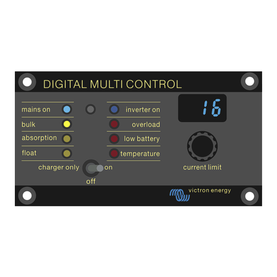
Digital Multi Control 7. Operation The control panel controls and monitors the inverter/charger system. The control panel is active as soon as the inverter/charger system is switched on. Description Charger LEDs: mains on, bulk, absorption and float. Light sensor, used to automatically dim the LED brightness. Inverter LEDs: inverter on, overload, low battery and temperature. -
Page 12: Led Brightness
Digital Multi Control AC voltage (V) rating Power (VA) rating Minimum configurable AC current limit (A) 1600 2.4 - 2.8 * 2000 2.4 - 4.5 * 3000 3.0 - 4.5 * 5000 3.9 - 6.4 * 8000 7.6 - 10.5 * 10000 8.6 - 10.5 * 15000... -
Page 13: Backward Compatibility With Legacy Pre-Ve.bus Units
Digital Multi Control 8. Backward compatibility with legacy pre-VE.Bus units The control panel is backwards compatible with legacy (pre-VE.Bus) inverter/chargers running firmware versions 15xxyyy, 17xxyyy, and 18xxyyy. The transition from pre-VE.Bus to VE.Bus occurred from late 2007 to mid-2008. For pre-VE.Bus systems, the control panel operation and setup align with the manual, except that the control panel does not automatically adapt to the system. -
Page 14: Configuration Example Pre-Ve.bus
Digital Multi Control 8.2.2. Configuration example pre-VE.Bus Four pre-VE.Bus Multis 30A/120V + 13kVA gen. (1500 rpm) + external transfer switch. For this configuration, the scaling factor must be calculated. The NrOfDevices is 4, the DeviceType is 2, so the scaling factor is (4 x 2) –... -
Page 15: Dimensions
Digital Multi Control 9. Dimensions Dimensions in mm ø 7.00mm b. ø 6.50mm ø 3.90mm d. ø 4.20mm Dimensions of metal panel REC020005000 Digital Multi Control 200/200A Revision : v1.0 Date : 01-09-2015 Page 1 of 1 Page 13 Dimensions... - Page 16 !! No rights can be derived from this drawing. doc: PN001501 Dimension diagram Victron Energy remote panels © victron energy b.v. article: metal panel date: 30-06-2015 rev: 02 Page 14...
Need help?
Do you have a question about the Digital Multi Control 200/200A and is the answer not in the manual?
Questions and answers