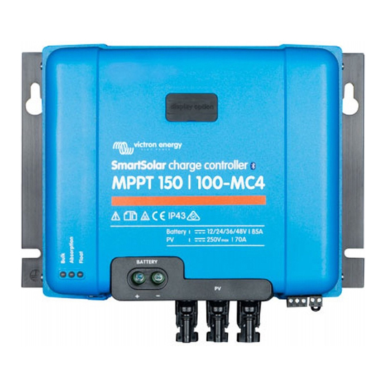
Victron energy SmartSolar MPPT 150/85 Series Manual
Charge controllers
Hide thumbs
Also See for SmartSolar MPPT 150/85 Series:
- Manual (70 pages) ,
- Manual (77 pages) ,
- Owner's manual (154 pages)
Subscribe to Our Youtube Channel
Summary of Contents for Victron energy SmartSolar MPPT 150/85 Series
- Page 1 Manual SmartSolar charge controllers MPPT 150/85-Tr MPPT 150/85-MC4 MPPT 150/100-Tr MPPT 150/100-MC4...
-
Page 2: General Description
1. General Description Bluetooth Smart built-in: dongle not needed The wireless solution to set-up, monitor and update the controller using Apple and Android smartphones, tablets or other devices. VE.Direct port For a wired data connection to a Color Control, PC or other devices. Remote on-off input On/off control by a VE.Bus BMS when charging Li-ion batteries. - Page 3 Automatic battery voltage recognition The controllers will automatically adjust to a 12V, 24V or a 48V system. A computer or a smartphone is required to set the controller to 36V. Adaptive three step charging The BlueSolar MPPT Charge Controller is configured for a three step charging process: Bulk –...
-
Page 4: Safety Instructions
2. Safety instructions Danger of explosion from sparking Danger of electric shock ● Please read this manual carefully before the product is installed and put into use. ● This product is designed and tested in accordance with international standards. The equipment should be used for the designated application only. -
Page 5: Installation
In case of thicker strands the contact area will be too small and the resulting high contact resistance will cause severe overheating, eventually resulting in fire. 3. Installation 3.1 General ● Mount vertically on a non-flammable surface, with the power terminals facing downwards. -
Page 6: Battery Charging Information
3.3 Cable connection sequence (see figure 1) First: connect the battery. Second: connect the solar array (when connected with reverse polarity, the controller will heat up but will not charge the battery). 3.4 More about automatic battery voltage recognition The system voltage is stored in non volatile memory. In case of a 24V or 48V battery, a reset (to 12V) occurs only when the output voltage decreases to less than 2V and the voltage on the PV input exceeds 7V. - Page 7 The absorption period also ends when the output current of the solar charger drops to less than 2Amps, not because of low solar array output but because the battery is fully charged (tail current cut off). This algorithm prevents over charge of the battery due to daily absorption charging when the system operates without load or with a small load.
-
Page 8: Automatic Equalization
A binary LED code helps determining the position of the rotary switch. After changing the position of the rotary switch, the LEDs will blink during 4 seconds as follows: Switch Blink position Float Bulk frequency Fast Slow Slow Slow Slow Slow Slow Slow... -
Page 9: Color Control
When automatic equalisation is not completely finished within one day, it will not resume the next day, the next equalisation session will take place as determined by the day interval. 3.9 LEDs LED indication: permanent on blinking Regular operation LEDs Bulk... - Page 10 3.11 Pluggable LCD display - Live data Remove the rubber seal that protects the plug on the front of the controller and plug-in the display module. The display is hot-swappable; this means that the charger may be operational while the display is plugged in. The following information will be displayed if the "-"...
- Page 11 Scrolling text Icons Segments Units Displayed info . Day V Daily battery voltage minimum Daily error 0 (most recent) Daily error 1 (shown when available) Daily error 2 (shown when available) ...
- Page 12 Scrolling text Segments Units Function or parameter Icons Relay minimum closed time - (minutes) .-.-.. °C mV Battery temperature compensation per cell (2) , h Bulk time protection ...
- Page 13 Day detection (panels irradiated) Load output 6) The parameter BMS present will be set to 'Y'es internally when a compatible BMS is detected, this setting can be used to revert the charger to normal operation (i.e. without BMS) by setting it manually to 'N'o. Do not set this parameter to 'Y'es when using a VE.Bus BMS connected to the remote on-off input.
-
Page 14: Troubleshooting
4. Troubleshooting Problem Possible cause Solution Reversed PV connection Connect PV correctly Charger does not function Reverse battery Non replacable fuse blown. connection Return to VE for repair Check battery A bad battery connection connection Cable losses too high Use cables with larger cross section Large ambient Make sure that... - Page 15 Using the pluggable LCD display or VictronConnect and the procedures below, most errors can be quickly identified. If an error cannot be resolved, please refer to your Victron Energy supplier. Error nr. Problem Cause / Solution n. a. The LCD does not light up...
- Page 16 Error nr. Problem Cause / Solution This error will not auto-reset. Err 26 Terminal overheated Power terminals overheated, check wiring and fasten bolts if possible. This error will auto-reset. Err 33 PV over-voltage This error will auto-reset after PV-voltage has dropped to safe limit.
-
Page 17: Specifications
5. Specifications SmartSolar charge controller MPPT 150/85 MPPT 150/100 Battery voltage 12/24/48V Auto Select (36V: manual) Maximum battery current 100A Maximum PV power, 12V 1a,b) 1200W 1450W Maximum PV power, 24V 1a,b) 2400W 2900W Maximum PV power, 36V 1a,b) 3600W 4350W Maximum PV power, 48V 1a,b) 4900W...


Need help?
Do you have a question about the SmartSolar MPPT 150/85 Series and is the answer not in the manual?
Questions and answers