
Related Manuals for Miller FieldPro Remote CE


Summary of Contents for Miller FieldPro Remote CE
- Page 1 OM-263 657C 2015−01 Processes Multiprocess Welding Description Arc Welding Power Source PipeWorx 350 FieldPro And FieldPro Remote File: Multiprocess Visit our website at www.MillerWelds.com...
- Page 2 We know you don’t have time to do it any other way. That’s why when Niels Miller first started building arc welders in 1929, he made sure his products offered long-lasting value and superior quality.
-
Page 3: Table Of Contents
TABLE OF CONTENTS SECTION 1 − SAFETY PRECAUTIONS - READ BEFORE USING ....... . . 1-1. - Page 4 TABLE OF CONTENTS SECTION 7 − MAINTENANCE & TROUBLESHOOTING ......... 7-1.
- Page 5 DECLARATION OF CONFORMITY for European Community (CE marked) products. MILLER Electric Mfg. Co., 1635 Spencer Street, Appleton, WI 54914, U.S.A. declares that the product(s) identified in this declaration conform to the essential requirements and provisions of the stated Council Directive(s) and Standard(s).
-
Page 7: Section 1 − Safety Precautions - Read Before Using
SECTION 1 − SAFETY PRECAUTIONS - READ BEFORE USING som 2013−09 Protect yourself and others from injury — read, follow, and save these important safety precautions and operating instructions. 1-1. Symbol Usage DANGER! − Indicates a hazardous situation which, if Indicates special instructions. - Page 8 D Remove stick electrode from holder or cut off welding wire at FUMES AND GASES can be hazardous. contact tip when not in use. D Wear body protection made from durable, flame−resistant material Welding produces fumes and gases. Breathing (leather, heavy cotton, wool). Body protection includes oil-free these fumes and gases can be hazardous to your clothing such as leather gloves, heavy shirt, cuffless trousers, high health.
-
Page 9: Additional Symbols For Installation, Operation, And Maintenance
1-3. Additional Symbols For Installation, Operation, And Maintenance FIRE OR EXPLOSION hazard. MOVING PARTS can injure. D Do not install or place unit on, over, or near D Keep away from moving parts such as fans. combustible surfaces. D Keep all doors, panels, covers, and guards D Do not install unit near flammables. -
Page 10: California Proposition 65 Warnings
1-4. California Proposition 65 Warnings Welding or cutting equipment produces fumes or gases This product contains chemicals, including lead, known to which contain chemicals known to the State of California to the state of California to cause cancer, birth defects, or other cause birth defects and, in some cases, cancer. -
Page 11: Section 2 − Consignes De Sécurité − Lire Avant Utilisation
SECTION 2 − CONSIGNES DE SÉCURITÉ − LIRE AVANT UTILISATION fre_som_2013−09 Pour écarter les risques de blessure pour vous−même et pour autrui — lire, appliquer et ranger en lieu sûr ces consignes relatives aux précautions de sécurité et au mode opératoire. 2-1. - Page 12 D Ne pas raccorder plus d’une électrode ou plus d’un câble de D Avoir recours à des écrans protecteurs ou à des rideaux pour masse à une même borne de sortie de soudage. Débrancher le protéger les autres contre les rayonnements les éblouissements câble pour le procédé...
-
Page 13: Dangers Supplémentaires En Relation Avec L'installation, Le Fonctionnement Et La Maintenance
LES BOUTEILLES peuvent exploser DES PIECES DE METAL ou DES si elles sont endommagées. SALETES peuvent provoquer des blessures dans les yeux. Les bouteilles de gaz comprimé contiennent du gaz sous haute pression. Si une bouteille est D Le soudage, l’écaillement, le passage de la endommagée, elle peut exploser. - Page 14 LES CHARGES ÉLECTROSTATI- RAYONNEMENT HAUTE QUES peuvent endommager les cir- FRÉQUENCE (H.F.) risque cuits imprimés. provoquer des interférences. D Établir la connexion avec la barrette de terre D Le rayonnement haute fréquence (H.F.) peut avant de manipuler des cartes ou des pièces. provoquer des interférences avec les équi- pements de radio−navigation et de com- D Utiliser des pochettes et des boîtes antista-...
-
Page 15: Proposition Californienne 65 Avertissements
2-4. Proposition californienne 65 Avertissements Les équipements de soudage et de coupage produisent des Ce produit contient des produits chimiques, notamment du fumées et des gaz qui contiennent des produits chimiques plomb, dont l’État de Californie reconnaît qu’ils provoquent dont l’État de Californie reconnaît qu’ils provoquent des mal- des cancers, des malformations congénitales ou d’autres formations congénitales et, dans certains cas, des cancers. -
Page 16: Section 3 − Definitions
SECTION 3 − DEFINITIONS 3-1. Additional Safety Symbols And Definitions Some symbols are found only on CE products. Warning! Watch Out! There are possible hazards as shown by the symbols. Safe1 2012−05 When power is applied failed parts can explode or cause other parts to explode. Safe26 2012−05 3-2. -
Page 17: Section 4 − Specifications
SECTION 4 − SPECIFICATIONS 4-1. Serial Number And Rating Label Location The serial number and rating information for this product is located on the rear. Use rating label to determine input power requirements and/or rated output. For future reference, write serial number in space provided on back cover of this manual. 4-2. -
Page 18: Dimensions And Weight
4-4. Dimensions And Weight Power Source 100 lb (45.4 kg) 22 in. (559 mm) 17 in. (432 mm) 12 in. (305 mm) Remote 9.08 lb (4.12 kg) 9.75 in. 11.6 in. (247.7 mm) (294.6 mm) 4.6 in. 116.8 mm) 18 in. (457.2 mm) 18 in. -
Page 19: Environmental Specifications
4-5. Environmental Specifications A. IP Rating IP Rating IP23 This equipment is designed for outdoor use. It may be stored, but is not intended to be used for welding outside during precipitation unless sheltered. IP23S 2014−06 B. Information On Electromagnetic Fields (EMF) This equipment shall not be used by the general public as the EMF limits for the general public might be exceeded during welding. -
Page 20: Section 5 − Installation
SECTION 5 − INSTALLATION 5-1. Selecting a Location Lifting Forks Use lifting forks or hand cart to move unit. If using lifting forks, extend forks Movement Do not move or operate unit beyond opposite side of unit. where it could tip. Lifting Handles Use handles to lift unit. -
Page 21: Proper Method To Carry Remote
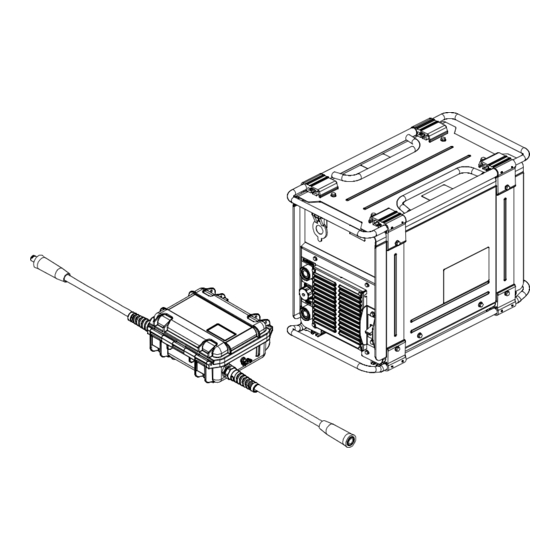
5-2. Proper Method To Carry Remote Handle Carry Remote only by using the handle. 255 409-B 5-3. Remote 14 Receptacle Information Socket* Socket Information C L N 14 volts DC. Circuit limited to 35 mA. 14 VOLTS DC Contact closure to A completes contactor control circuit. -
Page 22: Electrical Service Guide
5-4. Electrical Service Guide Elec Serv 2014−01 NOTICE − INCORRECT INPUT POWER can damage this welding power source. Phase to ground voltage shall not exceed +10% of rated input voltage. NOTICE − Actual input voltage should not be 10% less than minimum and/or 10% more than maximum input voltages listed in table. If actual input voltage is outside this range, output may not be be available. -
Page 23: Connecting 3-Phase Input Power
5-5. Connecting 3-Phase Input Power = GND/PE Earth Ground Tools Needed: input2 2012−05 − 803 766-C / Ref. 255 179-B OM-263 657 Page 17... - Page 24 5-5. Connecting 3-Phase Input Power (Continued) voltage available at site. This unit can be con- Input Conductors (L1, L2 And L3) Installation must meet all National and nected to any input power between 208 and Local Codes − have only qualified per- Disconnect Device Line Terminals 575 VAC without removing cover to relink the sons make this installation.
-
Page 25: Weld Output Receptacles And Selecting Cable Sizes
**Weld cable size (AWG) is based on either a 4 volts or less drop or a current density of at least 300 circular mils per ampere. ( ) = mm for metric use. ***For distances longer than those shown in this guide, call a factory applications rep. at 920-735-4505 (Miller) or 1-800-332-3281 (Hobart) Ref. S-0007-K 2013−10 OM-263 657 Page 19... -
Page 26: Stick Connections
5-7. Stick Connections Work Output Terminal Connect work lead to work output terminal. Electrode Output Terminal Connect electrode holder electrode output terminal. 255 358-B Notes OM-263 657 Page 20... -
Page 27: Tig Lift-Arct Connections
5-8. TIG Lift-Arct Connections Work Output Terminal Connect work lead to work output terminal. Electrode Output Terminal Connect TIG torch with gas valve to electrode output terminal. Gas Cylinder Cylinder Valve Open valve slightly so gas flow blows dirt from valve. Close valve. Regulator/Flowmeter Flow Adjust Typical flow rate is 15 cubic feet per... -
Page 28: Connecting Work Sense Lead To Remote
5-9. Connecting Work Sense Lead To Remote The work sense lead is re- quired for operation of the FieldPro Remote. Lead Ring Terminal 1/2 in. If using a ring terminal, slide terminal onto post on the remote. Wing Nut Once terminal or wire is on post, tighten wing nut. -
Page 29: Connecting Basic Feeder
5-11. Connecting Basic Feeder Turn Off wire feeder and welding power source. Stop engine on welding generator. Welding Power Source Gas Hose Weld Cable To Feeder Work Cable To Workpiece Weld cable and work cable connec- tions to power source (DCEN/ DCEP) are dependant on wire type. -
Page 30: Installing Welding Power Source Onto Rack
5-13. Installing Welding Power Source Onto Rack Rack − 195466 Universal Inverter Rack Mounting Kit − 301100 One Kit Per Machine (See OM-259 463 For rack setup and operation) Have only qualified persons make this installation. Turn welding power sources before inspecting or installing rack. -
Page 31: Connecting To Remote
5-14. Connecting To Remote This power source can be used with either FieldPro Remote, RHC−14 remote, wireless remote (see RHC−14 remote or wireless remote Owner’s Manual for operating instructions). Power Source TIG Torch (Shielding Gas Not Shown) Electrode Holder RHC-14 Or Wireless Remote Connection When using an RHC-14 or wireless remote, connect TIG torch or electrode holder directly to the... -
Page 32: Volt Sense Lead And Work Cable Connections For Multiple Welding Arcs
5-15. Volt Sense Lead And Work Cable Connections For Multiple Welding Arcs A. Ideal Setup 255 378-B Welding Power Source Work Sense Lead Remote Workpiece Weld Cable The work sense lead is required for This arrangement is an ideal setup for Work Cable operation of the FieldPro Remote. - Page 33 B. Bad Setup 255 379-B Welding Power Source Work Sense Lead This arrangement is a bad setup. Clamps for separate units should not be shared. Weld Cable Remote Weld cables should not be crossed. Work Cable Workpiece OM-263 657 Page 27...
-
Page 34: Section 6 − Operation
SECTION 6 − OPERATION 6-1. Welding Power Source And Remote Interface Controls 255 429-B / 264 180-B / Ref. 255 179-B / 253 664-A Power Switch Stick Electrode Type Select Button IN USE Button Amperage Adjustment Buttons AMPS Display 10 IN USE Indicator 14-Pin Remote Connected Indicator TIG Process Select Button 11 Check Polarity Indicator... -
Page 35: Welding Power Source And Remote Interface Operation Description
6-2. Welding Power Source And Remote Interface Operation Description Power Switch Use this switch to power up or power down the welding power source. The fan is thermostatically controlled and only runs when cooling is needed. AMPS Display This display illuminates and shows amperage for either TIG or stick welding process. Measured amperage just prior to the end of a welding operation will appear on the display for ten seconds after welding operation. -
Page 36: Lift-Arc Tig Procedure
6-3. Lift-Arc TIG Procedure With Process Switch in the TIG position, start an arc as follows: TIG Electrode Workpiece Touch tungsten electrode to work- piece at weld start point. Arc will not start while electrode is touching the workpiece. Slowly lift electrode to form an arc. -
Page 37: Carbon Arc Gouging
6-5. Carbon Arc Gouging Direction Of Travel 258 443-A Electrode Holder Keep the arc short. valve. Use proper arc and travel speed to create the desired shape and condition of Choose correct electrode holder for the Workpiece the gouge. process. Start air compressor and adjust regulator Air Stream Always cut away from the operator as... -
Page 38: Section 7 − Maintenance & Troubleshooting
SECTION 7 − MAINTENANCE & TROUBLESHOOTING 7-1. Routine Maintenance Disconnect power Maintain more often before maintaining. during severe conditions. 3 Months Repair Or Replace Replace Cracked Replace Damaged Or Torch Body Cracked Unreadable Cables Labels Repair Or Replace Cracked Cables And Cords Clean Tighten Weld... -
Page 39: Welding Power Source And Remote Diagnostics Help Codes
7-3. Welding Power Source And Remote Diagnostics Help Codes Display Example Display Code Fault Description Primary Transformer Over Current Indicates a malfunction in the primary power circuit. Secondary Thermistor Malfunction Indicates the left side thermal protection circuitry is malfunctioning. Secondary Circuit Over Temperature Indicates left side of unit has overheated. -
Page 40: Feeder Diagnostics Help Codes
7-4. Feeder Diagnostics Help Codes The FieldPro Feeder does not display the same help codes as the power source. Error conditions are indicated by a “HLP” message on the display, or by the blinking of the Red LED on motor board PC1. To view the Red LED, turn off the power source, remove the wrapper, and turn power source back on. -
Page 41: Troubleshooting Welding Power Source Issues
7-6. Troubleshooting Welding Power Source Issues If the welding power source is NOT responding after everything is connected, follow the items listed below before contacting the nearest factory-authorized service agent: Welding power source is plugged in and there is no power after turning on unit. If unit is directly connected to a line disconnect box or plugged into a receptacle from a line disconnect box, be sure that the line disconnect switch or main breaker is in the ON position. -
Page 42: Updating Software In Welding Power Source
19. Using the − and + buttons, adjust the display to match the measured value. 20. Wait a few seconds, then verify display and voltmeter reading are the same. 21. Press the TIG button to save the calibration setting. 22. Press ELECTRODE button to exit calibration mode or continue on to Amperage Calibration procedure. Amperage Calibration Procedure: 1. - Page 43 Notes OM-263 657 Page 37...
-
Page 44: Section 8 − Electrical Diagram
SECTION 8 − ELECTRICAL DIAGRAM Figure 8-1. Welding Power Source Circuit Diagram OM-263 657 Page 38... - Page 45 269 202-A OM-263 657 Page 39...
- Page 46 255 132-B Figure 8-2. Remote Circuit Diagram OM-263 657 Page 40...
- Page 47 Notes OM-263 657 Page 41...
-
Page 48: Section 9 − Parts List
SECTION 9 − PARTS LIST Hardware is common and not available unless listed. 255 178-E Figure 9-1. Welding Power Source Parts Assembly OM-263 657 Page 42... - Page 49 Quantity Model Item Dia. Part Mkgs. Description 907633 Figure 9-1. Welding Power Source Parts Assembly ....257114 Base ............
- Page 50 Quantity Model Item Dia. Part Mkgs. Description 907633 Figure 9-1. Welding Power Source Parts Assembly (Continued) ... . . 260280 Circuit Card Assy, Interconnect W/Label And Clips ....
- Page 51 ..... 121389 Label, Miller 12.437 x 5.250 Horizontal ......
- Page 52 Hardware is common and not available unless listed. 255 407-B Figure 9-2. Remote Parts Assembly OM-263 657 Page 46...
- Page 53 Quantity Model Item Dia. Part Mkgs. Description 301176 Figure 9-2. Remote Parts Assembly ....+253680 Case, Molded (Including) .........
- Page 54 Notes...
- Page 55 Effective January 1, 2015 (Equipment with a serial number preface of MF or newer) This limited warranty supersedes all previous Miller warranties and is exclusive with no other guarantees or warranties expressed or implied. Warranty Questions? LIMITED WARRANTY − Subject to the terms and conditions below, 6 Months —...
- Page 56 Contact the Delivering Carrier to: File a claim for loss or damage during shipment. For assistance in filing or settling claims, contact your distributor and/or equipment manufacturer’s Transportation Department. © ORIGINAL INSTRUCTIONS − PRINTED IN USA 2015 Miller Electric Mfg. Co. 2015−01...
Need help?
Do you have a question about the FieldPro Remote CE and is the answer not in the manual?
Questions and answers