Table of Contents
Troubleshooting

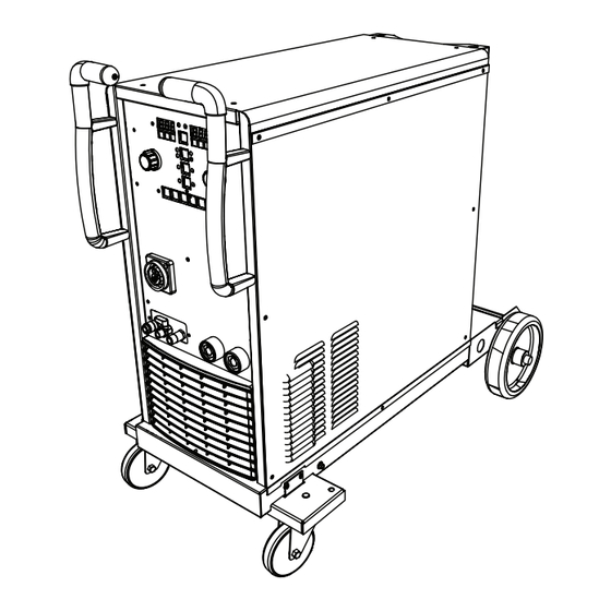
Related Manuals for Miller Blue Fab C350i


Summary of Contents for Miller Blue Fab C350i
- Page 1 OM-294252B 2023-11 Processes Multiprocess Welding Description Arc Welding Power Source with Wire Feeder Blue Fab C350i OWNER’S MANUAL For product information, Owner’s Manual translations, and more, visit www.MillerWelds.com...
- Page 2 We know you don’t have time to do it any other way. That’s why when Niels Miller first started building arc welders in 1929, he made sure his products offered long-lasting value and superior quality.
-
Page 3: Table Of Contents
TABLE OF CONTENTS SECTION 1 – SAFETY PRECAUTIONS – READ BEFORE USING..............1 Symbol Usage . - Page 4 DECLARATION OF CONFORMITY for European Community (CE marked) products. Orbitalum Tools, Business Unit Miller Europe, Josef Schüttlerstrasse 17, 78224, Singen Germany, declares that the product(s) identified in this declaration conform to the essential requirements and provisions of the stated Regulation(s) and Standard(s).
- Page 5 DECLARATION OF CONFORMITY for United Kingdom (UKCA marked) products. Orbitalum Tools, Business Unit Miller Europe, Josef Schüttlerstrasse 17, 78224, Singen Germany, declares that the product(s) identified in this declaration conform to the essential requirements and provisions of the stated Regulation(s) and Standard(s).
- Page 6 EMF DATA SHEET FOR ARC WELDING POWER SOURCE Product/Apparatus Identification Product Stock Number BlueFab C350i Air cooled 3300000001 BlueFab C350i Water cooled 3300000002 Compliance Information Summary Applicable regulation Directive 2014/35/EU Reference limits Directive 2013/35/EU, Recommendation 1999/519/EC Applicable standards IEC 62822-1:2016, IEC 62822-2:2016 Intended use ☒ for occupational use ☐...
-
Page 7: Section 1 - Safety Precautions - Read Before Using
SECTION 1 – SAFETY PRECAUTIONS – READ BEFORE USING Protect yourself and others from injury—read, follow, and save these important safety precautions and operating instructions. 1-1. Symbol Usage DANGER! – Indicates a hazardous situation which, if not avoided, will result in death or serious injury. The possible hazards are shown in the adjoining symbols or explained in the text. -
Page 8: Welding Can Cause Fire Or Explosion
HOT PARTS can burn. WELDING can cause fire or explosion. � Do not touch hot parts bare handed. � Allow cooling period before working on equipment. Welding on closed containers, such as tanks, drums, or pipes, can cause them to blow up. �... -
Page 9: Additional Hazards For Installation, Operation, And Maintenance
� Never weld on a pressurized cylinder—explosion will result. CYLINDERS can explode if � Use only correct compressed gas cylinders, regulators, hoses, damaged. and fittings designed for the specific application; maintain them Compressed gas cylinders contain gas under high and associated parts in good condition. pressure. -
Page 10: California Proposition 65 Warnings
� To reduce possible interference, keep weld cables as short as ARC WELDING can cause possible, close together, and down low, such as on the floor. interference. � Locate welding operation 100 meters from any sensitive electronic equipment. � Electromagnetic energy can interfere with sensitive electronic equipment such as microprocessors, �... -
Page 11: Section 2 - Definitions
Safe44 2012 Safe16 2017 Safe25 2012 1-1. Additional Safety Symbols And Definitions SECTION 2 – DEFINITIONS Engine fuel plus flames or sparks can cause fire. Do not cut on drums or any closed containers. When power is applied failed parts can explode or cause other parts to explode. Some symbols are found only on CE products. - Page 12 Gas Tungsten Arc Welding (GTAW) / Negative Wire Feed Tungsten Inert Gas (TIG) Welding Positive Material Thickness Inductance Two-Step Trigger Operation Input Voltage Arc Force (DIG) Four-Step Trigger Operation Suitable for Welding in an Environment Arc Length with Increased Risk of Electric Shock Rated No-Load Volt- MMA Welding...
-
Page 13: Section 3 - Specifications
Information About Default Weld Parameters And Settings NOTICE – Each welding application is unique. Although certain Miller Electric products are designed to determine and default to certain typical welding parameters and settings based upon specific and relatively limited application variables input by the end user, such default settings are for reference purposes only;... -
Page 14: Coolant Specifications
3-6. Coolant Specifications Do not use conductive coolant. Application Coolant GTAW Or Where High Frequency Current Is Used Low Conductivity Coolant 043810* Distilled Or Deionized Water Okay Above 32°F (0°C) GMAW Or Where High Frequency Current Is Not Used Low Conductivity Coolant 043810* Aluminum Protecting Coolant 043809* Distilled Or Deionized Water Okay Above 32°F (0°C) Where Coolant Contacts Aluminum Parts... -
Page 15: Duty Cycle And Overheating
3-8. Duty Cycle And Overheating Duty Cycle is percentage of 10 minutes that unit weld rated load without overheating. If unit overheats, thermostat(s) opens, output stops, and cooling fan runs. Wait fifteen mi- nutes for unit to cool. Reduce amperage or voltage, or duty cycle before welding. -
Page 16: Section 4 - Installation
A complete Parts List is available at www.MillerWelds.com Writers: Remember to move unit dimension and weight and rating la- SECTION 4 – INSTALLATION bel location information to the appropriate sections. 4-1. Selecting A Location 1-3. Selecting A Location nit dimension and weight and rating la- Do not move or operate unit where Movement it could tip. -
Page 17: Installing Running Gear
4-2. Installing Running Gear 1 Caster Wheels (2) 2 Plates (2) 3 M10 Nuts (2) 4 Wheel Bracket 5 12 x 24 Washers (2) 6 M12 Nuts (2) Assemble front caster wheels as shown. Use handles on front of power source to lift ma- chine onto casters. -
Page 18: Selecting Cable Sizes
4-3. Selecting Cable Sizes* NOTICE – The Total Cable Length in Weld Circuit (see table below) is the combined length of both weld cables. For example, if the power source is 30 m (100 ft) from the workpiece, the total cable length in the weld circuit is 60 m (2 cables x 30 m). Use the 60 m (200 ft) column to determine cable size. -
Page 19: Back Panel Connections
4-5. Back Panel Connections 1 Power Switch 2 Input Power Cord 3 Gas Fitting (5/8 UMF B) 4 Cooler Fill OM-294252 Page 13... -
Page 20: Installing Gas Supply
4-6. Installing Gas Supply Obtain gas cylinder and chain to running gear, wall, or other stationary support so cyl- inder cannot fall and break off valve. 1 Cap 2 Cylinder Valve Remove cap, stand to side of valve, and open valve slightly. Gas flow blows dust and dirt from valve. -
Page 21: Installing Wire Spool And Adjusting Hub Tension
Spacers Use only for 5 kg (11 lb) spool. 4-7. Installing Wire Spool And Adjusting Hub Tension 1 Spacers Hub Assembly Use only for 5 kg (11 lb) spool. tools/ 15 Kg (33 lb) 5 Kg (11 lb) Wire Spool Wire Spool Assembly Assembly... -
Page 22: Connecting 3-Phase Input Power
4-9. Connecting 3-Phase Input Power Installation must meet all National and Local Codes—have only quali- fied persons make this installation. Disconnect and lockout/tagout in- put power before connecting input conductors from unit. Follow es- tablished procedures regarding the installation and removal of lockout/tagout devices. -
Page 23: 4-10. Installing Welding Gun
4-10. Installing Welding Gun 1 Gun/Feeder Adapter 2 Gun Connector Insert gun connector into adapter. Tighten locking ring. 4-11. Installing Wire Guide And Drive Roll 1 Pressure Rolls 2 Feed Rolls 3 Drive Roll 4 Inlet Wire Guide Loosen screw. Slide tip of inlet wire guide as close to drive rolls as possible without touch- ing. -
Page 24: 4-12. Installing And Threading Welding Wire
4-12. Installing And Threading Welding Wire tools/ philips head wrench crescent wrench tools/ steelbrush nutdriver allen_wrench allen_set flathead philips head wrench crescent wrench chippinghammer 15/16 in. philips head wrench crescent wrench pliers needlenose knife steelbrush nutdriver light-duty workclamp wirecutter frontcutter Adjust tension nut so wire is taut when wire B. -
Page 25: Section 5 - Operation
SECTION 5 – OPERATION 5-1. Front Panel Controls Menu Memory Clear / Job 77650713 1 Left Display 5 Left Encoder Knob 9 Menu Button 2 Right Display 6 Right Encoder Knob 10 Memory Buttons 3 Input Power LED 7 Process Select Button 11 Clear/Job Button 4 Output On LED 8 Trigger Mode Select Button... -
Page 26: Initial Setup Menu
5-2. Initial Setup Menu 1 Left Display 2 Right Display 3 Left Encoder Knob 4 Right Encoder Knob 5 Menu Button 6 Process Button The initial setup menu allows the user to set various parameters for the welding power source. Menu To enter initial setup menu, first turn off the welder. -
Page 27: Section 6 - Mig Operation
SECTION 6 – MIG OPERATION 6-1. MIG Connections 1 Welding Power Source 2 Gas Cylinder 3 Gas Hose 4 Welding Gun Connect welding gun to welding torch con- nector on front o fpower sourcev. 5 Work Lead Connect work lead to negative weld output terminal. -
Page 28: Inductance
6-3. Inductance 1 Inductance LED 2 Menu Button 3 Right Encoder Knob 4 Left Display 5 Right Display When in the MIG process, press the Menu button to set inductance. The Inductance LED will blink. The left dis- play will read P50. The right display will show an inductance value between 0 and 50. -
Page 29: Synergic Mig Mode
Plus Mode Left Display Parameter Manual 2T Manual 4T Synergic 2T Synergic 4T Dynamic/Inductance 0 to 50 –20 to 20 Hot Start WFS m/min % (m/min) Hot Start Voltage/Arc 12.0 volts to Max voltage –9.9 to 9.9 volts Length Hot Start Time 0.0 to 10.0 seconds 0.0 to 10.0 seconds Hot Start Ramp Time... -
Page 30: Save And Recall (Mig Only)
6-7. Save And Recall (MIG Only) 1 Program Buttons 1–4 2 Left Display 3 Right Display Save To save weld settings, press and hold the de- sired Program button (1–4). The left display will show SAV. The right display will show the program number. -
Page 31: Section 7 - Mma (Stick) Operation
SECTION 7 – MMA (STICK) OPERATION 7-1. MMA (Stick) Connections 1 Negative Weld Output Terminal 2 Work Cable 3 Positive Weld Output Terminal 4 Electrode Holder Disconnect wire feeder from welding power source. Connect work cable to negative weld output terminal. -
Page 32: Mma (Stick) Welding
7-2. MMA (Stick) Welding 1 Process Button 2 MMA LED 3 Left Display 4 Right Display 5 Left Encoder Knob 6 Right Encoder Knob 7 Menu Button MMA Mode Press the Process button until the MMA LED illuminates to enable MMA mode. Menu Amperage will be shown on the left display. -
Page 33: Section 8 - Tig Operation
SECTION 8 – TIG OPERATION 8-1. TIG Connections 1 Positive Weld Output Terminal 2 Work Cable 3 Negative Weld Output Terminal 4 TIG Torch 5 Gas Hose Connect the work cable to the positive weld output terminal. Connect the work clamp to the workpiece. -
Page 34: Tig Welding
8-2. TIG Welding 1 Process Button 2 TIG LED 3 Left Display 4 Right Display 5 Left Encoder Knob TIG Mode Press the Process button until the TIG LED illuminates to enable TIG mode. Amperage will be shown on the left display. Menu Use the left encoder knob to adjust amperage. -
Page 35: Section 9 - Maintenance And Troubleshooting
SECTION 9 – MAINTENANCE AND TROUBLESHOOTING 9-1. Routine Maintenance Disconnect power before maintaining. � Service equipment more often if used in severe conditions. Every Every Every Reference Maintenance Schedule Section Months Months Months Coolant Filter Clean coolant filter. NOTICE – Severe conditions may require more fre- �... -
Page 36: Blowing Out Inside Of Unit
9-3. Blowing Out Inside Of Unit Do not remove case when blowing out inside of unit. To blow out unit, direct airflow through front and back louvers as shown. 9-4. Error Codes Code Description Remedy Current sensor error. Cycle power to the welding power source. If error persists, contact factory authorized service agent. -
Page 37: Troubleshooting
9-5. Troubleshooting Trouble Remedy No weld output; unit completely Place line disconnect switch in On position (see Section 4-9). inoperative. Check and replace line fuse(s), if necessary, or reset circuit breaker (see Section 4-9). Check for proper input power connections (see Section 4-9). No weld output. -
Page 38: Section 10 - Electrical Diagrams
SECTION 10 – ELECTRICAL DIAGRAMS Figure 10-1. Circuit Diagram For BlueFab C350i OM-294252 Page 32... - Page 39 S9850028 OM-294252 Page 33...
- Page 40 Figure 10-2. Circuit Diagram For Cooler OM-294252 Page 34...
- Page 41 Notes...
- Page 42 Notes...
- Page 43 Effective January 1, 2023 (Equipment with a serial number preface of ND or newer) This limited warranty supersedes all previous Miller warranties and is exclusive with no other guarantees or war- ranties expressed or implied. � Automatic Motion Devices LIMITED WARRANTY - Subject to the terms and 1.
-
Page 44: Owner's Record
Miller Europe / Orbitalum Tools shipment. GmbH For assistance in filing or settling claims, con- Singen, DE Phone: +49 7731 792400 tact your distributor and/or equipment manu- facturer’s Transportation Department. ORIGINAL INSTRUCTIONS – PRINTED IN USA © Miller Electric Mfg. LLC 2023-11...
Need help?
Do you have a question about the Blue Fab C350i and is the answer not in the manual?
Questions and answers