
Subscribe to Our Youtube Channel
Related Manuals for Pickering LXI 65-231-9 Series


Summary of Contents for Pickering LXI 65-231-9 Series
- Page 1 65-231-9xx User Manual LXI Modular High Voltage Multiplexer PRELIMINARY PRELIMINARY pickeringtest.com Issue D August 2023...
- Page 2 © COPYRIGHT (2023) PICKERING INTERFACES. ALL RIGHTS RESERVED. No part of this publication may be reproduced, transmitted, transcribed, translated or stored in any form, or by any means without the written permission of Pickering Interfaces. Technical details contained within this publication are subject to change without notice.
- Page 3 Pickering Interfaces strives to fulfil all relevant environmental laws and regulations and reduce wastes and releases to the environment. Pickering Interfaces aims to design and operate products in a way that protects the environment and the health and safety of its employees, customers and the public. Pickering Interfaces endeavours to develop and manufacture products that can be produced, distributed, used and recycled, or disposed of, in a safe and environmentally friendly manner.
- Page 4 PRODUCT SAFETY SAFETY SYMBOLS The following safety symbols may be used on the product and throughout the product documentation. MEANING / DESCRIPTION SYMBOL PROTECTIVE EARTH (GROUND) To identify any terminal which is intended for connection to an external conductor for protection against electric shock in case of a fault, or the terminal of a protective earth (ground) electrode.
-
Page 5: Table Of Contents
CONTENTS Copyright Statement .............ii Technical Support and Warranty .........iii Contents (this page) ..............v Warnings & Cautions ............vii Section 1 Technical Specification ............1.1 Section 2 Technical Desctiption ............2.1 Functional Description ..........2.1 Hardware Interlock ...........2.6 Section 3 Installation ................3.1 Installing the Unit .............3.1 Section 4 Programming Guide ............4.1... - Page 6 THIS PAGE INTENTIONALLY BLANK LXI Modular High Voltage Multiplexer 65-231-9xx Page vi...
-
Page 7: Warnings & Cautions
I/O signals that may be present. Blanking panels are available to order from Pickering. If the product is not used in this manner for example by using an extender card then additional care must be taken to avoid contact with exposed signals. - Page 8 • Appropriate manual handling procedures should be followed as dictated by the weight of the individual module or the combined weight of the modules & chassis. pickering pickering • Should a fault occur with the module or chassis, immediately isolate and disconnect the incoming power to the chassis and the user I/O signals.
-
Page 9: Technical Specification
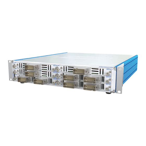
To aid with the user flexibility and ease of maintenance. experience the Pickering Switch Path Manager application Cooling for the 65-200 chassis is provided by rear fans and can be used. - Page 10 SECTION 1 - TECHNICAL SPECIFICATION pickering LXI Modular 1-Pole High Voltage Multiplexer 65-231-9xx Example of a High Voltage Switching Plugin Module With and Without Protective Cover Configuring the Multiplexer To select the parts that needed to create a multiplexer simply: •...
- Page 11 SECTION 1 - TECHNICAL SPECIFICATION pickering LXI Modular 1-Pole High Voltage Multiplexer 65-231-9xx Example Configuration Common 1 65-200-002 2U Modular Switching 65-231-900-HI Chassis 48:1 High Voltage 48:1 MUX Multiplexer Plug-in Module #1 Common 2 Common 1 65-231-900-HI 48:1 High Voltage...
- Page 12 For more information on the Pickering Sequence Manager triggering a software reset of the relays, returning all relays please refer to our website. Total Operate Time ~1950 µs 1000 µs...
- Page 13 Safety & CE Compliance For more information on the Pickering Sequence Manager All products are fully CE compliant and meet applicable please refer to our website. EU directives: Low-voltage safety EN61010-1:2010, EMC Immunity EN61326-1:2013, Emissions EN55011:2009+A1:2010.
- Page 14 65-231-913-HI 8-banks, 1-pole, 2x 51-pin Redel Connector 65-231-914-HI Pickering products are designed and manufactured on our Note: The above modules are available in multiple channel own flexible manufacturing lines, giving complete product selection mode by adding the “-M” suffix to the part number.
- Page 15 LXI Modular 1-Pole High Voltage Multiplexer 65-231-9xx The 65-231 is part of a growing family of Scalable Available from Pickering are the 60-102C and 60-103B Switching systems available from Pickering Interfaces. LXI Modular Chassis. These are 7 and 18 slot chassis...
- Page 16 • Manages Complex Switching Systems • Reduces Switching Software Development Effort • Debug Monitor and Manual Control Capability • Supports all Pickering PXI, LXI and PCI Switching • APIs available for C, C++, .NET, LabWindows™/CVI and LabVIEW • Windows 32-bit or 64-bit Compatible •...
- Page 17 1200+ products. We offer everything from simple mating connectors to complex cables assemblies and terminal blocks. All assemblies are manufactured by Pickering and are guaranteed to mechanically and electrically mate to our modules. These accessories are detailed in Connector Accessories data sheets, where a complete list and documentation can be found for each accessory.
- Page 18 Supporting Products & Software 65-231-9xx Programming Pickering provide kernel, IVI and VISA (NI & Keysight) drivers which are compatible with all Microsoft supported versions of Windows and popular older versions. For more information go to pickeringtest.com/os The VISA driver support is provided for LabVIEW Real Time Operating Systems (Pharlap and Linux-RT). For other RTOS support contact Pickering.
- Page 19 To view, download or request any of our product resources go to pickeringtest.com/resources © Copyright (2023) Pickering Interfaces. All Rights Reserved. Pickering Interfaces maintains a commitment to continuous product development, consequently we reserve the right to vary from the description given in this data sheet. pickeringtest.com Page 7 Page 1.11...
- Page 20 SECTION 1 - TECHNICAL SPECIFICATION pickering THIS PAGE INTENTIONALLY BLANK Page 1.12 LXI Modular High Voltage Multiplexer 65-231-9xx...
-
Page 21: Functional Description
SECTION 2 - TECHNICAL DESCRIPTION pickering SECTION 2 - TECHNICAL DESCRIPTION FUNCTIONAL DESCRIPTION The 65-231 is a modular switching system based on the 65-200 chassis and is designed to provide a high voltage flexible multiplexer solution by the addition of plugin modules. The component parts are as follows: •... - Page 22 SECTION 2 - TECHNICAL DESCRIPTION pickering Ch17 Ch25 Ch33 Ch41 Ch10 Ch18 Ch26 Ch34 Ch42 Ch11 Ch19 Ch27 Ch35 Ch43 Ch12 Ch20 Ch28 Ch36 Ch44 Ch13 Ch21 Ch29 Ch37 Ch45 Ch14 Ch22 Ch30 Ch38 Ch46 Ch15 Ch23 Ch31 Ch39 Ch47...
- Page 23 SECTION 2 - TECHNICAL DESCRIPTION pickering Ch1.1 Ch1.5 Ch1.9 Ch2.1 Ch2.5 Ch2.9 Ch1.2 Ch1.6 Ch1.10 Ch2.2 Ch2.6 Ch2.10 Ch1.3 Ch1.7 Ch1.11 Ch2.3 Ch2.7 Ch2.11 Ch1.4 Ch1.8 Ch1.12 Ch2.4 Ch2.8 Ch2.12 Com1.1 Com2.1 Com1.2 Com2.2 Figure 2-6. 65-231-904-HI High Voltage Multiplexer Architecture (2-Bank, 12-Channel) Ch1.1...
- Page 24 SECTION 2 - TECHNICAL DESCRIPTION pickering Ch1.1 Ch2.1 Ch3.1 Ch4.1 Ch5.1 Ch1.2 Ch2.2 Ch3.2 Ch4.2 Ch5.2 Ch1.3 Ch2.3 Ch3.3 Ch4.3 Ch5.3 Ch1.4 Ch2.4 Ch3.4 Ch4.4 Ch5.4 Ch1.5 Ch2.5 Ch3.5 Ch4.5 Ch5.5 Ch1.6 Ch2.6 Ch3.6 Ch4.6 Ch5.6 Ch1.7 Ch2.7 Ch3.7 Ch4.7 Ch5.7...
- Page 25 SECTION 2 - TECHNICAL DESCRIPTION pickering Ch1.1 Ch2.1 Ch3.1 Ch4.1 Ch1.2 Ch2.2 Ch3.2 Ch4.2 Ch1.3 Ch2.3 Ch3.3 Ch4.3 Ch1.4 Ch2.4 Ch3.4 Ch4.4 Ch1.5 Ch2.5 Ch3.5 Ch4.5 Ch1.6 Ch2.6 Ch3.6 Ch4.6 Com1.1 Com2.1 Com3.1 Com4.1 Com1.2 Com2.2 Com3.2 Com4.2 Ch5.1 Ch6.1 Ch7.1...
-
Page 26: Hardware Interlock
SECTION 2 - TECHNICAL DESCRIPTION pickering HARDWARE INTERLOCK The 65-231-9xx-HI modules have an interlock feature that can be used to return the relays (assuming they are fully functional) to their default unpowered state if the interlock connector is not in place or if the connection between the two interlock pins is open-circuit. - Page 27 SECTION 2 - TECHNICAL DESCRIPTION pickering +3.3V +3.3V +3.3V 65-23x-xxx-HI 65-23x-xxx-HI 65-23x-xxx-HI Enable Plugin Enable Plugin Enable Plugin Module Module Module Status Status Status PXI Gnd PXI Gnd PXI Gnd To Other Modules With Hardware Interlock Figure 2.2 - All 65-231-9xx-HI Modules Enabled by a Common Signal Master +3.3V...
- Page 28 SECTION 2 - TECHNICAL DESCRIPTION pickering THIS PAGE INTENTIONALLY BLANK Page 2.8 LXI Modular High Voltage Multiplexer 65-231-9xx...
-
Page 29: Installation
The product is designed for indoor use only. PREOPERATION CHECKS (UNPACKING) 1. Check the module for transport damage and report any damage immediately to Pickering Interfaces. Do not attempt to install the product if any damage is evident. 2. Ensure that the designated area for the product is of a flat and solid construction to support its weight. - Page 30 SECTION 3 - INSTALLATION pickering THIS PAGE INTENTIONALLY BLANK Page 3.2 LXI Modular High Voltage Multiplexer 65-231-9xx...
-
Page 31: Programming Guide
SECTION 4 - PROGRAMMING GUIDE PROGRAMMING OPTIONS FOR PICKERING INTERFACES LXI UNITS For information on the installation and use of drivers and the programming of Pickering’s products in various software environments, please refer to the Software User Manual. This is available as a download from: https://www.pickeringtest.com/support/software-drivers-and-downloads... -
Page 32: Programming The 65-231
SECTION 4 - PROGRAMMING GUIDE pickering PROGRAMMING THE 65-231 The 65-231 is a high voltage multiplexer plugin module which in its basic form has 48 channel connections and 2 internally linked common connections. Other versions are available with different numbers of banks and channel counts - see the Product Order Codes list for more information. - Page 33 SECTION 4 - PROGRAMMING GUIDE pickering The programming sub-units used for a chassis populated with six single bank 48:1 multiplexers are summarised in the table below. Other plugins with more than one multiplexer (dual, triple, quad etc.) have separate subunits (2, 3, 4, etc.) for each bank.
- Page 34 The Direct I/O driver is in reality composed of a suite of separate libraries which interact to provide full control of a Pickering LXI unit. In the case of a switch card the communications library picmlx, and the switching library piplx, are needed.
- Page 35 Disconnect function. The following code snippet demonstrates the minimum steps required to operate a switch on a Pickering LXI unit. Firstly a device session is opened on the card located at bus 3, device 1 inside the LXI unit located at 192.168.1.100.
-
Page 36: Command Line Control
COMMAND LINE CONTROL OF PICKERING LXI INSTRUMENTS For a description of command line control of a Pickering LXI device, please refer to the 65-200 Scalable Chassis user manual. -
Page 37: Connections
SECTION 5 - CONNECTOR INFORMATION pickering SECTION 5 - CONNECTIONS Interlock Pin 1 65-231-XXX-HI CH41 CH12 CH31 CH22 CH42 CH13 CH32 CH23 CH43 CH14 CH33 CH24 CH44 CH15 CH34 CH25 CH45 CH16 CH35 CH26 CH46 CH17 CH36 CH27 CH47 CH18... - Page 38 SECTION 5 - CONNECTOR INFORMATION pickering Interlock Pin 1 65-231-XXX-HI CH33 CH25 CH17 CH34 CH10 CH26 CH18 CH35 CH11 CH27 CH19 CH36 CH12 CH28 CH20 CH13 CH29 CH21 CH14 CH30 CH22 CH15 CH31 CH23 CH16 CH32 CH24 COM1 COM2 FP_GND Figure 5-2.
- Page 39 SECTION 5 - CONNECTOR INFORMATION pickering Interlock Pin 1 65-231-XXX-HI CH17 CH10 CH18 CH11 CH19 CH12 CH20 CH13 CH21 CH14 CH22 CH15 CH23 CH16 CH24 COM1 COM2 FP_GND Figure 5-3. 65-231-902-HI 1x 24:1 Multiplexer Plugin Module Pinout (51-pin Redel S-series connector viewed from front of module) Page 5.3...
- Page 40 SECTION 5 - CONNECTOR INFORMATION pickering Interlock Pin 1 65-231-XXX-HI Left Connector Right Connector Pin 1 CH1.1 CH1.9 CH1.2 CH1.17 CH1.10 CH1.3 CH1.18 CH1.11 CH1.4 CH1.19 CH1.12 CH1.5 CH1.20 CH1.13 CH1.6 CH1.21 CH1.14 CH1.7 CH1.22 CH1.15 CH1.8 CH1.23 CH1.16 CH1.24 COM1.1...
- Page 41 SECTION 5 - CONNECTOR INFORMATION pickering Interlock Pin 1 65-231-XXX-HI CH1.1 CH2.9 CH1.9 CH2.1 CH1.2 CH2.10 CH1.10 CH2.2 CH1.3 CH2.11 CH1.11 CH2.3 CH1.4 CH2.12 CH1.12 CH2.4 CH1.5 CH2.5 CH1.6 CH2.6 CH1.7 CH2.7 CH1.8 CH2.8 COM2.1 COM1.1 COM2.2 COM1.2 FP_GND Figure 5-5. 65-231-904-HI 2x 12:1 Multiplexer Plugin Module Pinout (51-pin Redel S-series connector viewed from front of module) Page 5.5...
- Page 42 SECTION 5 - CONNECTOR INFORMATION pickering Interlock Pin 1 65-231-XXX-HI Left Connector Right Connector Pin 1 CH1.1 CH2.9 CH1.9 CH2.1 CH1.2 CH2.10 CH1.10 CH2.2 CH1.3 CH2.11 CH1.11 CH2.3 CH1.4 CH2.12 CH1.12 CH2.4 CH1.5 CH2.5 CH1.6 CH2.6 CH1.7 CH2.7 CH1.8 CH2.8 COM2.1...
- Page 43 SECTION 5 - CONNECTOR INFORMATION pickering Interlock Pin 1 65-231-XXX-HI Left Connector Right Connector Pin 1 CH1.1 CH2.9 CH1.9 CH2.1 CH1.2 CH2.10 CH1.10 CH2.2 CH1.3 CH2.11 CH1.11 CH2.3 CH1.4 CH2.12 CH1.12 CH2.4 CH1.5 CH2.5 CH1.6 CH2.6 CH1.7 CH2.7 CH1.8 CH2.8 COM2.1...
- Page 44 SECTION 5 - CONNECTOR INFORMATION pickering Interlock Pin 1 65-231-XXX-HI CH1.1 CH2.1 CH3.1 CH1.2 CH2.2 CH3.2 CH1.3 CH2.3 CH3.3 CH1.4 CH2.4 CH3.4 CH1.5 CH2.5 CH3.5 CH1.6 CH2.6 CH3.6 CH1.7 CH2.7 CH3.7 CH1.8 CH2.8 CH3.8 COM2.1 COM3.1 COM1.1 COM2.2 COM3.2 COM1.2 FP_GND Figure 5-8.
- Page 45 SECTION 5 - CONNECTOR INFORMATION pickering Interlock Pin 1 65-231-XXX-HI Left Connector Right Connector Pin 1 CH1.1 CH2.1 CH3.1 CH1.2 CH2.2 CH3.2 CH1.3 CH2.3 CH3.3 CH1.4 CH2.4 CH3.4 CH1.5 CH2.5 CH3.5 CH1.6 CH2.6 CH3.6 CH1.7 CH2.7 CH3.7 CH1.8 CH2.8 CH3.8 COM2.1...
- Page 46 SECTION 5 - CONNECTOR INFORMATION pickering Interlock Pin 1 65-231-XXX-HI Left Connector Right Connector Pin 1 CH1.1 CH2.1 CH3.1 CH1.2 CH2.2 CH3.2 CH1.3 CH2.3 CH3.3 CH1.4 CH2.4 CH3.4 CH1.5 CH2.5 CH3.5 CH1.6 CH2.6 CH3.6 CH1.7 CH2.7 CH3.7 CH1.8 CH2.8 CH3.8 COM2.1...
- Page 47 SECTION 5 - CONNECTOR INFORMATION pickering Interlock Pin 1 65-231-XXX-HI CH1.1 CH2.1 CH1.2 CH3.1 CH2.2 CH1.3 CH3.2 CH2.3 CH1.4 CH3.3 CH2.4 CH1.5 CH3.4 CH2.5 CH1.6 CH3.5 CH2.6 CH3.6 COM3.1 COM2.1 COM1.1 COM3.2 COM2.2 COM1.2 FP_GND Figure 5-11. 65-231-910-HI 3x 6:1 Multiplexer Plugin Module Pinout (51-pin Redel S-series connector viewed from front of module) Page 5.11...
- Page 48 SECTION 5 - CONNECTOR INFORMATION pickering Interlock Pin 1 65-231-XXX-HI Left Connector Right Connector Pin 1 CH1.1 CH2.1 CH4.1 CH1.2 CH3.1 CH2.2 CH4.2 CH1.3 CH3.2 CH2.3 CH4.3 CH1.4 CH3.3 CH2.4 CH4.4 CH1.5 CH3.4 CH2.5 CH4.5 CH1.6 CH3.5 CH2.6 CH4.6 CH3.6 COM3.1...
- Page 49 SECTION 5 - CONNECTOR INFORMATION pickering Interlock Pin 1 65-231-XXX-HI Left Connector Right Connector Pin 1 CH1.1 CH2.1 CH4.1 CH1.2 CH3.1 CH2.2 CH4.2 CH1.3 CH3.2 CH2.3 CH4.3 CH1.4 CH3.3 CH2.4 CH4.4 CH1.5 CH3.4 CH2.5 CH4.5 CH1.6 CH3.5 CH2.6 CH4.6 CH3.6 COM3.1...
- Page 50 SECTION 5 - CONNECTOR INFORMATION pickering Interlock Pin 1 65-231-XXX-HI CH1.1 CH2.1 CH4.1 CH1.2 CH3.1 CH2.2 CH4.2 CH1.3 CH3.2 CH2.3 CH4.3 CH1.4 CH3.3 CH2.4 CH4.4 CH3.4 COM3.1 COM2.1 COM4.1 COM1.1 COM3.2 COM2.2 COM4.2 COM1.2 FP_GND Figure 5-14. 65-231-913-HI 4x 4:1 Multiplexer Plugin Module Pinout (51-pin Redel S-series connector viewed from front of module) Page 5.14...
- Page 51 SECTION 5 - CONNECTOR INFORMATION pickering Interlock Pin 1 65-231-XXX-HI Left Connector Right Connector Pin 1 CH1.1 CH2.1 CH4.1 CH1.2 CH3.1 CH2.2 CH4.2 CH1.3 CH3.2 CH2.3 CH4.3 CH1.4 CH3.3 CH2.4 CH4.4 CH3.4 COM3.1 COM2.1 COM4.1 COM1.1 COM3.2 COM2.2 COM4.2 COM1.2...
- Page 52 SECTION 5 - CONNECTOR INFORMATION pickering +3.3V (link to pin 2 Ground to allow operation) Status (daisy-chain Enable (link to pin 1 connection to to allow operation) subsequent modules) Figure 5.16 - Pinout: Hardware Interlock Connector (4-pin 00 Series Female Connector Viewed From Front of Module)
-
Page 53: Sequence Service & Triggering
SECTION 6 - SEQUENCE SERVICE & TRIGGERING pickering SECTION 6 - SEQUENCE SERVICE & TRIGGERING For a description of the Sequencing Service and Triggering function as well information on the DIO/Trigger port, please refer to the 65-200 Scalable Chassis user manual. - Page 54 SECTION 6 - SEQUENCE SERVICE & TRIGGERING pickering THIS PAGE INTENTIONALLY BLANK Page 6.18 LXI Modular High Voltage Multiplexer 65-231-9xx...
- Page 55 Refer to the Warnings and Cautions at the front of this manual INSTALLATION PROBLEMS The Plug & Play functionality of Pickering switching products generally ensures trouble-free installation. If you do experience any installation problems you should first ensure that all cables are properly connected.
- Page 56 SECTION 7 - TROUBLE SHOOTING pickering THIS PAGE INTENTIONALLY BLANK Page 7.2 LXI Modular High Voltage Multiplexer 65-231-9xx...
-
Page 57: Maintenance Information
SECTION 7 - MAINTENANCE INFORMATION SECTION 8 - MAINTENANCE INFORMATION pickering pickering SECTION 8 - MAINTENANCE INFORMATION SECTION 7 - MAINTENANCE INFORMATION Refer to the Warnings and Cautions at the front of this manual PERIODIC MAINTENANCE This product does not require any periodic maintenance. - Page 58 SECTION 8 - MAINTENANCE INFORMATION pickering TABLE 8.1 - 48:1, 36:1, 24:1 & 12:1 Multiplexer Plugin Modules - Channel Relay Reference High Voltage Multiplexer Channels Relay 65-231-900-HI 65-231-901-HI 65-231-902-HI 65-231-903-HI 65-231-904-HI 65-231-905-HI 65-231-906-HI (1x 48:1) (1x 36:1) (1x 24:1) (2x 24:1)
- Page 59 SECTION 8 - MAINTENANCE INFORMATION pickering TABLE 8.2 - 8:1, 6:1 & 4:1 Multiplexer Plugin Modules - Channel Relay Reference High Voltage Multiplexer Channels Relay 65-231-907-HI 65-231-908-HI 65-231-909-HI 65-231-910-HI 65-231-911-HI 65-231-912-HI 65-231-913-HI 65-231-914-HI (3x 8:1) (5x 8:1) (6x 8:1) (3x 6:1)
- Page 60 SECTION 8 - MAINTENANCE INFORMATION pickering Figure 8.1 - High Voltage Multiplexer Plugin Module Component Layout Page 8.4 LXI Modular High Voltage Multiplexer 65-231-9xx...
-
Page 61: Interlock Connector Wiring
APPENDIX A - INTERLOCK CONNECTOR WIRING pickering APPENDIX A - INTERLOCK CONNECTOR WIRING The following procedure describes the steps required for the wiring of the interlock connector supplied with versions of the module with the hardware interlock function - all images are courtesy Gigatronix. - Page 62 APPENDIX A - INTERLOCK CONNECTOR WIRING pickering Half Shell (A) Braided Screen 4. Fold back braided screen then position the half shells. Note position of orientation lug/slot. Half Shell (B) Trimmed Braided Screen 5. Slide the collet forward trapping the braided screen then trim.
Need help?
Do you have a question about the LXI 65-231-9 Series and is the answer not in the manual?
Questions and answers