
Related Manuals for Pickering PXI 40-635A


Summary of Contents for Pickering PXI 40-635A
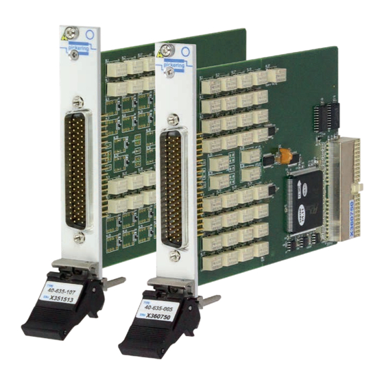
- Page 1 40-635A User Manual PXI Low Cost EMR Multiplexer Module pickeringtest.com Issue 1.1 February 2020...
- Page 2 © COPYRIGHT (2020) PICKERING INTERFACES. ALL RIGHTS RESERVED. No part of this publication may be reproduced, transmitted, transcribed, translated or stored in any form, or by any means without the written permission of Pickering Interfaces. Technical details contained within this publication are subject to change without notice.
- Page 3 Pickering Interfaces strives to fulfil all relevant environmental laws and regulations and reduce wastes and releases to the environment. Pickering Interfaces aims to design and operate products in a way that protects the environment and the health and safety of its employees, customers and the public. Pickering Interfaces endeavours to develop and manufacture products that can be produced, distributed, used and recycled, or disposed of, in a safe and environmentally friendly manner.
-
Page 4: Product Safety
PRODUCT SAFETY SAFETY SYMBOLS The following safety symbols may be used on the product and throughout the product documentation. MEANING / DESCRIPTION SYMBOL PROTECTIVE EARTH (GROUND) To identify any terminal which is intended for connection to an external conductor for protection against electric shock in case of a fault, or the terminal of a protective earth (ground) electrode. -
Page 5: Table Of Contents
Pre Operation Checks ............3.1 Hardware Installation ............3.2 Software Installation .............3.2 Testing Operation ..............3.3 Section 4 Programming Guide ..............4.1 Programming Options For Pickering PXI Modules ....4.1 Module Architecture..............4.2 Programming The Module ............4.20 Section 5 Connector Information ..............5.1 Section 6 Trouble Shooting .................6.1 Section 7 Maintenance Information ............7.1... - Page 6 THIS PAGE INTENTIONALLY BLANK LOW COST EMR MULTIPLEXER MODULE 40-635A Page (VI)
-
Page 7: Warnings And Cautions
Not to be used in safety critical circuits, refer to the Pickering Interfaces’ terms & conditions of sale. This module must not be used for the switching of Mains Circuits. For the switching of voltages up to the module’s full specification, Secondary Circuit power supplies and the Device Under Test must... - Page 8 CAUTION - PRODUCT DOCUMENTATION SYMBOL Suitably qualified & trained users should ensure that the accompanying documentation is fully read and understood before attempting to install or operate the product. SAFETY INSTRUCTIONS SAFETY INSTRUCTIONS All cleaning and servicing requires the equipment to be isolated and disconnected from the power source and user I/O signals (refer to the Maintenance Section).
-
Page 9: Technical Specification
SECTION 1 - TECHNICAL SPECIFICATION pickering PXI 2 Amp Multiplexer 40-635A SECTION 1 - TECHNICAL SPECIFICATION • Single: 64-Channel 1-Pole, 32-Channel 2-Pole, 16-Channel 4-Pole, 8-Channel 8-Pole • Dual: 32-Channel 1-Pole, 16-Channel 2-Pole, 8-Channel 4-Pole • Quad: 16-Channel 1-Pole, 8-Channel 2-Pole •... - Page 10 SECTION 1 - TECHNICAL SPECIFICATION pickering Overview 2 Amp Multiplexer – 40-635A C1.1 C1.2 C1.3 C1.4 C1.5 C1.6 C1.7 BANK 1 C1.8 C1.1 C1.2 C1.3 C1.4 16.1 16.2 BANK 2 16.3 16.4 40-635A-005 40-635A-003 40-635A-004 Dual 32-Channel 1-Pole MUX Single 16-Channel 4-Pole MUX Single 8-Channel 8-Pole MUX C1.1...
- Page 11 SECTION 1 - TECHNICAL SPECIFICATION pickering Overview 2 Amp Multiplexer – 40-635A C1.1 C1.2 C1.3 C1.4 C1.5 C1.6 C1.7 C1.8 C1.1 40-635A-101 C1.2 32-Channel 1-Pole MUX C1.3 C1.4 C1.1 C1.2 40-635A-104 40-635A-103 Single 4-Channel 8-Pole MUX Single 8-Channel 4-Pole MUX 16.1...
- Page 12 SECTION 1 - TECHNICAL SPECIFICATION Specifications pickering 2 Amp Multiplexer – 40-635A RF Specification - In a 50Ω System Relay Type The 40-635A is fitted with electro-mechanical relays with palladium- Bandwidth (-3dB): 15MHz (40-635A-001) 15MHz (40-635A-002) ruthenium gold covered contacts. A Spare Relay is built onto the...
- Page 13 Model Variant Order Code Selection Product Customization Single Single 16-Channel, 2-Pole 40-635A-102 Pickering PXI modules are designed and manufactured on our own Single Single 8-Channel, 4-Pole 40-635A-103 flexible manufacturing lines, giving complete product control and Single Single 4-Channel, 8-Pole 40-635A-104 enabling simple customization to meet very specific requirements.
- Page 14 We provide a full range of supporting cable and connector solutions for all our switching products—20 connector families with 1200+ products. We offer everything from simple mating connectors to complex cables assemblies and terminal blocks. All assemblies are manufactured by Pickering and are guaranteed to mechanically and electrically mate to our modules. Connectors & Backshells...
- Page 15 2 Amp Multiplexer – 40-635A Programming Pickering provide kernel, IVI and VISA (NI & Keysight) drivers which are compatible with all Microsoft supported versions of Windows and popular older versions. For a list of all supporting operating systems, please see: pickeringtest.com/os...
- Page 16 SECTION 1 - TECHNICAL SPECIFICATION pickering THIS PAGE INTENTIONALLY BLANK LOW COST EMR MULTIPLEXER MODULE 40-635A Page 1.8...
-
Page 17: Functional Description
SECTION 2 - TECHNICAL DESCRIPTION pickering SECTION 2 - TECHNICAL DESCRIPTION FUNCTIONAL DESCRIPTION A functional block diagram is provided in Figure 2.1. The Multiplexer Module 40-635A is powered by a +5V input via Compact PCI connector J1. The interface to the user test equipment is via the front panel mounted 78-pin D-type connector, J2. - Page 18 SECTION 2 - TECHNICAL DESCRIPTION pickering THIS PAGE INTENTIONALLY BLANK LOW COST EMR MULTIPLEXER MODULE 40-635A Page 2.2...
-
Page 19: Installation
Modular products require installation in a suitable PXI/LXI chassis. The module is designed for indoor use only. PREOPERATION CHECKS (UNPACKING) 1. Check the module for transport damage and report any damage immediately to Pickering Interfaces. Do not attempt to install the product if any damage is evident. -
Page 20: Hardware Installation
For a system comprising more than one chassis, turn ON the last chassis in the system followed by the penultimate, etc, and finally turn ON the external controller or chassis containing the system controller. 9. For Pickering Interfaces modular LXI installation there is no requirement to use any particular power up sequence. -
Page 21: Testing Operation
Figure 3.2 - General Soft Front Panel Icon A selector panel will appear, listing all installed Pickering PCI, PXI or LXI switch cards and resistor cards. Click on the card you wish to control, and a graphical control panel is presented allowing operation of the card. - Page 22 SECTION 3 - INSTALLATION pickering THIS PAGE INTENTIONALLY BLANK LOW COST EMR MULTIPLEXER MODULE 40-635A Page 3.4...
-
Page 23: Programming Guide
SECTION 4 - PROGRAMMING GUIDE PROGRAMMING OPTIONS FOR PICKERING INTERFACES PXI MODULES For information on the installation and use of drivers and the programming of Pickering’s products in various software environments, please refer to the Software User Manual. This is available as a download from: https://www.pickeringtest.com/support/software-drivers-and-downloads... -
Page 24: Module Architecture
SECTION 4 - PROGRAMMING GUIDE pickering MODULE ARCHITECTURE The 40-635A module is an array of up to 36 DPDT relays factory configured in to one of 18 different multiplexer configurations. In the default state, all multiplexer channels are open circuit. Energising a particular channel creates a signal path between the common terminal(s) and the corresponding channel terminal(s). - Page 25 SECTION 4 - PROGRAMMING GUIDE pickering CH1.1 CH1.2 CH2.1 40-635A-002 CH2.2 COM1.1 Single 32-Channel COM1.2 2-Pole Multiplexer CH32.1 CH32.2 Programming Bit / Signal Path Table For Single 32-Channel 2-Pole Multiplexer (40-635A-002) Sub- IVI Channel Sub- IVI Channel Signal Path Signal Path...
- Page 26 SECTION 4 - PROGRAMMING GUIDE pickering CH1.1 CH1.2 CH1.3 CH1.4 CH2.1 CH2.2 COM1.1 40-635A-003 CH2.3 COM1.2 Single 16-Channel CH2.4 COM1.3 4-Pole Multiplexer COM1.4 CH16.1 CH16.2 CH16.3 CH16.4 Programming Bit / Signal Path Table For Single 16-Channel 4-Pole Multiplexer (40-635A-003) Sub-...
- Page 27 SECTION 4 - PROGRAMMING GUIDE pickering COM1.1 CH1.1 COM1.2 CH1.2 COM1.3 CH1.3 COM1.4 CH1.4 COM1.5 CH1.5 COM1.6 CH1.6 COM1.7 CH1.7 COM1.8 CH1.8 40-635A-004 Single 8-Channel CH8.1 8-Pole Multiplexer CH8.2 CH8.3 CH8.4 CH8.5 CH8.6 CH8.7 CH8.8 Programming Bit / Signal Path Table For Single 8-Channel 8-Pole Multiplexer (40-635A-004)
- Page 28 SECTION 4 - PROGRAMMING GUIDE pickering CH101 CH102 CH103 COM1 BANK 1 CH132 40-635A-005 Dual 32-Channel CH201 1-Pole Multiplexer CH202 CH203 COM2 BANK 2 CH232 Programming Bit / Signal Path Table For Dual 32-Channel 1-Pole Multiplexer (40-635A-005) Sub- IVI Channel...
- Page 29 SECTION 4 - PROGRAMMING GUIDE pickering CH101.1 CH201.1 CH101.2 CH201.2 40-635A-006 CH102.1 CH202.1 CH102.2 CH202.2 Dual 16-Channel COM1.1 COM2.1 2-Pole Multiplexer COM1.2 COM2.2 BANK 1 BANK 2 CH116.1 CH216.1 CH116.2 CH216.2 Programming Bit / Signal Path Table For Dual 16-Channel 2-Pole Multiplexer (40-635A-006)
- Page 30 SECTION 4 - PROGRAMMING GUIDE pickering CH101.1 CH201.1 CH101.2 CH201.2 CH101.3 CH201.3 CH101.4 CH201.4 CH102.1 CH202.1 CH102.2 CH202.2 COM1.1 COM2.1 40-635A-007 CH102.3 CH202.3 COM1.2 COM2.2 Dual 8-Channel CH102.4 CH202.4 COM1.3 COM2.3 4-Pole Multiplexer COM1.4 COM2.4 CH108.1 CH208.1 BANK 1 BANK 2 CH108.2...
- Page 31 SECTION 4 - PROGRAMMING GUIDE pickering CH101 CH201 CH102 CH202 CH103 CH203 COM1 COM2 BANK 1 BANK 2 CH116 CH216 40-635A-008 Quad 16-Channel CH301 CH401 1-Pole Multiplexer CH302 CH402 CH303 CH403 COM3 COM4 BANK 3 BANK 4 CH316 CH416 Programming Bit / Signal Path Table For Quad 16-Channel 1-Pole Multiplexer (40-635A-008)
- Page 32 SECTION 4 - PROGRAMMING GUIDE pickering CH101.1 CH201.1 CH101.2 CH201.2 CH201.1 CH202.1 CH201.2 CH202.2 COM1.1 COM2.1 COM1.2 COM2.2 BANK 1 BANK 2 CH801.1 CH208.1 CH801.2 CH208.2 40-635A-009 Quad 8-Channel CH301.1 CH401.1 2-Pole Multiplexer CH301.2 CH401.2 CH302.1 CH402.1 CH302.2 CH402.2 COM3.1 COM4.1...
- Page 33 SECTION 4 - PROGRAMMING GUIDE pickering 40-635A-101: COM1 Single 32-Channel 1-Pole Multiplexer CH32 Programming Bit / Signal Path Table For Single 32-Channel 1-Pole Multiplexer (40-635A-101) Sub-Unit Signal Path IVI Channel Names COM1 to CH1 COM1 to CH2 COM1 to CH3...
- Page 34 SECTION 4 - PROGRAMMING GUIDE pickering CH1.1 CH1.2 CH2.1 40-635A-102 CH2.2 COM1.1 Single 16-Channel COM1.2 2-Pole Multiplexer CH16.1 CH16.2 Programming Bit / Signal Path Table For Single 16-Channel 2-Pole Multiplexer (40-635A-102) Sub-Unit Signal Path IVI Channel Names COM1.1 to CH1.1 COM1.2 to CH1.2...
- Page 35 SECTION 4 - PROGRAMMING GUIDE pickering CH1.1 CH1.2 CH1.3 CH1.4 CH2.1 CH2.2 COM1.1 40-635A-103 CH2.3 COM1.2 Single 8-Channel CH2.4 COM1.3 4-Pole Multiplexer COM1.4 CH8.1 CH8.2 CH8.3 CH8.4 Programming Bit / Signal Path Table For Single 8-Channel 4-Pole Multiplexer (40-635A-103) Sub-Unit...
- Page 36 SECTION 4 - PROGRAMMING GUIDE pickering COM1.1 CH1.1 COM1.2 CH1.2 COM1.3 CH1.3 COM1.4 CH1.4 COM1.5 CH1.5 COM1.6 CH1.6 COM1.7 CH1.7 COM1.8 CH1.8 40-635A-104 Single 4-Channel CH4.1 8-Pole Multiplexer CH4.2 CH4.3 CH4.4 CH4.5 CH4.6 CH4.7 CH4.8 Programming Bit / Signal Path Table For...
- Page 37 SECTION 4 - PROGRAMMING GUIDE pickering CH101 CH102 CH103 COM1 BANK 1 CH116 40-635A-105 Dual 16-Channel CH201 1-Pole Multiplexer CH202 CH203 COM2 BANK 2 CH216 Programming Bit / Signal Path Table For Dual 16-Channel 1-Pole Multiplexer (40-635A-105) Sub-Unit Signal Path...
- Page 38 SECTION 4 - PROGRAMMING GUIDE pickering CH101.1 CH201.1 CH101.2 CH201.2 40-635A-106 CH102.1 CH202.1 CH102.2 CH202.2 Dual 8-Channel COM1.1 COM2.1 2-Pole Multiplexer COM1.2 COM2.2 BANK 1 BANK 2 CH108.1 CH208.1 CH108.2 CH208.2 Programming Bit / Signal Path Table For Dual 8-Channel 2-Pole Multiplexer (40-635A-106)
- Page 39 SECTION 4 - PROGRAMMING GUIDE pickering COM1.1 CH101.1 COM2.1 CH201.1 COM1.2 CH101.2 COM2.2 CH201.2 COM1.3 CH101.3 COM2.3 CH201.3 COM1.4 CH101.4 COM2.4 CH201.4 40-635A-107 Dual 4-Channel 4-Pole Multiplexer CH104.1 CH204.1 BANK 1 BANK 2 CH104.2 CH204.2 CH104.3 CH204.3 CH104.4 CH204.4 Programming Bit / Signal Path Table For...
- Page 40 SECTION 4 - PROGRAMMING GUIDE pickering CH101 CH201 CH102 CH202 COM1 COM2 BANK 1 BANK 2 40-635A-108 CH108 CH208 Quad 8-Channel 1-Pole Multiplexer CH301 CH401 CH302 CH402 COM3 COM4 BANK 3 BANK 4 CH308 CH408 Programming Bit / Signal Path Table For...
- Page 41 SECTION 4 - PROGRAMMING GUIDE pickering CH101.1 CH201.1 CH101.2 COM1.1 CH201.2 COM2.1 COM1.2 COM2.2 BANK 1 CH104.1 BANK 2 CH204.1 CH104.2 40-635A-109 CH204.2 Quad 4-Channel CH301.1 CH401.1 2-Pole Multiplexer CH301.2 CH401.2 COM3.1 COM4.1 COM3.2 COM4.2 BANK 3 BANK 4 CH304.1 CH404.1...
-
Page 42: Programming The Module
SECTION 4 - PROGRAMMING GUIDE pickering PROGRAMMING THE MODULE Here are examples of using the drivers with the 40-635A-001 (64-Channel-1 Pole) Multiplexer module. Other modules in the range operate in a similar way but the sub-units / bits may vary. -
Page 43: Connector Information
SECTION 5 - CONNECTOR INFORMATION pickering SECTION 5 - CONNECTOR INFORMATION CH34 CH33 CH36 CH35 CH38 CH37 CH40 CH39 CH42 CH10 CH41 CH44 CH12 CH43 CH11 CH46 CH14 CH45 CH13 CH48 CH16 CH47 CH15 COM1 COM1 CH50 CH18 CH49 CH17... - Page 44 SECTION 5 - CONNECTOR INFORMATION pickering CH17.2 CH1.2 CH17.1 CH1.1 CH18.2 CH2.2 CH18.1 CH2.1 CH19.2 CH3.2 CH19.1 CH3.1 CH20.2 CH4.2 CH20.1 CH4.1 CH1.1 CH21.2 CH5.2 CH21.1 CH5.1 CH1.2 CH22.2 CH6.2 CH22.1 CH6.1 CH23.2 CH7.2 CH23.1 CH7.1 CH2.1 CH24.2 CH8.2 CH24.1 CH8.1...
- Page 45 SECTION 5 - CONNECTOR INFORMATION pickering CH1.4 CH1.2 CH1.1 CH1.3 CH1.1 CH2.4 CH2.2 CH2.3 CH2.1 CH1.2 CH3.4 CH3.2 CH3.3 CH3.1 CH4.4 CH1.3 CH4.2 CH4.3 CH4.1 CH5.4 CH5.2 CH1.4 CH5.3 CH5.1 CH6.4 CH6.2 CH6.3 CH6.1 CH2.1 CH7.4 CH7.2 CH7.3 CH7.1 CH2.2 CH8.4...
- Page 46 SECTION 5 - CONNECTOR INFORMATION pickering COM1.1 CH1.1 CH1.6 CH1.2 CH1.5 CH1.1 COM1.2 CH1.2 CH2.6 CH2.2 CH2.5 CH2.1 COM1.3 CH1.3 CH3.6 CH3.2 CH3.5 CH3.1 COM1.4 CH1.4 CH4.6 CH4.2 CH4.5 CH4.1 COM1.5 CH1.5 CH5.6 CH5.2 CH5.5 CH5.1 CH6.6 COM1.6 CH1.6 CH6.2 CH6.5...
- Page 47 SECTION 5 - CONNECTOR INFORMATION pickering CH202 CH102 CH101 CH201 CH204 CH104 CH101 CH203 CH103 CH206 CH106 CH205 CH105 CH102 CH208 CH108 CH207 CH107 CH210 CH110 CH209 CH109 CH103 CH212 CH112 COM1 CH211 CH111 CH214 CH114 CH213 CH113 CH216 CH116...
- Page 48 SECTION 5 - CONNECTOR INFORMATION pickering CH101.1 CH201.2 CH101.2 CH201.1 CH101.1 CH101.2 CH202.2 CH102.2 CH202.1 CH102.1 CH203.2 CH103.2 CH102.1 CH103.1 CH203.1 CH204.2 CH104.2 CH102.2 CH104.1 CH204.1 CH205.2 CH105.2 COM1.1 CH205.1 CH105.1 CH206.2 CH106.2 COM1.2 CH206.1 CH106.1 CH207.2 CH107.2 CH207.1 CH107.1 CH208.2...
- Page 49 SECTION 5 - CONNECTOR INFORMATION pickering CH101.1 CH101.2 CH101.3 CH101.4 CH102.1 CH102.2 COM1.1 CH102.3 CH201.2 CH101.2 COM1.2 CH201.1 CH101.1 CH102.4 CH202.2 CH102.2 COM1.3 CH202.1 CH102.1 CH203.2 CH103.2 COM1.4 CH103.1 CH203.1 CH204.2 CH104.2 CH104.1 CH204.1 CH205.2 CH105.2 CH108.1 CH205.1 CH105.1 CH206.2 CH106.2...
- Page 50 SECTION 5 - CONNECTOR INFORMATION pickering CH101 CH102 CH103 COM1 BANK 1 CH116 CH201 CH302 CH102 CH301 CH101 CH304 CH104 CH202 CH303 CH103 CH306 CH106 CH305 CH105 CH203 CH308 CH108 COM2 CH307 CH107 CH310 CH110 CH109 CH309 CH312 CH112 BANK 2...
- Page 51 SECTION 5 - CONNECTOR INFORMATION pickering CH101.1 CH101.2 CH102.1 CH102.2 COM1.1 COM1.2 BANK 1 CH108.1 CH108.2 CH201.1 CH201.2 CH301.2 CH101.2 CH301.1 CH101.1 CH202.1 CH302.2 CH102.2 CH302.1 CH102.1 CH202.2 CH303.2 COM2.1 CH103.2 CH303.1 CH103.1 COM2.2 CH304.2 CH104.2 CH304.1 CH104.1 CH305.2 CH105.2 CH105.1...
- Page 52 SECTION 5 - CONNECTOR INFORMATION pickering CH18 CH17 CH20 CH19 CH22 CH21 CH24 CH23 COM1 COM1 CH26 CH10 CH25 CH28 CH12 CH27 CH11 CH32 CH30 CH14 CH29 CH13 CH32 CH16 CH15 CH31 Single 32-Channel 1-Pole Multiplexer FP_GND Figure 5.10 - 40-635A-101 Pinout...
- Page 53 SECTION 5 - CONNECTOR INFORMATION pickering CH9.2 CH1.2 CH9.1 CH1.1 CH10.2 CH2.2 CH10.1 CH2.1 CH11.2 CH3.2 CH11.1 CH3.1 CH12.2 CH4.2 CH1.1 CH12.1 CH4.1 CH1.2 CH2.1 CH2.2 COM1.1 COM1.1 COM1.2 COM1.2 CH13.2 CH5.2 CH13.1 CH5.1 CH16.1 CH14.2 CH6.2 CH14.1 CH6.1 CH16.2 CH15.2...
- Page 54 SECTION 5 - CONNECTOR INFORMATION pickering CH1.4 CH1.2 CH1.3 CH1.1 CH2.4 CH2.2 CH2.3 CH2.1 CH1.1 CH3.4 CH3.2 CH3.3 CH3.1 CH1.2 CH4.4 CH4.2 CH4.3 CH4.1 CH1.3 CH1.4 CH2.1 CH2.2 COM1.1 CH2.3 COM1.2 COM1.1 COM1.3 CH2.4 COM1.3 COM1.2 COM1.4 COM1.4 CH5.4 CH5.2 CH5.3...
- Page 55 SECTION 5 - CONNECTOR INFORMATION pickering CH1.6 CH1.2 CH1.5 CH1.1 CH2.6 CH2.2 COM1.1 CH1.1 CH2.5 CH2.1 CH3.6 CH3.2 COM1.2 CH1.2 CH3.5 CH3.1 COM1.3 CH1.3 CH4.6 CH4.2 CH4.5 CH4.1 COM1.4 CH1.4 COM1.5 CH1.5 COM1.6 CH1.6 COM1.7 CH1.7 COM1.8 CH1.8 COM1.7 COM1.3 COM1.1...
- Page 56 SECTION 5 - CONNECTOR INFORMATION pickering CH202 CH102 CH201 CH101 CH204 CH101 CH104 CH203 CH103 CH206 CH106 CH102 CH205 CH105 CH208 CH108 CH207 CH107 CH103 COM1 BANK 1 CH116 COM1 COM2 CH201 CH210 CH110 CH202 CH209 CH109 CH212 CH112 CH211...
- Page 57 SECTION 5 - CONNECTOR INFORMATION pickering CH101.1 CH201.2 CH101.2 CH101.2 CH201.1 CH101.1 CH202.2 CH102.2 CH102.1 CH202.1 CH102.1 CH203.2 CH103.2 CH203.1 CH103.1 CH102.2 CH204.2 CH104.2 COM1.1 CH204.1 CH104.1 COM1.2 BANK 1 CH108.1 CH108.2 COM1.1 COM2.1 COM1.2 COM2.2 CH201.1 CH205.2 CH105.2 CH205.1 CH105.1...
- Page 58 SECTION 5 - CONNECTOR INFORMATION pickering COM1.1 CH101.1 COM1.2 CH101.2 CH201.2 CH101.2 COM1.3 CH101.3 CH201.1 CH101.1 CH202.2 COM1.4 CH101.4 CH102.2 CH102.1 CH202.1 CH203.2 CH103.2 CH203.1 CH103.1 CH204.2 CH104.2 CH204.1 CH104.1 CH104.1 BANK 1 CH104.2 CH104.3 CH104.4 COM2.3 COM1.3 COM1.1 COM2.1 COM2.1...
- Page 59 SECTION 5 - CONNECTOR INFORMATION pickering CH101 CH102 COM1 BANK 1 CH108 CH302 CH102 CH301 CH101 CH201 CH304 CH104 CH303 CH103 CH306 CH106 CH202 CH305 CH105 COM2 CH308 CH108 CH307 CH107 BANK 2 CH208 CH301 COM4 COM2 CH302 COM1 COM3...
- Page 60 SECTION 5 - CONNECTOR INFORMATION pickering CH101.1 CH101.2 COM1.1 COM1.2 BANK 1 CH104.1 CH104.2 CH301.2 CH101.2 CH301.1 CH101.1 CH201.1 CH302.2 CH102.2 CH102.1 CH302.1 CH201.2 CH303.2 CH103.2 COM2.1 CH303.1 CH103.1 CH304.2 CH104.2 COM2.2 CH304.1 CH104.1 BANK 2 CH204.1 CH204.2 COM4.1 COM2.1 CH301.1...
-
Page 61: Trouble Shooting
PCI configuration, highlighting any potential configuration problems. Specific details of all installed Pickering switch cards are included. All the installed Pickering switch cards should be listed in the “Pilpxi information” section - if one or more cards is missing it may be possible to determine the reason by referring to the PCI configuration dump contained in the report, but interpretation of this information is far from straightforward, and the best course is to contact Pickering support: support@pickeringtest.com, if possible... - Page 62 SECTION 6 - TROUBLE SHOOTING pickering THIS PAGE INTENTIONALLY BLANK LOW COST EMR MULTIPLEXER MODULE 40-635A Page 6.2...
-
Page 63: Maintenance Information
For PXI modules which are supported in one of Pickering Interfaces’ Modular LXI Chassis (such as the 60-102B and 60-103B) no module software update is required. If the module was introduced after the LXI chassis was manufactured the module may not be recognized, in this case the chassis firmware may need upgrading. - Page 64 SECTION 7 - MAINTENANCE INFORMATION pickering Table 7.1 - 40-635A-001: Relay Numbering Relay Table For Single 64-Channel 1-Pole Multiplexer (40-635A-001) Relays Relays Signal Path Signal Path Energized Energized COM1 to CH1 ─ COM1 to CH33 RL17 ─ COM1 to CH2...
- Page 65 SECTION 7 - MAINTENANCE INFORMATION pickering Table 7.2 - 40-635A-002: Relay Numbering Relay Table For Single 32-Channel 2-Pole Multiplexer (40-635A-002) Relays Relays Signal Path Signal Path Energized Energized COM1.1 to CH1.1 ─ COM1.1 to CH17.1 RL17 ─ COM1.2 to CH1.2 ─...
- Page 66 SECTION 7 - MAINTENANCE INFORMATION pickering Table 7.3 - 40-635A-003: Relay Numbering Relay Table For Single 16-Channel 4-Pole Multiplexer (40-635A-003) Relays Relays Signal Path Signal Path Energized Energized COM1.1 to CH1.1 ─ COM1.1 to CH9.1 ─ COM1.2 to CH1.2 ─...
- Page 67 SECTION 7 - MAINTENANCE INFORMATION pickering Table 7.4 - 40-635A-004: Relay Numbering Relay Table For Single 8-Channel 8-Pole Multiplexer (40-635A-004) Relays Relays Signal Path Signal Path Energized Energized COM1.1 to CH1.1 ─ COM1.1 to CH5.1 ─ COM1.2 to CH1.2 ─...
- Page 68 SECTION 7 - MAINTENANCE INFORMATION pickering Table 7.5 - 40-635A-005: Relay Numbering Relay Table For Dual 32-Channel 1-Pole Multiplexer (40-635A-005) Relays Relays Bank Signal Path Bank Signal Path Energized Energized COM1 to CH101 ─ COM2 to CH201 RL17 ─ COM1 to CH102...
- Page 69 SECTION 7 - MAINTENANCE INFORMATION pickering Table 7.6 - 40-635A-006: Relay Numbering Relay Table For Dual 16-Channel 2-Pole Multiplexer (40-635A-006) Relays Relays Bank Signal Path Bank Signal Path Energized Energized COM1.1 to CH101.1 ─ COM2.1 to CH201.1 RL17 ─ COM1.2 to CH101.2 ─...
- Page 70 SECTION 7 - MAINTENANCE INFORMATION pickering Table 7.7 - 40-635A-007: Relay Numbering Relay Table For Dual 8-Channel 4-Pole Multiplexer (40-635A-007) Relays Relays Bank Signal Path Bank Signal Path Energized Energized COM1.1 to CH101.1 ─ COM2.1 to CH201.1 RL17 ─ COM1.2 to CH101.2 ─...
- Page 71 SECTION 7 - MAINTENANCE INFORMATION pickering Table 7.8 - 40-635A-008: Relay Numbering Relay Table For Quad 16-Channel 1-Pole Multiplexer (40-635A-008) Relays Relays Bank Signal Path Bank Signal Path Energized Energized COM1 to CH101 ─ COM3 to CH301 RL17 ─ COM1 to CH102...
- Page 72 SECTION 7 - MAINTENANCE INFORMATION pickering Table 7.9 - 40-635A-009: Relay Numbering Relay Table For Quad 8-Channel 2-Pole Multiplexer (40-635A-009) Relays Relays Bank Signal Path Bank Signal Path Energized Energized COM1.1 to CH101.1 ─ COM3.1 to CH301.1 RL17 ─ COM1.2 to CH101.2 ─...
- Page 73 SECTION 7 - MAINTENANCE INFORMATION pickering Table 7.10 - 40-635A-101: Relay Numbering Relay Table For Single 32-Channel 1-Pole Multiplexer (40-635A-101) Relays Relays Signal Path Signal Path Energized Energized COM1 to CH1 ─ COM1 to CH17 RL17 ─ COM1 to CH2...
- Page 74 SECTION 7 - MAINTENANCE INFORMATION pickering Table 7.12 - 40-635A-103: Relay Numbering Relay Table For Single 8-Channel 4-Pole Multiplexer (40-635A-103) Relays Relays Signal Path Signal Path Energized Energized COM1.1 to CH1.1 ─ COM1.1 to CH5.1 ─ COM1.2 to CH1.2 ─...
- Page 75 SECTION 7 - MAINTENANCE INFORMATION pickering Table 7.14 - 40-635A-105: Relay Numbering Relay Table For Dual 16-Channel 1-Pole Multiplexer (40-635A-105) Relays Relays Bank Signal Path Bank Signal Path Energized Energized COM1 to CH101 ─ COM2 to CH201 RL17 ─ COM1 to CH102...
- Page 76 SECTION 7 - MAINTENANCE INFORMATION pickering Table 7.16 - 40-635A-107: Relay Numbering Relay Table For Dual 4-Channel 4-Pole Multiplexer (40-635A-107) Relays Relays Bank Signal Path Bank Signal Path Energized Energized COM1.1 to CH101.1 ─ COM2.1 to CH201.1 RL17 ─ COM1.2 to CH101.2 ─...
- Page 77 SECTION 7 - MAINTENANCE INFORMATION pickering Table 7.18 - 40-635A-109: Relay Numbering Relay Table For Quad 4-Channel 2-Pole Multiplexer (40-635A-109) Relays Relays Bank Signal Path Bank Signal Path Energized Energized COM1.1 to CH101.1 ─ COM3.1 to CH301.1 RL17 ─ COM1.2 to CH101.2 ─...
- Page 78 SECTION 7 - MAINTENANCE INFORMATION pickering RL17 RL18 SPARE RL19 RL20 RL21 RL22 RL23 RL24 RL33 RL35 RL34 RL36 RL10 RL25 RL26 RL11 RL12 RL27 RL28 RL13 RL14 RL29 RL30 RL15 RL16 RL31 RL32 Figure 7.1 - 40-635A Multiplexer Module: Relay Positions LOW COST EMR MULTIPLEXER MODULE 40-635A Page 7.16...
Need help?
Do you have a question about the PXI 40-635A and is the answer not in the manual?
Questions and answers