
Subscribe to Our Youtube Channel
Related Manuals for Pickering 4 784B Series


Summary of Contents for Pickering 4 784B Series
- Page 1 4x-784B User Manual PXI/PXIe Microwave Multiplexer Modules pickeringtest.com Issue 4.0, October 2023...
- Page 2 © Copyright (2023) Pickering Interfaces. All Rights Reserved. No part of this publication may be reproduced, transmitted, transcribed, translated or stored in any form, or by any means without the written permission of Pickering Interfaces. Technical details contained within this publication are subject to change without notice.
- Page 3 Pickering Interfaces strives to fulfil all relevant environmental laws and regulations and reduce wastes and releases to the environment. Pickering Interfaces aims to design and operate products in a way that protects the environment and the health and safety of its employees, customers and the public. Pickering Interfaces endeavours to develop and manufacture products that can be produced, distributed, used and recycled, or disposed of, in a safe and environmentally friendly manner.
-
Page 4: Product Safety
Product Safety Safety Symbols The following safety symbols may be used on the product and throughout the product documentation. Meaning/Description Symbol PROTECTIVE EARTH (GROUND) To identify any terminal which is intended for connection to an external conductor for protection against electric shock in case of a fault, or the terminal of a protective earth (ground) electrode. -
Page 5: Table Of Contents
Pre Operation Checks ..............................3.1 Hardware Installation ..............................3.2 Software Installation ..............................3.2 Testing Operation ................................3.3 Section 4 Programming Guide .................................4.1 Programming Options for Pickering PXI/PXIe Modules ..................4.1 Module Architecture ..............................4.2 Programming the Module ............................4.3 Using Pickering Drivers in LabVIEW ........................4.6 Section 5 Connector Information ..............................5.1 Section 6 Trouble Shooting ................................6.1... -
Page 6: Warnings And Cautions
Unused slots in the PXI/PXIe/LXI chassis are populated with blanking plates to prevent access to user I/O signals that may be present. Blanking panels are available to order from Pickering in a variety of slot widths. If the product is not used in this manner for example by using an extender card then additional care must be taken to avoid contact with exposed signals. -
Page 7: Technical Specification
PXI/PXIe Microwave Multiplexer Modules Section 1 - Technical Specification 4x-784B y Available as PXI or PXIe Modules y Single or Dual SP4T or SP6T Panel Mounted Multiplexer y Up To 3 Remote SP4T or SP6T Multiplexers From Single Slot Version y 50 Ω... - Page 8 Dual SP6T Triple SP4T Triple SP6T 4x-784B Multiplexer in Dual & Triple SP4T & SP6T Formats Remotely Mounted Microwave Multiplexer Versions 4x-784B pickering Single Slot Version 3 off Interface Cables 1.5m Length Remote Mount Microwave Multiplexers Remotely Mounted Microwave Multiplexers...
- Page 9 Specifications 4x-784B Section 1 - Technical Specification RF Specification - 6 GHz Versions Characteristic Impedance: 50 Ω Connectors: Bandwidth DC to 6 GHz Maximum RF Carry Power: 220 W (0-3 GHz) 150 W (3-6 GHz) Isolation: >80 dB (0-3 GHz) >70 dB (3-6 GHz) Insertion Loss: <0.2 dB (0-3 GHz)
- Page 10 Specifications 4x-784B Section 1 - Technical Specification RF Specification - 18 GHz Versions Characteristic Impedance: 50 Ω Connectors: Bandwidth DC to 18 GHz Maximum RF Carry Power: 220 W (0-3 GHz) 150 W (3-8 GHz) 120 W (8-12.4 GHz) 100 W (12.4-18 GHz) Isolation: >80 dB (0-3 GHz) Typical Insertion Loss (dB) - 18 GHz Versions...
- Page 11 Specifications 4x-784B Section 1 - Technical Specification RF Specification - 26.5 GHz Versions Characteristic Impedance: 50 Ω Connectors: DC to 26.5 GHz Bandwidth Maximum RF Carry Power: 220 W (0-3 GHz) 150 W (3-8 GHz) 120 W (8-12.4 GHz) 100 W (12.4-18 GHz) 40 W (18-26.5 GHz) Typical Insertion Loss (dB) - 26.5 GHz Versions Isolation:...
- Page 12 Specifications 4x-784B Section 1 - Technical Specification RF Specification - 40 GHz Versions Characteristic Impedance: 50 Ω Connectors: SMA 2.9 Bandwidth DC to 40 GHz Maximum RF Carry Power: 60 W (0-3 GHz) 35 W (3-8 GHz) 30 W (8-12.4 GHz) 25 W (12.4-18 GHz) 15 W (18-26.5 GHz) Typical Insertion Loss (dB) - 40 GHz Versions...
- Page 13 Specifications 4x-784B Section 1 - Technical Specification Switching Specification Mechanical Characteristics Front panel mounted multiplexers: Relay Manufacturer: Radiall Configuration: SP6T or SP4T Microwave • 40-784B single, dual and triple versions Multiplexer with 1, 2 or 3 - Dual slot 3U PXI (CompactPCI card) independent banks.
- Page 14 Spare SP4T 40 GHz relay with interface cable for 40-784B-143-E 40-784A-908-E Pickering can also offer mixed configurations of SP4T and Please contact the sales office for more information. SP6T multiplexers with a mix of bandwidths as outlined in the table below. Please contact the sales office with your requirements.
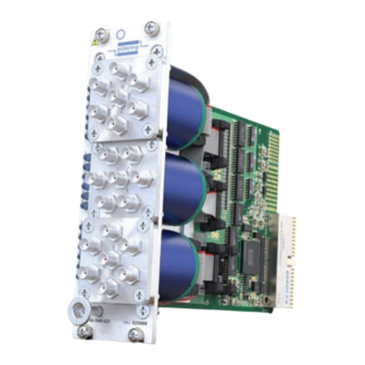
- Page 15 Side View of the PXI Triple Panel Mounted Microwave Multiplexer Product Customization Pickering modules are designed and manufactured on our own flexible manufacturing lines, giving complete product control and enabling simple customization to meet very specific requirements. Customization can include: •...
- Page 16 PXI/PXIe Microwave Multiplexer Modules 4x-784B Section 1 - Technical Specification The 4x-784B is part of a range of switching modules suitable for RF and microwave applications. Pickering’s Range of PXI & PXIe Microwave Switching Modules Switch Type Banks Frequency Range Model No.
-
Page 17: Technical Description
Section 2 - Technical Description Functional Description A functional block diagram is provided in Figure 2.1. The module is powered by +5V and +12V (PXI) or +3.3V and +12V (PXIe) supplies via PCI Bus connectors mounted on the mother board. The interface to the user test equipment is via the microwave relay’s SMA or SMA-2.9 connectors. -
Page 18: Installation
Modular products require installation in a suitable PXI/PXIe/LXI chassis. The module is designed for indoor use only. Pre-operation Checks (Unpacking) 1. Check the module for transport damage and report any damage immediately to Pickering Interfaces. Do not attempt to install the product if any damage is evident. -
Page 19: Hardware Installation
If you are not a LabVIEW user you should choose the “full” version, and once that has been installed run the LabVIEW Runtime Engine installer via the shortcut on the Programs>>Pickering menu. In the absence of LabVIEW the Runtime Engine is required to support the Pickering Test Panels application. -
Page 20: Testing Operation
Figure 3.2 - General Soft Front Panel Icon A selector panel will appear, listing all installed Pickering PCI, PXI/PXIe or LXI switch cards and resistor cards. Click on the card you wish to control, and a graphical control panel is presented allowing operation of the card. Panels can be opened simultaneously for all the installed cards. - Page 21 Section 4 - Programming Programming options for Pickering Interfaces PXI/PXIe Modules For information on the installation and use of drivers and the programming of Pickering’s products in various software environments, please refer to the Software User Manual. This is available as a download from: pickeringtest.com/support/software-drivers-and-downloads...
-
Page 22: Module Architecture
Section 4 - Programming Module Architecture The 40/42-784B is a 6 or 4-channel microwave multiplexer available with one, two or three banks either mounted on the front panel or remotely mounted and controlled via cables. In the default state, all channels are in the “off” position. Energising a particular channel number creates a signal path between the “Com”... -
Page 23: Programming The Module
Section 4 - Programming One sub-unit is used per bank to control the microwave multiplexer as shown below. Sub Unit Number Sub Unit Type Description MUX(6x1) + off SP6T Microwave Multiplexer Bank 1 MUX(6x1) + off SP6T Microwave Multiplexer Bank 2 MUX(6x1) + off SP6T Microwave Multiplexer Bank 3 MUX(4x1) + off... - Page 24 Section 4 - Programming Programming Bit / Signal Path Table For Triple Bank Versions 6-Channel Versions 4-Channel Versions Multiplexer Sub-Unit IVI Channel IVI Channel Bank Signal Path Signal Path Names Names Com to Ch1 comA chA1 Com to Ch1 comA chA1 Com to Ch2 comA...
- Page 25 Section 4 - Programming Using PIPX40 setChannelState ViUInt32 sub_unit = 1; // Select Bank 1 pipx40_setChannelState(vi, sub_unit, 1, VI_ON); // Enables the Com to Ch1 signal path pipx40_setChannelState(vi, sub_unit, 2, VI_ON); // Releases the Com to Ch1 signal path // and enables the Com to Ch2 signal path pipx40_setChannelState(vi, sub_unit, 2, VI_OFF);...
-
Page 26: Using Pickering Drivers In Labview
Section 4 - Programming Using Pickering Drivers In LabVIEW Most Pickering drivers include a LabVIEW wrapper to permit full operation of the Pickering product from the LabVIEW environment. These wrappers are normally installed to the current LabVIEW folder system during installation of the Pickering driver. - Page 27 Section 5 - Connectors pickering pickering pickering Bank 1 Bank 1 Bank 2 1 2 3 4 5 6 1 2 3 4 5 6 Bank 2 Bank 3 1 2 3 4 5 6 40/42-784B-0x1 40/42-784B-0x2 40/42-784B-0x3 Figure 5.1 - Microwave Multiplexer Module 40/42-784B: Connector Positions For Single, Dual and Triple SP6T Versions NOTE 1: Only the correct connector series should be mated with these modules.
- Page 28 Section 5 - Connectors pickering pickering pickering Bank 1 Bank 1 (Ch5) (Ch1) (Ch5) (Ch1) (Ch5) (Ch1) (Ch4) (Ch2) (Ch4) (Ch4) (Ch2) (Ch2) (Ch1) (Ch2) 1 2 3 1 2 3 Bank 2 Bank 2 (Ch4) (Ch5) (Ch5) (Ch1) (Ch4)
- Page 29 Section 5 - Connectors pickering pickering pickering 0-785B-522/752 40-785B Remote 40/42-784B-xx1-E 40/42-784B-xx2-E 40/42-784B-xx3-E Version (-E Suffix) Figure 5.3 - Microwave Multiplexer Module 40/42-784B Remote Mounted Versions: Connector Positions BANK 1 NOTE 1: Only the correct connector series should be mated with these modules. The...
-
Page 30: Trouble Shooting
PCI configuration, highlighting any potential configuration problems. Specific details of all installed Pickering switch cards are included. All the installed Pickering switch cards should be listed in the “Pilpxi information” section - if one or more cards is missing it may be possible to determine the reason by referring to the PCI configuration dump contained in the report, but interpretation of this information is far from straightforward, and the support@pickeringtest.com... -
Page 31: Maintenance Information
For PXI modules which are supported in one of Pickering Interfaces’ Modular LXI Chassis (such as the 60-102B and 60-103B) no module software update is required. If the module was introduced after the LXI chassis was manufactured the module may not be recognized, in this case the chassis firmware may need upgrading. -
Page 32: Appendix A Part Number List
Appendix A Part Number List The tables on the following pages show the complete list of part numbers for all the possible operating frequency, channel counts and bank number combinations for the 4x-784B microwave multiplexer range of modules. Product Order Codes - Dual Slot Panel Mounted Versions 6 GHz (SMA) 18 GHz (SMA) 26.5 GHz (SMA)
Need help?
Do you have a question about the 4 784B Series and is the answer not in the manual?
Questions and answers