Table of Contents
Advertisement
Quick Links
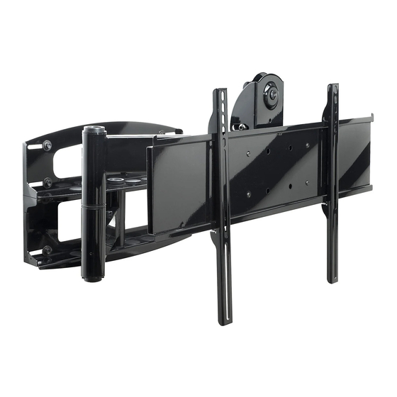
Installation and Assembly
Swivel Arm for 32" - 60" Plasma Screens
3215 W. North Ave. • Melrose Park, IL 60160 • (800) 729-0307 or (708) 865-8870 • Fax: (708) 865-2941 • www.peerlessmounts.com
- Universal Articulating
Models: PLA 60-UNL, PLA 60-UNL-S,
PLA 60-UNLP, PLA 60-UNLP-S,
PLAV 60-UNL, PLAV 60-UNL-S,
PLAV 60-UNLP, PLAV 60-UNLP-S
RTPLA 60-S
This product is UL Listed. It must be
installed by a qualified professional
R
installer.
Maximum UL Load Capacity: 175 lb (79 kg)
ISSUED: 06-05-06 SHEET #: 202-9141-3 08-17-06
Advertisement
Table of Contents

Related Manuals for PEERLESS PLA 60-UNL


Summary of Contents for PEERLESS PLA 60-UNL
- Page 1 Installation and Assembly - Universal Articulating Models: PLA 60-UNL, PLA 60-UNL-S, Swivel Arm for 32" - 60" Plasma Screens PLA 60-UNLP, PLA 60-UNLP-S, PLAV 60-UNL, PLAV 60-UNL-S, PLAV 60-UNLP, PLAV 60-UNLP-S RTPLA 60-S This product is UL Listed. It must be installed by a qualified professional installer.
-
Page 2: Wall Construction
Read instruction sheet before you start installation and assembly. WARNING • Do not begin to install your Peerless product until you have read and understood the instructions and warnings contained in this Installation Sheet. If you have any questions regarding any of the instructions or warnings, please call Peerless customer care at 1-800-729-0307. -
Page 3: Wall Mount Parts List
Wall Mount Parts List RTPLA 60-S PLA 60-UNL PLA 60-UNL-S PLAV 60-UNL PLAV 60-UNL-S Before you start make sure all parts listed are included with your product. PLA 60-UNLP PLA 60-UNLP-S PLAV 60-UNLP PLAV 60-UNLP-S DESCRIPTION QTY. PART # PART #... - Page 4 RTPLA 60-S Before you begin, make sure all parts shown are included with your product. PLA 60-UNL PLA 60-UNL-S PLA 60-UNLP PLA 60-UNLP-S Adapter Bracket Parts List PLAV 60-UNL PLAV 60-UNL-S PLAV 60-UNLP PLAV 60-UNLP-S Description Qty Part # Part #...
- Page 5 Security Adapter Bracket Fasteners M4 x 12 mm (6) M6 x 12 mm (4) M5 x 12 mm (4) M8 x 15 mm (6) 510-1079 520-1050 520-1064 M6 x 20 mm (4) 520-1068 520-9554 M5 x 25 mm (4) 520-1122 M8 x 25 mm (4) M4 x 25 mm (4) M6 x 25 mm (4)
-
Page 6: Installation To Wood Stud Wall
Place wall plate on wall as a template. The top mounting slots should be located .36" above the desired screen center for PLA 60-UNL, PLA 60-UNL-S, PLA 60-UNLP, PLA 60-UNLP-S and RTPLA 60- S and .43" below the desired screen center for PLAV 60-UNL, PLAV 60-UNL-S, PLAV 60-UNLP and PLAV 60- UNLP-S. - Page 7 The top mounting slots should anchor be located .36" above the desired screen center for PLA 60-UNL, PLA 60-UNL-S, PLA 60-UNLP, PLA 60-UNLP-S Drill hole(s) and insert anchor(s) and RTPLA 60-S and .43" below the desired screen...
- Page 8 WARNING • If you are uncertain that product is properly installed, call customer care. Note: There are five mounting positions. The center position is shown (right). Slide washer (J) over wall support arm axle (D). Next, insert plastic cap (N) into axle. Then, insert holding pin (M) into axle.
- Page 9 Attach two pieces of vinyl trim (E) to wall plate (A). Next, attach one piece of vinyl trim to bottom of swivel box on arm assembly (C). Insert one finishing cap (L) into each unused hole of wall plate (A). SWIVEL BOX Insert and tape carriage bolt (I) into top hole of pitch-roll assembly (B).
- Page 10 WARNING • Use an assistant or mechanical lifting equipment to safely lift and position the plasma TV. Insert two M10 screws (F) into swivel box on arm assembly (C) as shown. Leave approx. 1/4" of exposed thread. SWIVEL BOX .25" Hook tilt-roll assembly (B) onto M10 screws (F).
-
Page 11: Installing Adapter Brackets
Installing Adapter Brackets Refer to Screen Compatibility Chart to determine the proper fasteners to use. To prevent scratching the screen, set a cloth on a flat, level surface that will support the weight of the screen. Place screen face side down. If screen has knobs on the back, remove them to allow the adapter brackets to be attached. Place adapter brackets (BB or CC) on back of screen, align to holes, and center on back of screen as shown in figure 7.1. -
Page 12: Mounting And Removing Flat Panel Screen
Mounting and Removing Flat Panel Screen Refer to mount instruction sheet for attachment of adapter bracket to mount. Hook adapter brackets (BB or CC) onto adapter bracket (AA), then slowly swing screen in as shown. Turn screws clockwise at least six times to prevent screen from being removed as shown in detail 4. Tighten using allen wrench (DD). Screen can be adjusted horizontally if desired. - Page 13 13 of 13 ISSUED: 06-05-06 SHEET #: 202-9141-3 08-17-06 ©2006 Peerless Industries, Inc. All rights reserved. Peerless is a registered trademark of Peerless Industries, Inc. All other brand and product names are trademarks or registered trademarks of their respective owners.
Need help?
Do you have a question about the PLA 60-UNL and is the answer not in the manual?
Questions and answers