Table of Contents
Advertisement
Quick Links
Advertisement
Table of Contents

Related Manuals for PEERLESS PLAV 70


Summary of Contents for PEERLESS PLAV 70
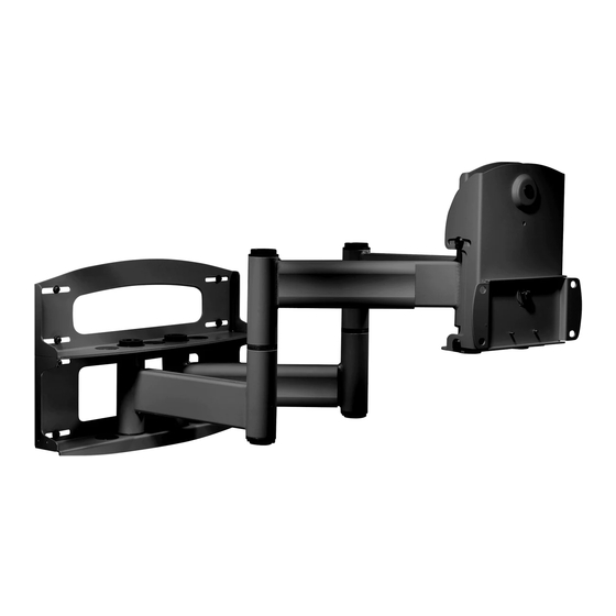
- Page 1 Installation and Assembly - Articulating Swivel Double-Arm Models: PLAV 70, PLAV 70-S for 42" - 71" Plasma Screens This product is UL Listed. It must be installed by a qualified professional installer. Maximum UL Load Capacity: 200 lb (91 kg)
-
Page 2: Wall Construction
Read instruction sheet before you start installation and assembly. WARNING • Do not begin to install your Peerless product until you have read and understood the instructions and warnings contained in this Installation Sheet. If you have any questions regarding any of the instructions or warnings, please call Peerless customer care at 1-800-729-0307. -
Page 3: Parts List
Before you start make sure all parts Parts List listed are included with your product. PLAV 70 PLAV 70-S DESCRIPTION QTY. PART # PART # A wall plate 201-1040 201-4040 B tilt-roll assembly 201-1042 201-4042 C arm assembly 201-1044 201-4044... -
Page 4: Installation To Wood Stud Wall
Installation to Wood Stud Wall WARNING • Installer must verify that the supporting surface will safely support the combined load of the equipment and all attached hardware and components. • Tighten wood screws so that wall plate is firmly attached, but do not overtighten. Overtightening can damage the screws, greatly reducing their holding power. - Page 5 Installation to Concrete Wall WARNING • Concrete must be 2000 psi density minimum. Lighter density concrete may not hold concrete anchor. • Make sure that the supporting surface will safely support the combined load of the equipment and all attached hardware and components.
- Page 6 WARNING • If you are uncertain that product is properly installed, call customer care. Note: There are three mounting positions. The center position is shown right. Arm assemblies must be mounted with one mounting hole separating them. Slide washers (J) over wall support arm axles (D).
- Page 7 Attach two pieces of vinyl trim (E) to wall plate (A). Next, attach one piece of vinyl trim to bottom of swivel box on arm assembly (C). Insert one finishing cap (L) into each unused hole of wall plate (A). SWIVEL BOX NOTE: Refer to adapter bracket instruction sheet for attachment of adapter bracket to plasma before proceeding with step 5.
- Page 8 WARNING • Use an assistant or mechanical lifting equipment to safely lift and position the plasma TV. Insert two M10 screws (F) into swivel box on arm assembly (C) as shown. Leave approx. 1/4" of exposed thread. SWIVEL BOX .25" Hook tilt-roll assembly (B) onto M10 screws (F).
- Page 9 Depending on the specific size & weight of the plasma, If it is too difficult to adjust roll of plasma, loosen articulating swing arm may be angled at different screws shown in figure 7.1 using a phillips screw- positions, causing plasma to appear to lean sideways driver.
Need help?
Do you have a question about the PLAV 70 and is the answer not in the manual?
Questions and answers