Advertisement
Table of Contents
- 1 Table of Contents
- 2 Parts List
- 3 Installation To Wood Joist Or Wood Beam Ceilings
- 4 Installation To Concrete Ceilings
- 5 Flush Mount Application
- 6 Installation To Extension Columns
- 7 Attaching Adapter Plate To Projector
- 8 Attaching Adapter Plate To Projector Mount, Projector Alignment
- Download this manual
Installation and Assembly Manual:
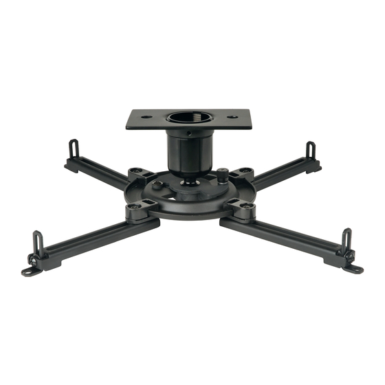
Vector Pro II™
Models: PJF2-UNV, PJF2-UNV-S
AEC*,
Compatible
ENG
EXT*,
model/series*
ADD*,
ACC500*,
CMJ400*,
DCT100,
DCS200,
CMJ500R1.
Visit the Peerless Web Site at www.peerless-av.com
Maximum UL Load Capacity: 50 lb (27 kg)
1 of 9
This product is intended for use with UL
Listed products and must be installed
by a qualified professional installer.
R
ISSUED: 01-14-09 SHEET #: 056-9018-3 11-10-16
For customer care call 1-800-865-2112.
Advertisement
Table of Contents

Related Manuals for PEERLESS PJF2-UNV


Summary of Contents for PEERLESS PJF2-UNV
- Page 1 AEC*, Compatible EXT*, model/series* ADD*, ACC500*, CMJ400*, Maximum UL Load Capacity: 50 lb (27 kg) DCT100, DCS200, CMJ500R1. 1 of 9 ISSUED: 01-14-09 SHEET #: 056-9018-3 11-10-16 Visit the Peerless Web Site at www.peerless-av.com For customer care call 1-800-865-2112.
-
Page 2: Table Of Contents
Parts List.................................... 3 Installation to Wood Joist or Wood Beam Ceilings ......................4 Installation to Concrete Ceilings ............................5 Flush Mount Application ..............................6 Installation to Extension Columns ............................. 7 Attaching Adapter Plate to Projector..........................8 Attaching Adapter Plate to Projector Mount, Projector Alignment ..................9 2 of 9 ISSUED: 01-14-09 SHEET #: 056-9018-3 11-10-16 Visit the Peerless Web Site at www.peerless-av.com For customer care call 1-800-865-2112. -
Page 3: Parts List
560-1097 560-1097 U 4mm security allen wrench 560-9646 560-9646 V M5 x 20mm serrated washer head socket pin screw 510-1065 510-2065 Note: Actual parts may appear slightly different than illustrated. 3 of 9 ISSUED: 01-14-09 SHEET #: 056-9018-3 11-10-16 Visit the Peerless Web Site at www.peerless-av.com For customer care call 1-800-865-2112. -
Page 4: Installation To Wood Joist Or Wood Beam Ceilings
IMPORTANT: Be sure to drill holes into the joist CENTER! For Optional Cord Management, install two spacers (J) between ceiling WOOD JOIST plate (C) and ceiling. CEILING 4 of 9 ISSUED: 01-14-09 SHEET #: 056-9018-3 11-10-16 Visit the Peerless Web Site at www.peerless-av.com For customer care call 1-800-865-2112. -
Page 5: Installation To Concrete Ceilings
• When installing Peerless ceiling mounts on a concrete ceiling, the ceiling must be at least 8" thick with a minimum compressive strength of 2000 psi. • Make sure that the supporting surface will safely support the combined load of the equipment and all attached hard- ware and components. • Never exceed the Maximum Load Capacity of 50 lb (27 kg). Installation to Concrete Ceilings CONCRETE CEILING Use only PEERLESS ACC233 concrete anchors (sold separately). Drill two 1/4" (6 mm) dia. holes to a minimum depth of 2.5" (64 mm). Attach ceiling plate (C) using two concrete anchors and #14 x 2.5" wood screws (H) as shown in concrete Illustration A and 1, 2, and 3 (below). Tighten all fasteners. anchor IMPORTANT: It is the responsibility of the installer to... -
Page 6: Flush Mount Application
Screw ball and socket mount (A) into ceiling plate (C) as shown in figure 3.1 (minimum 5 turns). Align the notch with one of the four holes of the ceiling plate (C) and secure ball and socket mount (A) with a M5 x 10 mm socket pin screw (E) using security allen wrench (U) as shown in figure 3.2 NOTE: Slotted set screw (L) is used to jam against the threads of the ball and socket mount to prevent any excess movement of the ball and socket mount (A). Do not overtighten screw; overtightening screw will damage threads making it difficult to separate the products. Skip to step 5. WOOD JOIST CEILING figure 3.1 NOTCH figure 3.2 6 of 9 ISSUED: 01-14-09 SHEET #: 056-9018-3 11-10-16 Visit the Peerless Web Site at www.peerless-av.com For customer care call 1-800-865-2112. -
Page 7: Installation To Extension Columns
See figure 4.3 All pipe thread connections between the ball and socket mount (A), column connector figure 4.2 (D), ceiling plate (C) must be threaded a minimum of 5 turns. Slotted set screws (L) are used to jam against the threads of each connecting joint to prevent any excess movement. Do not EXTENSION overtighten screws; overtightening screws COLUMN will damage threads making it difficult to separate the products. SLOT figure 4.3 7 of 9 ISSUED: 01-14-09 SHEET #: 056-9018-3 11-10-16 Visit the Peerless Web Site at www.peerless-av.com For customer care call 1-800-865-2112. -
Page 8: Attaching Adapter Plate To Projector
NOTE: Projectors will require different size screws for mounting. Use a combination of screws (N, O, P, R, or V) and foot adjustment that will result in channels of adapter plate (B) fitting tightly against projector. IMPORTANT: In order to properly engage the threads in the mounting holes, the screw must be turned at least 3 full turns. Note: If using screw (N), place washer (M) between screw (N) and foot of channel. N, O, P, R, or V CAUTION • It is the responsibility of the installer to ensure that the projector is properly ventilated. Feet of channels FOOT OF CHANNEL are used to raise the mount off the projector surface. 8 of 9 ISSUED: 01-14-09 SHEET #: 056-9018-3 11-10-16 Visit the Peerless Web Site at www.peerless-av.com For customer care call 1-800-865-2112. -
Page 9: Attaching Adapter Plate To Projector Mount, Projector Alignment
SET SCREW CEILING CUTAWAY VIEW OF CEILING PLATE (C) WOOD JOIST PROJECTOR CAPTIVE SCREW PROJECTOR ADAPTER PLATE PROJECTOR WARNING • Do not lift more weight than you can handle! Use ad- ditional man power or mechanical lifting equipment to safely handle placement of the projector! 9 of 9 ISSUED: 01-14-09 SHEET #: 056-9018-3 11-10-16 For customer care call 1-800-865-2112. Visit the Peerless Web Site at www.peerless-av.com © 2009 Peerless Industries, Inc. All rights reserved. All other brand and product names are trademarks or registered trademarks of their respective owners.
Need help?
Do you have a question about the PJF2-UNV and is the answer not in the manual?
Questions and answers