Advertisement
Quick Links
Advertisement

Subscribe to Our Youtube Channel
Related Manuals for Analytic Systems IPSi365M


Summary of Contents for Analytic Systems IPSi365M
- Page 1 INSTALLATION & OPERATION MANUAL IPSi365M INTELLIGENT PURE-SINE INVERTER An ISO9001 Registered Company Battery Chargers • Inverters • Power Supplies • Voltage Converters 101-8128 River Way, Delta B.C. V4G 1K5 Canada T. 604.946.9981 F. 604.946.9983 TF. 800.668.3884 (US/CANADA) www.analyticsystems.com...
- Page 2 Analytic Systems does not recommend the use of any of its products in direct patient care. Examples of devices considered to be life support devices are neonatal oxygen...
-
Page 3: Table Of Contents
• Main Parts • Operation • Controls and Indicators • Installation • DC Connections / AC Connections • Offline UPS Option • InverterWizard (Optional) • Troubleshooting • Specifications • Warranty Copyright Analytic Systems Ware (1993) Ltd. Revised - July 27, 2020... - Page 4 1 IPSi365M Intelligent Pure Sine Inverter • 1 compatible USB cable • 1 Warranty Card • This User Guide (A PDF copy can be downloaded from www.analyticsystems.com) If anything is missing or damaged please contact your dealer or Analytic Systems for a replacement.
-
Page 5: Main Parts
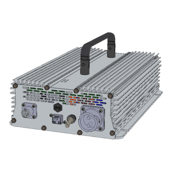
Main Parts Front Panel USB Communications Port Power Switch AC Output Connection: Amphenol DC Input Connection: Amphenol circu- circular MIL-spec GTS02R10SL-3P lar MIL-spec GTS02R-20-23P connector connector Remote Control Connection Top Panel Unit label location Indicator LEDs... -
Page 6: Operation
Operation This unit is designed for simple and intuitive operation. Before operating, the inverter must be properly installed and connected. See Installation and AC/DC Connections for more information. TO OPERATE THE INVERTER: Move the Power Switch to ON to energize the circuitry. The Invert LED and either the 50 Hz or 60 Hz LED will glow green indicating proper operation and the presence of AC power at the outputs. -
Page 7: Installation
Installation MOUNTING Mount the unit in a DRY and WELL VENTILATED area. Allow at least one inch (2.54 cm) of clearance all around the unit for adequate cooling. CAUTION: DO NOT MOUNT THE UNIT ANYWHERE EXPLOSIVE GASES CAN ACCUMULATE. A slight arc may occur when the power leads are connected, and in the unlikely event of a failure, sparks may be generated inside the unit. - Page 8 DC Connections IMPORTANT: BEFORE CONNECTING OR DISCONNECTING ANYTHING TO THE INVERTER, THE POWER SWITCH MUST BE TURNED OFF. DC INPUT CONNECTION This unit is equipped with an Amphenol circular MIL-spec GTS02R-20-23P connector to serve as a DC Input Connection. Connect the DC power source here using wiring suitable for the input amps.
-
Page 9: Offline Ups Option
Off-line UPS Option The Off-line UPS (Uninterruptible Power Source) is an optional feature for this product line. Inverters with the offline UPS feature are constructed with an AC Input connection and internal off-line AC Bypass circuit. In the event of external AC power failure so it can function as a backup power source supplying the connected load. - Page 10 Load AC Power Source Inverter Legend AC Current DC Current DC Power Source AC POWER FAILURE • The AC power source fails. • The inverter detects a voltage drop on the off-line bypass and automatically turns on and starts operation. The BYPASS LED will stop glowing. •...
-
Page 11: Inverterwizard (Optional)
InverterWizard (Optional) InverterWizard is optional software that can be used to adjust the inverter’s operating settings. InverterWizard is free-to-download from www.analyticsystems.com or available by emailing sales@analyticsystems.com Using InverterWizard, you can: • Set the inverter’s output frequency to either 50.00 or 60.00 Hz. •... -
Page 12: Troubleshooting
Troubleshooting This unit features eight LED indicators and an alarm buzzer to help diagnose any malfunctions during operation. In the event of malfunction, the alarm buzzer will sound prior to the inverter shutting down. You should immediately check which LEDs are glowing to determine the cause of the malfunction. -
Page 13: Specifications
Specifications Input Nominal Voltage 12 VDC 24, 28, 32, or 36 VDC 48 or 72 (Rail) VDC Actual Voltage 10.5-18 VDC 19 - 48 VDC 39 - 84 VDC Input Amps (Max.) 49 A 24 A 12 A 2x 30A 32 VDC Blade 1x 30A 58 VDC Blade Input Fuse (Internal) 1x MDA - 15A fuse... -
Page 14: Warranty
2 Years Parts and Labour Emissions Designed to meet MIL461F * Specifications subjects to change without notice. Designed and manufactured by: ANALYTIC SYSTEMS WARE (1993) LTD. 8128 River Way p. 604.946.9981 f. 604.946.9983 Delta, B.C. V4G 1K5 Canada tf. 800.668.3884 US/Canada www.analyticsystems.com... - Page 15 2 Years from date of manufacture for non-standard or OEM products 1 Year from date of manufacture for encapsulated products. 3. Analytic Systems will determine eligibility for warranty from the date of purchase shown on the warranty card when returned within 30 days, or...
- Page 16 DESIGNED AND MANUFACTURED BY 800-668-3884 604-946-9983 Support@analyticsystems.com www.analyticsystems.com Battery Chargers • Inverters • Power Supplies • Voltage Converters 101-8128 River Way Delta, BC V4G 1K5 | Canada Register Products Online | www.analyticsystems.com/support/warranty-registration...
Need help?
Do you have a question about the IPSi365M and is the answer not in the manual?
Questions and answers