Table of Contents
Advertisement
Quick Links
Advertisement
Table of Contents
Troubleshooting

Subscribe to Our Youtube Channel
Related Manuals for Analytic Systems Pure Sine 300


Summary of Contents for Analytic Systems Pure Sine 300
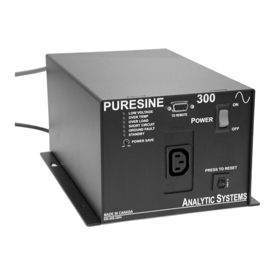
- Page 1 Pure Sine 300 Installation and Operation Manual 220 VAC Version Shown...
- Page 2 INTRODUCTION Computers are moving into non-traditional work areas at an ever increasing rate as more and more specialty software packages become available. However there is a major problem. Computers require clean, pure AC power to work reliably. If you power one from the same Genset that runs your heavy loads, you could damage it from surges and spikes generated by switching those loads.
-
Page 3: Specifications
Black Powder Epoxy Fastenings 18-8 Stainless Steel Weight 12.0 lb / 5.5 kg Designed and manufactured by: ANALYTIC SYSTEMS #207 12448 82 Ave. Surrey, BC, V3W 3E9, Canada phone (604) 543-7378 fax (604) 543-7354 toll free 800-668-3884 US/Canada email: info@analyticsystems.com; web site: www.analyticsystems.com... -
Page 4: Important Safety Instructions
Improper connection can result in a risk of an electric shock. Analytic Systems does not recommend the use of the IPS300 Series Pure Sine Inverters in life support applications where failure or malfunction of this product can be reasonably expected to cause failure of the life support device or to significantly affect its safety or effectiveness. -
Page 5: Installation
INSTALLATION MOUNTING Mount the unit in a DRY location. Mount the unit in a ventilated area. Allow at least 1 inch of clearance around the unit for adequate cooling. It is NOT recommended that the unit be secured until it has been tested under the intended load. -
Page 6: Output Connections
OUTPUT CONNECTIONS One standard AC receptacle is provided for connection of up to two devices. Ensure that the total average load does not exceed the continuous current rating of the unit. CAUTION: Do not apply AC voltage to the outlet. Damage caused by this action will not be covered under warranty. -
Page 7: Troubleshooting
TROUBLE SHOOTING This unit provides LED indicators and a buzzer to help diagnose any problems. The unit should sound the buzzer to alert you prior to shutting itself down. You should immediately check the indicators to determine the cause of the shutdown. LED INDICATORS •... -
Page 8: Troubleshooting Checklist
TROUBLE SHOOTING CHECKLIST 1. Use a voltmeter to measure the input voltage. The input should match the rating printed on the unit. 2. Ensure that the battery is connected correctly: Red to Positive, Black to Negative. 3. Check the specifications of the load to see what power it consumes and test it from a standard wall outlet. -
Page 9: Remote Connector
REMOTE CONNECTOR This connector is located on the front of the unit. Note: All switches are electronic (solid state) not mechanical relays. REMOTE CONTROL (OPTIONAL) A remote control panel may be connected to the inverter using a 9-pin D-connector which attaches to the front panel of the inverter. - Page 10 This page left intentionally blank.
- Page 11 This page left intentionally blank.
- Page 12 LIMITED WARRANTY The equipment manufactured by Analytic Systems Ware (1993) Ltd. (the “Warrantor”) is warranted to be free from defects in workmanship and materials under normal use and service. This warranty is in effect for 3 years from the date of purchase by the user (the “Purchaser”).
Need help?
Do you have a question about the Pure Sine 300 and is the answer not in the manual?
Questions and answers