Table of Contents
Advertisement
Available languages
Available languages
Quick Links
NEFL36CFH-1 / NEFL42CFH-1 / NEFL50CFH-1 / NEFL60CFH-1 / NEFL72CFH-1
SAFETY INFORMATION
WARNING
!
FIRE OR EXPLOSION HAZARD
If the information in these instructions are
not followed exactly, a fi re or explosion may
result causing property damage, personal
injury, or loss of life.
- Do not store or use gasoline or other
fl ammable vapors and liquids in the vicinity of
this or any other appliance.
INSTALLER:
Leave this manual with the appliance
CONSUMER:
Retain this manual for future reference
Wolf Steel Ltd., 24 Napoleon Rd., Barrie, ON, L4M 0G8 Canada / 103 Miller Drive, Crittenden, Kentucky, USA, 41030
$10.00
MULTIPLE PRODUCT CODES (LEAVE BLANK IF N/A)
Phone 1 (866) 820-8686 • www.napoleon.com • hearth@napoleon.com
INSTALLATION AND
ADD MANUAL TITLE
OPERATION MANUAL
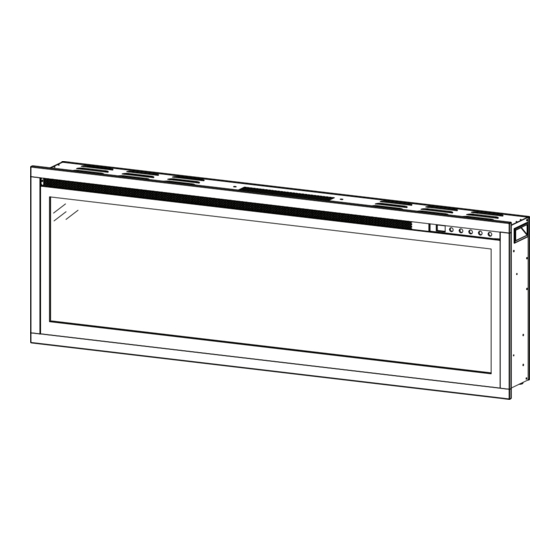
Entice-1 36 / 42 / 50 / 60 / 72 Series
ADD BUTTON BATTERY WARNING IF APPLICABLE
This appliance has a remote that requires button
batteries that are hazardous to young children.
CERTIFIED TO THE CANADIAN AND AMERICAN NATIONAL STANDARDS:
CERTIFIED TO THE CANADIAN AND AMERICAN NATIONAL STANDARDS:
CSA /
INTERTEK
LOGO
BARCODE LABEL ON THE OWNER'S MANUAL"
Product Name / Code
(MUST use title from Price Book)
(NEFL50CFH-1 Illustrated)
(IF MULTIPLE, _____ ILLUSTRATED)
ADD PRODUCT IMAGE
IF INSTALLATION + OPERATION, ADD SERIAL
NUMBER LABEL HERE
IF SEPARATE MANUALS, ADD "PLACE
ENGLISH
FRENCH PG. 37
FOR INDOOR USE ONLY
CSA 22.2 NO. 46 / UL 2021
CSA 22.2 NO. 46 / UL 1278
W415-4155 / - / 05.10.23
Advertisement
Chapters
Table of Contents

Related Manuals for Napoleon Entice-1 36 Series


Summary of Contents for Napoleon Entice-1 36 Series
- Page 1 INTERTEK LOGO BARCODE LABEL ON THE OWNER’S MANUAL” Wolf Steel Ltd., 24 Napoleon Rd., Barrie, ON, L4M 0G8 Canada / 103 Miller Drive, Crittenden, Kentucky, USA, 41030 Phone 1 (866) 820-8686 • www.napoleon.com • hearth@napoleon.com W415-4155 / - / 05.10.23...
- Page 2 safety information WARNING • If equipped with a heater, this appliance can be hot when operated and can cause severe burns if contacted. • Do not operate appliance before reading and understanding operating instructions. Failure to operate appliance according to operating instructions could cause fi re or injury. •...
- Page 3 safety information WARNING • To prevent a possible fi re, do not block air intakes or exhaust in any manner. Do not use on soft surfaces, like a carpet, where openings may become blocked. • Always plug appliances directly into a wall outlet/receptacle. Never use an extension cord or relocatable power tap (outlet/power strip).
-
Page 4: Table Of Contents
table of contents general information dimensions rating plate information label location listing approvals general instructions unpacking and testing the appliance hardware list appliance placement grounding the appliance installation overview installation minimum clearance to combustibles framing wall mount installation recessed installation 3.4.1 partially recessed installation 3.4.2 fully recessed installation electrical information... -
Page 5: General Information
model designation 1.0 general information dimensions W415-4155 / - / 05.10.23... -
Page 6: Rating Plate Information
DÉSIGNÉ EN AMÉRIQUE DU NORD BY WOLF STEEL LTD. PAR WOLF STEEL LTÉE. MADE IN CHINA FABRIQUÉ EN CHINE WOLF STEEL LTD. 24 NAPOLEON ROAD, SERIAL NUMBER/NO. DE SÉRIE: NEFLXXCFH-1 BARRIE, ON, L4M 0G8 CANADA W385-4597 note: The rating plate must remain with the appliance at all times. It must not be removed. -
Page 7: Listing Approvals
general information listing approvals This appliance has been tested in accordance with the CSA Standards for fi xed and location-dedicated electric room appliances in the United States and Canada. If you need assistance during installation, please contact your local dealer. note: This appliance must be electrically wired and grounded in accordance with local codes or, in the absence of local codes, with the latest edition of the National Electrical Code ANSI/NFPA 70 in the United States or the... -
Page 8: Unpacking And Testing The Appliance
general information unpacking and testing the appliance Carefully remove the appliance from the box and remove the support brackets. Prior to installing the appliance, remove all packaging material and test to make sure the appliance operates properly by plugging the power supply cord into a conveniently located 120V, 15 amp minimum grounded outlet. -
Page 9: Appliance Placement
2.0 appliance placement WARNING • Due to high temperatures, this electric appliance should be located out of traffi c. Keep combustible materials such as furniture, pillows, bedding, papers, clothes, curtains, and similar items at least 36” from the front of the appliance. -
Page 10: Installation Overview
appliance placement installation overview Your appliance is capable of three unique installation confi gurations: wall-mounted, partially recessed into the wall, and fully recessed into the wall. See below for details: Side View Front View Top Trim Wall-Mounted Installation Side Panel •... -
Page 11: Installation
3.0 installation WARNING • Risk of fi re! The power cord must not be pinched against a sharp edge. Secure cord to avoid tripping or snagging to reduce the risk of fi re, electric shock, or personal injury. Do not run cord under carpeting. Do not cover cord with throw rugs, runners, or similar items. -
Page 12: Framing
installation framing Finishing Material 16" 16" (406mm) (406mm) Finishing Material (Non-Load 4" (102mm) minimum Bearing) (partially recessed) 6" (152mm) minimum * (fully recessed) MODEL NO. NEFL36CFH-1 35 1/8” (892mm) NEFL42CFH-1 40 7/8” (1038mm) NEFL50CFH-1 48 7/8” (1241mm) NEFL60CFH-1 58 7/8” (1495mm) NEFL72CFH-1 70 7/8”... -
Page 13: Wall Mount Installation
installation wall mount installation Due to the many different materials used on different walls, it is highly recommended that you consult your local builder before you install this appliance on the wall. Select a location that is not prone to moisture and is located at least 36” (91.4cm) away from combustible materials such as curtains, drapes, furniture, bedding, paper, etc. - Page 14 installation 4 13/16” (123mm) 10 1/8” (257mm) Installation may vary by appliance size. NEFL36/42/50CFH bracket illustrated. Installation may vary by appliance size. Centre Ref. NEFL36CFH-1 NEFL42CFH-1 NEFL50CFH-1 NEFL60CFH-1 NEFL72CFH-1 5 3/8” (137mm) 8 1/4” (210mm) 12 1/4” (311mm) 8 3/4” (223mm) 14 3/4”...
- Page 15 installation With the wall mounting bracket installed, have two people lift the appliance up and insert the hooks on the bracket into the slots on the back of the appliance (Fig. 3-3). For illustrative purposes Wall only. Installation may vary by model size.
-
Page 16: Recessed Installation
installation recessed installation Due to the many different materials used on different walls, it is highly recommended that you consult your local builder before you install this appliance on the wall. note: It is recommended the walls of the appliance enclosure be fi nished (i.e. drywall) to avoid exposed insulation or vapour barrier coming in contact with the appliance. - Page 17 installation Wall Slotted Hole Framing Bracket Slotted Reverse view of appliance Hole in place (framing hidden Fig. 3-9 for clarity) Insert the appliance into the rough framing, and make sure the framing brackets fi t into the slotted holes of the side trim (Fig. 3-9). Secure two screws (supplied) through the two slot holes on each side of the appliance with the framing brackets (Fig.
-
Page 18: Fully Recessed Installation
installation 3.4.2 fully recessed installation Remove side trims and top trims (Fig. 3-11). Remove the power cord and complete hardwiring (see “hardwiring installation” section). For illustrative purposes only. Installation may vary by model size. Fig. 3-11 Remove side holding brackets by removing the screws from inside the appliance (Fig. 3-12). Reinstall the screws after removing from outer trim, Insert the appliance into the rough framing. -
Page 19: Electrical Information
4.0 electrical information hard-wiring installation WARNING • Turn off the appliance completely and let it cool down before servicing. Only a qualifi ed service person should service and repair this electric appliance. Hard-Wiring Connection If it is necessary to hard-wire this appliance, a qualifi ed electrician must remove the cord connection and wire the appliance directly to the household wiring. -
Page 20: Wiring Diagram (Nefl36Cfh-1)
electrical information wiring diagram (NEFL36CFH-1) W415-4155 / - / 05.10.23... -
Page 21: Wiring Diagram (Nefl42Cfh-1)
electrical information wiring diagram (NEFL42CFH-1) W415-4155 / - / 05.10.23... -
Page 22: Wiring Diagram (Nefl50Cfh-1)
electrical information wiring diagram (NEFL50CFH-1) W415-4155 / - / 05.10.23... -
Page 23: Wiring Diagram (Nefl60Cfh-1)
electrical information wiring diagram (NEFL60CFH-1) W415-4155 / - / 05.10.23... -
Page 24: Wiring Diagram (Nefl72Cfh-1)
electrical information wiring diagram (NEFL72CFH-1) W415-4155 / - / 05.10.23... -
Page 25: Finishing
5.0 fi nishing WARNING • Power supply service must be completed prior to fi nishing to avoid reconstruction. • Heat vents and air openings cannot be covered in any circumstances. front glass removal / installation note: It is recommended to have two people remove and install the front glass. Remove the two screws holding the glass retaining brackets in place (Fig. -
Page 26: Operating Instructions
6.0 operating instructions Once the appliance has been plugged into a grounded electrical outlet or hard-wired to a dedicated 120V power supply, it is ready to operate. note: Ensure the house circuit breakers for the power supply are turned on. In the event of a power failure, the appliance will lose its memory function and will reset to factory mode when the power returns. - Page 27 operating instructions Turns appliance on and off. Power Controls the fl ame colours. Settings: FB01 - Dark Orange FB02 - Tangerine FB03 - Scarlet FB04 - Aqua FB05 - Electric Blue Flame Colour FB06 - Blue FB07 - Bright Green FB08 - Magenta FB09 - Violet FB10 - Gold...
- Page 28 operating instructions Controls fl ame speed. Flame Speed Settings: S-3, S-4, S-5, S-1, S-2 Cycle the ember bed and fl ame colour synchronously. Settings: C01 - Dark Orange C02 - Tangerine C03 - Scarlet C04 - Aqua C05 - Electric Blue Colour Cycling C06 - Blue C07 - Bright Green...
-
Page 29: Maintenance
7.0 maintenance WARNING • Always disconnect the power and allow the electric appliance to cool before performing any cleaning, maintenance or relocation of this electric appliance. Turn controls to OFF and remove plug from outlet or turn off the house circuit breaker to electric appliance receptacle. •... -
Page 30: Replacement Parts
8.0 replacement parts WARNING • Failure to position the parts in accordance with this manual or failure to use only parts specifi cally approved with this appliance may result in property damage or personal injury. Contact your dealer for questions concerning prices and policies on replacement parts. Normally, all parts can be ordered through your Authorized dealer / distributor. -
Page 31: Nefl36/42/50/60/72Chf-1 Overview
replacement parts W415-4155 / - / 05.10.23... - Page 32 replacement parts Part Number Ref. Description Stocked NEFL36CFH-1 NEFL42CFH-1 NEFL50CFH-1 NEFL60CFH-1 NEFL72CFH-1 W300-0318- W300-0319- W300-0320- W300-0321- W300-0322- Front Glass Tempered W300-0417 W300-0418 W300-0419 W300-0420 W300-0421 Glass - Flame Stepper Motor W435-0090-SER Blower and Heater W010-0241 Assembly Plastic Strip - W497-1611- W497-1612- W497-1613- W497-1614-...
-
Page 33: Troubleshooting
9.0 troubleshooting WARNING • Turn off the appliance completely and let cool before servicing. Only a qualifi ed service person should service and repair this electric appliance. symptom problem solution Appliance will not Appliance is not plugged into an Check plug, and plug in the appliance if necessary. come on when electrical outlet. - Page 34 troubleshooting symptom problem solution Ember bed is Brightness not selected. See “operation” section. not glowing or Ember LED issue. Inspect the ember bed LEDs and replace, if necessary. dimming. Main PCB board issue. Inspect the main PCB board and replace, if necessary. LED fl...
-
Page 35: Warranty
Notwithstanding any provisions contained in the Premium Warranty, Napoleon responsibility under this warranty is defi ned as above, and it shall not in any event extend to any incidental, consequential, or indirect damages. - Page 36 NAPOLEON CELEBRATING OVER 40 YEARS OF HOME COMFORT PRODUCTS 7200, Route Transcanadienne, Montréal, Québec H4T 1A3 24 Napoleon Road, Barrie, Ontario, Canada L4M 0G8 214 Bayview Drive, Barrie, Ontario, Canada L4N 4Y8 103 Miller Drive, Crittenden, Kentucky, USA 41030 De Riemsdijk 22, 4004 LC Tiel, The Netherlands Phone: 1-866-820-8686 napoleon.com...
- Page 37 LOGO BARCODE LABEL ON THE OWNER’S MANUAL” Wolf Steel Ltd., 24 Napoleon Rd., Barrie, ON, L4M 0G8 Canada / 103 Miller Drive, Crittenden, Kentucky, USA, 41030 Téléphone 1 (866) 826 8686 • www.napoleon.com • hearth@napoleon.com W415-4155 / - / 05.10.23...
- Page 38 consignes de sécurité AVERTISSEMENT • Si équipé avec un chauffage, cet appareil peut être chaud lorsqu’il fonctionne et peut causer de graves brûlures en cas de contact. • Ne faites pas fonctionner l’appareil avant d’avoir lu et compris les instructions d’utilisation. L’incapacité de respecter les instructions pourrait causer un incendie ou des blessures corporelles.
- Page 39 consignes de sécurité AVERTISSEMENT • Pour prévenir les risques d’incendie, ne bloquez pas les entrées d’air et les sorties d’air de quelque manière que ce soit. Ne placez pas cet appareil sur une surface molle telle qu’un tapis où les ouvertures pourraient se bloquer.
- Page 40 table de matières information générale dimensions information à propos de la plaque d’homologation emplacement d’étiquette homologations instructions générales déballage et vérifi cation de l’appareil liste de pièces emplacement de l’appareil mise à terre de l’appareil vue d’ensemble d’installation installation dégagement minimal aux combustibles ossature installation de montage murale installation d’encastré...
-
Page 41: Information Générale
model designation 1.0 information générale dimensions W415-4155 / - / 05.10.23... -
Page 42: Information À Propos De La Plaque D'homologation
DÉSIGNÉ EN AMÉRIQUE DU NORD BY WOLF STEEL LTD. PAR WOLF STEEL LTÉE. MADE IN CHINA FABRIQUÉ EN CHINE WOLF STEEL LTD. 24 NAPOLEON ROAD, SERIAL NUMBER/NO. DE SÉRIE: NEFLXXCFH-1 BARRIE, ON, L4M 0G8 CANADA W385-4597 note: La plaque d’homologation doit rester avec l’appareil à tout instant. Elle ne doit pas être enlevée. -
Page 43: Homologations
information générale homologations Cet appareil a été testé selon les normes CSA pour les appareils électrique installés de façon permanentes et amovibles aux États-Unis et au Canada. Si vous avec besoin d’assistance durant l’installation, veuillez contacter votre détaillant local. note: Cet appareil doit être raccordé... -
Page 44: Déballage Et Vérifi Cation De L'appareil
information générale déballage et vérifi cation de l’appareil Retirez soigneusement l’appareil de la boîte et retirez les supports. Avant d’installer l’appareil, retirez tous les matériaux d’emballage et vérifi ez que l’appareil fonctionne correctement en branchant le cordon d’alimentation dans une prise de terre minimale de 120V, 15 ampères, mise à la terre. Cristaux Acryliques Panneaux de (petits &... -
Page 45: Emplacement De L'appareil
2.0 emplacement de l’appareil AVERTISSEMENT • En raison des températures élevées, cet apareil électrique doit être situé hors de circulation. Conservez des matériaux combustibles tels que des meubles, des coussins, les litières, des papiers, des vêtements, et des rideaux au moins 36” (91,4cm) de l’avant de l’appareil. •... -
Page 46: Vue D'ensemble D'installation
emplacement de l'appareil vue d’ensemble d’installation Votre appareil est capable de trois confi gurations d’installaion unique: monté au mur, encastré partiellement dans le mur, et encastré complètement dans le mur. Voir ci-dessous pour les détails: Vue de Côté Vue de Face Garniture Supérieure Installation de Montage Murale... -
Page 47: Installation
3.0 installation AVERTISSEMENT • Risque d’incendie! Le cordon d’alimentation ne doit pas être coincé contre une arrète vive. Fixez le cordon pour éviter les chutes ou les accrochages afi n de réduire le risque d’incendie, de choc électrique ou de blessures corporelles. -
Page 48: Ossature
installation ossature Matériel de Finition 16" 16" (406mm) (406mm) Matériel de Finition (Non Porteur) 4" (102mm) minimum (encastré partiellement) 6" (152mm) minimum * (encastré complètement) No. de Modèle NEFL36CFH-1 35 1/8” (892mm) NEFL42CFH-1 40 7/8” (1038mm) NEFL50CFH-1 48 7/8” (1241mm) NEFL60CFH-1 58 7/8”... -
Page 49: Installation De Montage Murale
installation installation de montage murale En raison de trops de matériels fi nis différentes utilisés sur les murs, il est extrêmement recommandé que vous consultez votre constructeur local avant que vous installez cet appareil sur le mur. Choisissez un endroit non sujet à l’humidité et situé au moins 36” (94,1cm) des articles combustibles, tels que les rideaux, les meubles, la literie, le papier, etc. - Page 50 installation 4 13/16” (123mm) 10 1/8” (257mm) L’installation peut différer par la taille de l’appareil. Centre Ref. NEFL36CFH-1 NEFL42CFH-1 NEFL50CFH-1 NEFL60CFH-1 NEFL72CFH-1 14 3/4” 5 3/8” (137mm) 8 1/4” (210mm) 12 1/4” (311mm) 8 3/4” (223mm) (375mm) 18” 24 13/16” 35 7/8”...
- Page 51 installation Avec le support de monage murale installé, demandez à deux personnes de soulever l’appareil et insérez les crochets sur le support dans les fentes à l’arrière de l’appareil (Fig. 3-3). À titre d’illustration seulement. Wall L’installation peut différer par la taille de modèle.
-
Page 52: Installation D'encastré
installation installation d’encastré En raison de trops de matériels fi nis différentes utilisés sur les murs, il est extrêmement recommandé que vous consultez votre constructeur local avant que vous installez cet appareil sur le mur. note: Afi n d’éviter la possibilité d’isolation exposé ou la barrière de vapeur qui entre en contact avec le corps de l’appareil, il est recommandé... - Page 53 installation Wall Trou Écumoire Support d’Ossature Trou Vue inverse de l’appareil en Écumoire place (l’ossature a été masqué Fig. 3-9 par souci de clarté). Retirez le cordon d’alimentation et complétez le branchement par câble (voir la section « branchement par câble »).
-
Page 54: Installation D'encastré Complètement
installation 3.4.2 installation d’encastré complètement Retirez les garnitures latéraux et supérieures (Fig. 3-11). Retirez le cordon d’alimentation et complétez le branchement par câble (voir la section « branchement par câble »). À titre d’illustration seulement. L’installation peut différer par la taille de modèle. Fig. -
Page 55: Information Électrique
4.0 information électrique branchement par câble WARNING • Coupez l’alimentation électrique à l’appareil et laissez-le refroidir avant d’effectuer un entretien. Seul un technicien de service qualifi é peut effectuer l’entretien ou la réparation de cet appareil électrique. Branchment par Câble Si c’est nécessaire de faire un branchement par câble, un électricien peut retirer le cordon d’alimentation de l’appareil et brancher ce dernier directement au câblage de la maison. -
Page 56: Schéma De Câblage (Nefl36Cfh-1)
information électrique schéma de câblage (NEFL36CFH-1) W415-4155 / - / 05.10.23... -
Page 57: Schéma De Câblage (Nefl42Cfh-1)
information électrique schéma de câblage (NEFL42CFH-1) W415-4155 / - / 05.10.23... -
Page 58: Schéma De Câblage (Nefl50Cfh-1)
information électrique schéma de câblage (NEFL50CFH-1) W415-4155 / - / 05.10.23... -
Page 59: Schéma De Câblage (Nefl60Cfh-1)
information électrique schéma de câblage (NEFL60CFH-1) W415-4155 / - / 05.10.23... -
Page 60: Schéma De Câblage (Nefl72Cfh-1)
information électrique schéma de câblage (NEFL72CFH-1) W415-4155 / - / 05.10.23... -
Page 61: Finitions
5.0 fi nitions AVERTISSEMENT • La raccordement par câble doit être complété avant la fi nition afi n d’éviter toute reconstruction. • Les entrées d’air et les sorties d’air de l’appareil ne doivent jamais être couvertes. enlèvement / installation du verre avant note: Il est recommandé... -
Page 62: Instructions De Fonctionnement
6.0 instructions de fonctionnement Une fois que l’appareil est branché dans une prise de courant mise à la terre ou câblé d’une source d’alimentation dédié 120V, il est prêt à fonctionner. note: Assurez-vous que les disjoncteurs de la maison pour la source d’alimentation sont allumés. Lors une panne de courant, l’appareil va perdre sa fonction de mémoire et va réinitialiser à... - Page 63 instructions de fonctionnement Allume / éteint l’appareil. Alimentation Contrôle les couleurs de la fl amme. Réglages: FB01 - Orange Foncé FB02 - Tangerine FB03 - Écarlate FB04 - Aigue-marine Couleur FB05 - Bleu Électrique Flamme FB06 - Bleu FB07 - Vert Vif FB08 - Magenta FB09 - Le Violet FB10 - Jaune Foncé...
- Page 64 instructions de fonctionnement Contrôle la vitesse de la fl amme. Vitesse de Flamme Réglages: S-3, S-4, S-5, S-1, S-2 Le lit de braises et la couleur de la fl amme sont synchronisés. Réglages: C01 - Orange Foncé C02 - Tangerine C03 - Écarlate C04 - Aigue-marine C05 - Bleu Électrique...
-
Page 65: Entretien
7.0 entretien AVERTISSEMENT • Coupez l’alimentation en gaz et l’alimentation électrique avant de procéder de l’appareil ou de le relocaliser. Tournez les contrôles à « OFF » et retirez la fi che de la prise de courant ou fermez le disjoncteur du circuit de votre appareil. -
Page 66: Pièces De Rechange
8.0 pièces de rechange AVERTISSEMENT • Omettre de positionner les pièces conformément à ce manuel ou d’utiliser uniquement des pièces spécifi quement approuvées pour cet appareil peut causer des dommages matériels ou des blessures corporelles. Contactez votre détaillant pour les questions concernant les prix et la disponibilité des pièces de remplace- ment. - Page 67 pièces de rechange W415-4155 / - / 05.10.23...
- Page 68 pièces de rechange No. de Pièce Réf. Description Stock NEFL36CFH-1 NEFL42CFH-1 NEFL50CFH-1 NEFL60CFH-1 NEFL72CFH-1 W300-0318- W300-0319- W300-0320- W300-0321- W300-0322- Verre Avant Verre trempé - W300-0417 W300-0418 W300-0419 W300-0420 W300-0421 Flamme Moteur W435-0090-SER Pas à Pas Assemblage de Chauffage et W010-0241 Ventilateur Bande W497-1611-...
-
Page 69: Guide De Dépannage
9.0 guide de dépannage AVERTISSEMENT • Coupez l’alimentation électrique à l’appareil et laissez-le refroidir avant d’effectuer un entretien. Seulement un technicien de service qualifi é peut effectuer l’entretien ou la réparation de cet appareil électrique. symptôme problème solution L’appareil L’appareil n’est pas branché Vérifi... - Page 70 guide de dépannage symptôme problème solution La luminosité du Éclat de fl amme n’est pas Voir la section « fonctionnement ». jeu de fl ammes sélectionné. est faible ou Problème avec les fl amme DELs. Vérifi ez les DELs et remplacez-les si nécessaire. inexistante.
-
Page 71: Garantie
10.0 garantie Les appareils électriques Napoléon sont fabriqués conformément aux normes strictes du Système de Gestion de la Qualité mondialement reconnu ISO 9001 : 2015. Les produits Napoléon sont conçus avec des composants et des matériaux de qualité supérieure, assemblés par des artisans qualifi... - Page 72 T IO ODUITS CONFORT 7200, Route Transcanadienne, Montréal, Québec H4T 1A3 24 Napoleon Road, Barrie, Ontario, Canada L4M 0G8 214 Bayview Drive, Barrie, Ontario, Canada L4N 4Y8 103 Miller Drive, Crittenden, Kentucky, USA 41030 De Riemsdijk 22, 4004 LC Tiel, Pays-Bas Téléphone: 1-866-820-8686...
Need help?
Do you have a question about the Entice-1 36 Series and is the answer not in the manual?
Questions and answers