Table of Contents
Advertisement
Quick Links
Advertisement
Table of Contents

Related Manuals for National Instruments NI PXI-8108


Summary of Contents for National Instruments NI PXI-8108
- Page 1 PXI-8221...
- Page 2 NI PXI-8108 User Manual NI PXI-8108 User Manual March 2010 372561E-01...
- Page 3 Thailand 662 278 6777, Turkey 90 212 279 3031, United Kingdom 44 (0) 1635 523545 For further support information, refer to the Technical Support and Professional Services appendix. To comment on National Instruments documentation, refer to the National Instruments Web site at and enter ni.com/info the info code feedback ©...
- Page 4 Warranty The NI PXI-8108 is warranted against defects in materials and workmanship for a period of one year from the date of shipment, as evidenced by receipts or other documentation. National Instruments will, at its option, repair or replace equipment that proves to be defective during the warranty period.
- Page 5 Operation of this hardware in a residential area is likely to cause harmful interference. Users are required to correct the interference at their own expense or cease operation of the hardware. Changes or modifications not expressly approved by National Instruments could void the user’s right to operate the hardware under the local regulatory rules.
-
Page 6: Table Of Contents
Introduction Benefits of PXI ......................1-1 NI PXI-8108 ........................1-2 Description ......................1-2 Functional Overview ..................1-2 NI PXI-8108 Functional Description ..........1-2 National Instruments Software ..................1-4 Chapter 2 Installation and Configuration Installing the NI PXI-8108 ....................2-1 How to Remove the Controller from the PXI Chassis ........2-4 BIOS Setup ........................2-5... - Page 7 Front Panel........................3-2 DVI-I ....................... 3-3 COM1......................3-5 Ethernet ......................3-6 Parallel Port..................... 3-7 Universal Serial Bus..................3-9 Trigger......................3-10 GPIB (IEEE 488.2) ..................3-11 ExpressCard/34 Slot..................3-13 Front Panel Features ...................... 3-15 Data Storage ........................3-15 NI PXI-8108 User Manual ni.com...
- Page 8 Common Configuration Questions General Questions......................4-1 Boot Options ........................4-1 Cables and Connections....................4-2 Software Driver Installation...................4-3 Upgrade Information......................4-4 PXI Configuration......................4-6 Chapter 5 Troubleshooting Appendix A Specifications Appendix B Technical Support and Professional Services Glossary Index © National Instruments Corporation NI PXI-8108 User Manual...
-
Page 9: About This Manual
National Instruments PXI-8108 embedded controller kit. How to Use the Documentation Set Begin by reading the NI PXI-8108 Installation Guide, a brief quick-start guide that describes how to install and get started with your controller. This manual, the NI PXI-8108 User Manual, contains more details about changing the installation or configuration from the defaults and using the hardware. -
Page 10: Related Documentation
ExpressCard Standard, Release 1.0, PCMCIA • Universal Serial Bus (USB) Specification, Revision 2.0 • Digital Visual Interface (DVI) Specification, Revision 1.0 • IEEE Std 488.1-2003, IEEE Standard for Higher Performance Protocol for the Standard Digital Interface for Programmable Instrumentation NI PXI-8108 User Manual ni.com... -
Page 11: Introduction
Additionally, PXI meets the more specific needs of instrumentation users by adding an integrated trigger bus and reference clock for multiple-board synchronization, a star trigger bus for very precise timing, and local buses for side-band communication between adjacent peripherals. © National Instruments Corporation NI PXI-8108 User Manual... -
Page 12: Ni Pxi-8108
NI PXI-8108 embedded computer. NI PXI-8108 Functional Description The NI PXI-8108 is a modular PC in a PXI 3U-size form factor. Figure 1-1 is a functional block diagram of the NI PXI-8108. Following the diagram is a description of each logic block shown. - Page 13 Super I/O Watchdog COM 1 Timer Figure 1-1. NI PXI-8108 Block Diagram The NI PXI-8108 consists of the following logic blocks on the CPU module and the I/O module. The CPU module has the following logic blocks: ® ™ •...
-
Page 14: National Instruments Software
The PXI Connector connects the NI PXI-8108 to the PXI/CompactPCI backplane. • The Super I/O block represents the other peripherals supplied by the NI PXI-8108. The NI PXI-8108 has one serial port, and an ECP/EPP parallel port. • The Gigabit Ethernet connects to either 10 Mbit, 100 Mbit, or 1,000 Mbit Ethernet interfaces. - Page 15 RTSI or PXI synchronization, self-calibration, messaging, and acquiring data to extended memory. For more information visit ni.com/daq National Instruments’ Modular Instruments use specialized drivers suited to each product’s specialization. Express VIs provide customized, interactive programming of instruments in a single interface and soft front panels provide an interface for testing the functionality of each instrument with no programming required.
- Page 16 Chapter 1 Introduction NI-VISA is the National Instruments implementation of the VISA specification. VISA is a uniform API for communicating and controlling USB, Serial, GPIB, PXI, VXI, and various other types of instruments. This API aids in the creation of portable applications and instrument drivers.
-
Page 17: Installation And Configuration
Consult your PXI chassis user manual for specific instructions and warnings. Plug in your chassis before installing the NI PXI-8108. The power cord grounds the chassis and protects it from electrical damage while you install the module. (Make sure the power switch is turned off.) - Page 18 1 Protective Screw Cap (4X) Figure 2-1. Removing Protective Screw Caps Make sure the injector/ejector handle is in its downward position. Align the NI PXI-8108 with the card guides on the top and bottom of the system controller slot. Caution Do not raise the injector/ejector handle as you insert the NI PXI-8108.
- Page 19 Raise the injector/ejector handle until the module firmly seats into the backplane receptacle connectors. The front panel of the NI PXI-8108 should be even with the front panel of the chassis. Tighten the four bracket-retaining screws on the top and bottom of the front panel to secure the NI PXI-8108 to the chassis.
-
Page 20: How To Remove The Controller From The Pxi Chassis
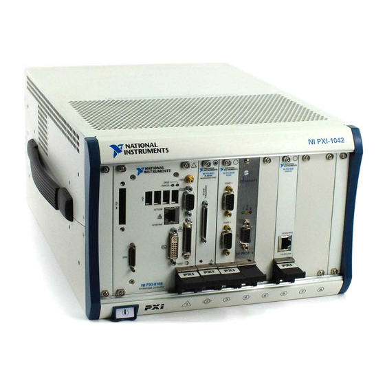
Chapter 2 Installation and Configuration Figure 2-2 shows an NI PXI-8108 installed in the system controller slot of a National Instruments PXI-1042 chassis. You can place PXI devices in any other slots. 1 PXI-1042 Chassis 2 NI PXI-8108 Controller 3 Injector/Ejector Rail Figure 2-2. -
Page 21: Bios Setup
The BIOS setup program includes menus for configuring settings and enabling NI PXI-8108 controller features. Most users do not need to use the BIOS setup program, as the NI PXI-8108 controller ships with default settings that work well for most configurations. -
Page 22: Main Setup Menu
Caution Changing settings in this menu may result in an unstable or unbootable controller. If this happens, follow the procedures outlined in the System CMOS section to restore BIOS settings to their factory defaults. NI PXI-8108 User Manual ni.com... -
Page 23: Sata Configuration Submenu
AHCI mode so that non-compatible OSes function correctly. The default value is AHCI. • Serial ATA Port 0—This item displays the onboard SATA drive detected in the system. © National Instruments Corporation NI PXI-8108 User Manual... -
Page 24: Cpu Configuration Submenu
Enabled. • Processor Type, Speed, and Number of Cores—These values indicate the type of processor used in the NI PXI-8108 controller, the speed of the processor, and the number of processor cores. Video Configuration Submenu Use this submenu to apply alternate settings to the video configuration. -
Page 25: Expresscard Configuration Submenu
When the controller is configured to boot LabVIEW RT, legacy USB support is automatically disabled. • Device Reset Delay—This setting specifies the number of seconds the Power-On Self Test will wait for a USB mass storage device to start. The default is 20 seconds. © National Instruments Corporation NI PXI-8108 User Manual... -
Page 26: Serial/Parallel Port Configuration Submenu
(IRQ) information for the onboard parallel port. • Device Mode—This settings enables alternate modes of operation for the parallel port. Usually the default setting works for all applications. The default is STD Printer Mode. NI PXI-8108 User Manual 2-10 ni.com... -
Page 27: Trigger Router Configuration Submenu
IP address or 169.254.x.x Disable Startup VI—If the controller becomes inaccessible because • of a startup VI, this switch can prevent VIs from automatically running at startup. The default is Use Switch Setting. © National Instruments Corporation 2-11 NI PXI-8108 User Manual... -
Page 28: Boot Setup Menu
Hard Drive BBS Priorities—Use this setting to access the Hard Drive BBS Priorities submenu to re-order or disable bootable hard drive devices. Refer to the Hard Drive BBS Priorities Submenu section for more information. NI PXI-8108 User Manual 2-12 ni.com... -
Page 29: Boot Settings Configuration Submenu
CD/DVD ROM drive devices. The highest priority device is displayed on the main Boot Option Priorities list. Optionally, each device can also be Disabled if the device should never be used as a boot device. © National Instruments Corporation 2-13 NI PXI-8108 User Manual... -
Page 30: Floppy Drive Bbs Priorities Submenu
User’s password is set, then this is a power on password and must be entered to boot or enter the BIOS setup program. In the BIOS setup program, the User will have Administrator rights. By default, no password is specified. NI PXI-8108 User Manual 2-14 ni.com... -
Page 31: Save & Exit Menu
If BIOS setup options have been changed and saved, a reboot will be required and the boot override selection will not be valid. © National Instruments Corporation 2-15 NI PXI-8108 User Manual... -
Page 32: System Cmos
Chapter 2 Installation and Configuration System CMOS The NI PXI-8108 contains a backed-up memory used to store BIOS configuration information. Complete the following steps to clear the CMOS contents: Power off the chassis. Remove the controller from the chassis. Press and hold down push-button switch SW2 for 2 to 3 seconds. -
Page 33: Labview Rt Installation
For information about configuring network settings, refer to the Configuring Network Settings book, accessible by browsing to MAX Remote Systems Help»LabVIEW Real-Time Target Configuration»Configuring Network Settings from the Contents tab of MAX Help. © National Instruments Corporation 2-17 NI PXI-8108 User Manual... - Page 34 Figure 2-4. Configuring RT Target Network Settings Expand the PXI controller view in the Remote Systems branch and select Software. Click the Add/Remove Software button in the toolbar to launch the LabVIEW Real-Time Software Wizard. NI PXI-8108 User Manual 2-18 ni.com...
-
Page 35: Labview Rt Configuration Switches
Note You must reboot the controller for any changes to take place. The NI PXI-8108 controller includes the following LabVIEW RT configuration switches: • Switch 1—Boot LabVIEW RT: Set this switch to ON to boot LabVIEW RT. - Page 36 The switches are shown in the OFF position. 1 Switch 1—Boot LabVIEW RT 3 Switch 3—Disable Startup VI 2 Switch 2—Boot Safe Mode 4 Switch 4—Reset IP Address Figure 2-5. LabVIEW RT Configuration Switches NI PXI-8108 User Manual 2-20 ni.com...
-
Page 37: Drivers And Software
PXI Features PXI Trigger Connectivity The SMB connector on the NI PXI-8108 front panel can connect to or from any PXI backplane trigger line. A trigger allocation process is needed to prevent two resources from connecting to the same trigger line, resulting in the trigger being double-driven and possibly damaging the hardware. -
Page 38: Chassis Configuration
PXI system. The configuration steps for single or multiple-chassis systems are the same. An example of a multichassis configuration is shown in Figure 2-6. Figure 2-6. Multichassis Configuration in MAX NI PXI-8108 User Manual 2-22 ni.com... -
Page 39: Basic Pxi System Configuration
PXI specification at www.pxisa.org Upgrading RAM You can change the amount of installed RAM on the NI PXI-8108 by upgrading the SO-DIMM. National Instruments offers the following types of SO-DIMMs for use with the NI PXI-8108 controller. -
Page 40: Hard Drive Recovery
Figure 2-7. Installing a DDR2 SO-DIMM in an NI PXI-8108 Controller Hard Drive Recovery The NI PXI-8108 controller ships with an OS Recovery CD that allows you to reinstall your operating system onto your hard drive through an external CD-ROM such as a USB CD-ROM drive. Boot the PXI controller using the OS re-installation CD to recover the OS. -
Page 41: Installing An Os
OS. When doing so, consider the following guidelines. Installing from a CD-ROM The NI PXI-8108 supports the installation of Windows 7, XP, and Vista from a USB CD-ROM. As an alternative to a USB CD-ROM drive, you can use an external SCSI CD-ROM with a PXI-SCSI adapter. -
Page 42: Removing An Expresscard
Caution To avoid data loss and other potential issues, stop communication with your ExpressCard device before removing it from the PXI-8108. In Windows, use the Safely Remove Hardware tool to safely stop the ExpressCard. NI PXI-8108 User Manual 2-26 ni.com... -
Page 43: I/O Information
I/O Information Front Panel Connectors Table 3-1 lists various I/O interfaces and their corresponding NI PXI-8108 external connectors, bus interfaces, and functions. Table 3-1. NI PXI-8108 I/O Overview I/O Interface External Connector Description Video DVI-I Intel Extreme Graphics (24-pin DSUB) -
Page 44: Front Panel
NI PXI-8108. Dimensions are in inches [millimeters]. 4.393 [111.58] 3.748 [95.2] 3.551 [90.2] 3.494 [88.76] 3.022 [76.76] 2.063 [52.4] 1.804 [45.82] 1.516 [38.51] 1.069 [27.15] NI PXI-8108 Embedded Controller .000 [0] Figure 3-1. NI PXI-8108 Front Panel Layout and Dimensions NI PXI-8108 User Manual ni.com... -
Page 45: Dvi-I
Chapter 3 I/O Information DVI-I Figure 3-2 shows the location and pinouts for the DVI-I connector on the NI PXI-8108. Table 3-2 lists and describes the DVI-I connector signals. 1 9 17 NI PXI-8108 Embedded Controller Figure 3-2. DVI-I Connector Location and Pinout Table 3-2. - Page 46 Ground (for +5 V) Hot Plug Detect TMDS Data0– TMDSData0+ TMDS Data0/5 Shield Reserved Reserved TMDS Clock Shield TMDS Clock+ TMDS Clock– Analog Red Analog Green Analog Blue Analog Horizontal Sync Analog GND Return: (analog R, G, B) NI PXI-8108 User Manual ni.com...
-
Page 47: Com1
Chapter 3 I/O Information COM1 Figure 3-3 shows the location and pinouts for the COM1 connector on the NI PXI-8108. Table 3-3 lists and describes the COM1 connector signal. COM1 NI PXI-8108 Embedded Controller Figure 3-3. COM1 Connector Location and Pinout Table 3-3. -
Page 48: Ethernet
Chapter 3 I/O Information Ethernet Figure 3-4 shows the location and pinouts for the Ethernet connector on the NI PXI-8108. Table 3-4 lists and describes the Ethernet connector signals. Ethernet NI PXI-8108 Embedded Controller Figure 3-4. Ethernet Connector Location and Pinout Table 3-4. -
Page 49: Parallel Port
1000 Mbit/sec data rate is selected. Parallel Port Figure 3-5 shows the location and pinouts for the IEEE 1284 (parallel) connector on the NI PXI-8108. Table 3-6 lists and describes the IEEE 1284 connector signals. Parallel port adapter cables are available from National Instruments, part number 777169-01. - Page 50 Data Bit 2 Data Bit 3 Data Bit 4 Data Bit 5 Data Bit 6 Data Bit 7 INIT# Initialize Printer STROBE# Strobe SLCTIN# Select Input AUTOFD# Auto Line Feed +5 V 19–35 Ground Not Connected NI PXI-8108 User Manual ni.com...
-
Page 51: Universal Serial Bus
Chapter 3 I/O Information Universal Serial Bus Figure 3-6 shows the location and pinouts for the Universal Serial Bus (USB) connectors on the NI PXI-8108. Table 3-7 lists and describes the USB connector signals. NI PXI-8108 Embedded Controller Figure 3-6. USB Connector Location and Pinout Table 3-7. -
Page 52: Trigger
The TRIG connector is the software-controlled trigger connection for routing PXI triggers to or from the backplane trigger bus. Figure 3-8 shows the TRIG connector location on the NI PXI-8108. Table 3-8 lists and describes the trigger connector signals. NI PXI-8108 Embedded Controller Figure 3-8. -
Page 53: Gpib (Ieee 488.2)
2 (Shield) Ground GPIB (IEEE 488.2) Figure 3-9 shows the location and pinouts for the GPIB connector on the NI PXI-8108. Table 3-9 lists and describes the GPIB connector signals. National Instruments provides a GPIB mating connector, part number 183285-0R2. GPIB... - Page 54 Not Data Accepted IFC# Interface Clear SRQ# Service Request ATN# Attention SHIELD Chassis ground DIO5# Data Bit 5 DIO6# Data Bit 6 DIO7# Data Bit 7 DIO8# Data Bit 8 REN# Remote Enable 18–25 Logic Ground NI PXI-8108 User Manual 3-12 ni.com...
-
Page 55: Expresscard/34 Slot
Chapter 3 I/O Information ExpressCard/34 Slot The NI PXI-8108 controller is equipped with an ExpressCard/34 slot on the front panel, which provides I/O expansion and options for removable storage, Ethernet, and a variety of other I/O. Figure 3-10 shows the location and pinouts for the ExpressCard/34 slot on the NI PXI-8108. - Page 56 CPPE# PE Presence REFCLK– Reference Clock – REFCLK+ Reference Clock + Ground PERn PE Data Receive – PERp PE Data Receive + Ground PETn PE Data Transmit – PETp PE Data Transmit + Ground NI PXI-8108 User Manual 3-14 ni.com...
-
Page 57: Front Panel Features
Chapter 3 I/O Information Front Panel Features The NI PXI-8108 controller has the following front-panel features: • A controller reset pushbutton (press the button to generate a reset to the controller) • Two front panel LEDs that show PC status –... -
Page 58: Common Configuration Questions
How do I check the configuration of the memory, hard drive, time/date, and so on? You can view these parameters in the BIOS setup. To enter the BIOS setup, reboot the NI PXI-8108 and press <Delete> during the memory tests. Refer to the Accessing BIOS Setup Utility... -
Page 59: Cables And Connections
There are some limitations when booting from a USB device. Windows XP can be installed from a USB CD-ROM, but earlier versions of Windows cannot. The NI PXI-8108 BIOS configures the USB devices so that they will work in a DOS environment. -
Page 60: Software Driver Installation
How do I connect a standard 25-pin LPT cable to the NI PXI-8108? The NI PXI-8108 uses a type C LPT connector. Most parallel port devices use a type A connector. To use a device with a standard type A LPT connector, you need to use a type C-to-type-A LPT adapter. -
Page 61: Upgrade Information
Chapter 4 Common Configuration Questions How do I install software from a CD? The compact size of the NI PXI-8108 does not allow for an integrated CD-ROM drive. You have the following options: • USB CD-ROM—You can install from a USB CD-ROM using a bootable installation CD. - Page 62 . For peripheral drivers, refer to KnowledgeBase 3H3COSD8 downloads ni.com My NI PXI-8108 does not have an internal floppy drive. Is there a way to use an external drive? Yes. The NI PXI-8108 controller supports and can boot from USB floppy drives.
-
Page 63: Pxi Configuration
Chapter 2, Installation and Configuration. Why doesn’t the NI PXI-8108 work with the PXI-8220 or PXI-8221? A serialized IRQ conflict with the PXI-8220/8221 and the NI PXI-8108 prevents PC cards using ISA interrupts from working with the NI PXI-8108 controller. For more information, refer to KnowledgeBase 2G3ED80Z at ni.com/support... -
Page 64: Troubleshooting
This chapter answers common troubleshooting questions you may have when using the NI PXI-8108 embedded computer. What if the NI PXI-8108 does not boot? Several problems can cause a controller not to boot. Here are some things to look for and possible solutions. - Page 65 Enter the BIOS setup program as described in the Accessing BIOS Setup Utility section of Chapter 2, Installation and Configuration. Check the battery utility. Press <F9> to load BIOS defaults. Answer Y (Yes) to the verification prompt. Select Save and Exit Setup. NI PXI-8108 User Manual ni.com...
- Page 66 Press and hold down push-button switch SW2 for 2 to 3 seconds. The switch location is shown in Figure 5-1. Reinstall the controller in the chassis. Push-Button Switch SW2 Figure 5-1. Clearing the CMOS Contents © National Instruments Corporation NI PXI-8108 User Manual...
-
Page 67: Appendix A Specifications
Specifications This appendix lists the electrical, mechanical, and environmental specifications of the NI PXI-8108 embedded computer. Features NI PXI-8108 ® ™ Intel Core 2 Duo processor T9400 (2.53 GHz dual core processor), 800 MHz FSB On-die L2 cache 6 MB... - Page 68 Slot requirements ........One system slot plus three controller expansion slots Compatibility ..........Fully compatible with PXI specification Weight ............0.914 kg (2.02 lb) typical Environment Maximum altitude........2,000 m (at 25 °C ambient temperature) Pollution Degree ........2 Indoor use only. NI PXI-8108 User Manual ni.com...
- Page 69 Relative humidity ......5% to 95%, noncondensing (Tested in accordance with IEC-60068-2-56.) For chassis that are not available in the online catalog at ni.com, contact National Instruments for supported operating temperatures. 5 to 40 °C for the PXI-1000B DC. © National Instruments Corporation...
- Page 70 EN 61326 (IEC 61326): Class A emissions; Basic immunity • EN 55011 (CISPR 11): Group 1, Class A emissions • AS/NZS CISPR 11: Group 1, Class A emissions • FCC 47 CFR Part 15B: Class A emissions • ICES-001: Class A emissions NI PXI-8108 User Manual ni.com...
- Page 71 Certification column. Environmental Management National Instruments is committed to designing and manufacturing products in an environmentally responsible manner. NI recognizes that eliminating certain hazardous substances from our products is beneficial not only to the environment but also to NI customers.
- Page 72 Instruments service representative. For more information about compliance with the EU Battery Directive 2006/66/EC about Batteries and Accumulators and Waste Batteries and Accumulators, visit ni.com/environment/batterydirective National Instruments (RoHS) National Instruments RoHS ni.com/environment/rohs_china (For information about China RoHS compliance, go to ni.com/environment/rohs_china NI PXI-8108 User Manual ni.com...
- Page 73 Technical Support and Professional Services Visit the following sections of the award-winning National Instruments Web site at for technical support and professional services: ni.com • Support—Technical support at includes the ni.com/support following resources: – Self-Help Technical Resources—For answers and solutions,...
- Page 74 You also can visit the Worldwide Offices section of to access the branch ni.com/niglobal office Web sites, which provide up-to-date contact information, support phone numbers, email addresses, and current events. NI PXI-8108 User Manual ni.com...
- Page 75 Glossary Symbol Prefix Value nano –9 µ micro – 6 –3 milli kilo mega giga tera Symbols ° Degrees. Ω Ohms. Percent. Amperes. Alternating Current. ASIC Application-specific integrated circuit. © National Instruments Corporation NI PXI-8108 User Manual...
- Page 76 Direct Current. DDR2 Double Data Rate, 2 generation. DIMM Dual In-line Memory Module. Direct Memory Access—A method by which data is transferred between devices and internal memory without intervention of the central processing unit. NI PXI-8108 User Manual ni.com...
- Page 77 2. A measure of acceleration equal to 9.8 m/s GPIB General Purpose Interface Bus (IEEE 488). A measure of random vibration—The root mean square of acceleration levels in a random vibration test profile. Hertz—Cycles per second. © National Instruments Corporation NI PXI-8108 User Manual...
- Page 78 Light-emitting diode. Meters. master A functional part of a PXI device that initiates data transfers on the PXI backplane. A transfer can be either a read or a write. NI PXI-8108 User Manual ni.com...
- Page 79 Mean time to repair. NI-488 or NI-488.2 The National Instruments software for GPIB systems. NI-DAQ The National Instruments software for data acquisition instruments. NI-VISA The National Instruments implementation of the VISA standard—An interface-independent software that provides a unified programming interface for VXI, GPIB, and serial instruments.
- Page 80 Static RAM—A memory chip that requires power to hold its content. It does not require refresh circuitry as a dynamic RAM chip, but it does take up more space and uses more power. Universal Serial Bus. NI PXI-8108 User Manual ni.com...
- Page 81 Glossary Volts. Video Graphics Array—The minimum video display standard for all PCs. Watts. © National Instruments Corporation NI PXI-8108 User Manual...
- Page 82 SATA Configuration menu, 2-7 general questions, 4-1 Save & Exit menu, 2-15 PXI configuration, 4-6 Serial/Parallel Port Configuration upgrade information, 4-4 menu, 2-10 CompactPCI specification, 1-1 Parallel Port menu, 2-10 Serial Port 0 menu, 2-10 © National Instruments Corporation NI PXI-8108 User Manual...
- Page 83 2-9 connector data storage, 3-15 location and pinout (figure), 3-13 DDR2 SO-DIMMs signals (table), 3-13 from National Instruments (note), 2-23, installing a module, 2-25 removing a module, 2-26 installing, 2-23, 4-4 slot, 1-4 figure, 2-24, 4-5 Declaration of Conformity (NI resources), B-2...
- Page 84 See also configuration connectors, 3-1 injector/ejector handle position (caution), 2-2 dimensions, 3-2 NI PXI-8108 installed in a PXI chassis features, 3-15 (figure), 2-4 functional description of NI PXI-8108, 1-2 procedure, 2-1 functional overview of NI PXI-8108, 1-2 removing NI PXI-8108 from PXI...
- Page 85 GPIB (IEEE 488.2) connector and installation overview, 2-25 signals, 3-11 os directory, 2-21 parallel port connector and signals, 3-7 trigger connector and signals, 3-10 Universal Serial Bus (USB) connector and signals, 3-9 data storage, 3-15 description, 1-2 NI PXI-8108 User Manual ni.com...
- Page 86 National Instruments software, 1-4 connectors, function (logic block), 1-4 NI resources, B-1 features, 2-21 NI-DAQmx, 1-5 trigger connectivity, 2-21 NI-VISA, 1-6 PXI-8220/PXI-8221, using NI PXI-8108 specifications with, 4-6 CE compliance, A-5 pxisys.ini file, 2-22 electrical, A-2 electromagnetic compatibility, A-4 environmental management, A-5...
- Page 87 4-3 using with PS/2 mouse and keyboard, 2-3 Universal Serial Bus (USB), 3-1, 3-9 connector function, 1-4 location and pinout (figure), 3-9 signals (table), 3-9 overview (table), 3-1 USB configuration menu, 2-9 NI PXI-8108 User Manual ni.com...
Need help?
Do you have a question about the NI PXI-8108 and is the answer not in the manual?
Questions and answers