Dimplex 500002573 Service Manual
Hide thumbs
Also See for 500002573:
- Installation and user manual (26 pages) ,
- Service manual (14 pages)
Table of Contents
Advertisement
Quick Links
IMPORTANT SAFETY INFORMATION:
fireplace. For your safety, always comply with all warnings and safety instructions contained in this manual to
prevent personal injury or property damage.
Service Manual
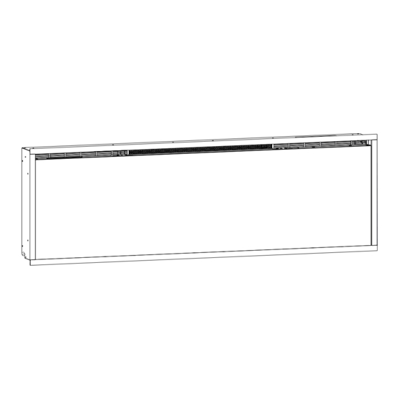
50" Model: 500002573
60" Model: 500002574
74" Model: 500002608
100" Model: 500002563
Always read this manual first before attempting to service this
UL Part Number
6914080100
6914090100
6914100100
6914110100
7401200100R00
Advertisement
Table of Contents

Related Manuals for Dimplex 500002573


Summary of Contents for Dimplex 500002573
- Page 1 Service Manual UL Part Number 50" Model: 500002573 6914080100 60" Model: 500002574 6914090100 74" Model: 500002608 6914100100 100" Model: 500002563 6914110100 IMPORTANT SAFETY INFORMATION: Always read this manual first before attempting to service this fireplace. For your safety, always comply with all warnings and safety instructions contained in this manual to prevent personal injury or property damage.
-
Page 2: Table Of Contents
500002573 (50" Model) ........ -
Page 3: Operation
Operation Press to turn on the unit or to put it in standby mode. Standby When the unit is turned back on, it will retain the previously used settings. Flame Effect Press to turn the flame effect, media, and media accent lights on or off. Press to turn the heat on or off. - Page 4 3 seconds to reset all the settings to Factory Reset factory default. This action will also disconnect the unit from the Wi-Fi network if connected. This action must be performed on the hidden touch controls . Figure 1 Figure 2 www.dimplex.com...
-
Page 5: Maintenence
Maintenance WARNING: Disconnect power and allow heater to cool before attempting any maintenance or cleaning to reduce the risk of fire, electric shock or damage to persons. ! NOTE: The fireplace should not be operated with an accumulation of dust or dirt on or in the unit, as this can cause a build up of heat and eventual damage. -
Page 6: Exploaded Parts Diagram
Media LED Media LED Replacement Parts List - 500002573 (50" Model) 1. Heater Assembly ....500002950 13. Flame LED 6-Light Assembly ..500002615 2. -
Page 7: 500002574 (60" Model)
Exploded Parts Diagram LED Configuration Flame LED Media LED Media LED Replacement Parts List - 500002574 (60" Model) 15. 4-Light RGBW Media LED Assembly X-3002350100RP 1. Heater Assembly ....500002950 16. -
Page 8: 500002608 (74" Model)
24. Driftwood Media ....500002841 12. 4-Light LED Flame Assembly ..500002606 13. 6-Light LED Flame Assembly (3) ..500002615 www.dimplex.com... -
Page 9: 500002563 (100" Model)
Exploded Parts Diagram LED Configuration Flame LED Media LED Media LED Replacement Parts List - 500002563 (100" Model) 15. Media Tray ....X-5902910300RP 1. -
Page 10: Wiring Diagrams
Wiring Diagrams 500002573 (50" Model) Heating Element Cut-outs Flicker Motor Relay Board 5 Amp Power Supply Hidden Touch Controls Main Control Board Media Bed LEDs Media Bed LEDs Flame LEDs 500002574 (60" Model) Heating Element Cut-outs Flicker Motor Relay Board... -
Page 11: 500002608 (74" Model)
Wiring Diagrams 500002608 (74" Model) Heating Element Cut-outs Flicker Motor Relay Board 5 Amp Power Supply Hidden Touch Controls Main Control Board Media Bed LEDs Media Bed LEDs Flame LEDs 500002563 (100" Model) Heating Element Cut-outs Flicker Motor 3 Amp Power Supply Relay Board Adapter... -
Page 12: Replacement Part Procedures
4. Remove the decorative media from the media tray, which lies along the bottom of the interior partially reflective glass. A medium sized container such as a bucket or a box will be needed to keep the decorative media together. www.dimplex.com... -
Page 13: Control Board Replacement
7. Reassemble in the reverse order as above. fireplace, and on the back of the Owner’s Manual. 9. Relink your fireplace to the Flame Connect App Figure 9 Control if desired. Visit dimplex .com/fcapp for more Board information. Figure 10 Relay... -
Page 14: Media Led Light Strips Replacement
8. Ensure that all wires are replaced in the same manner as 9. If lenses are not present on the new LED strip follow prior to the service. the following two steps before proceeding to step 10. (Figure 12) 9. Reassemble in the reverse order as above. www.dimplex.com... -
Page 15: Flicker Motor Replacement
Replacement Part Procedures Temperature Sensor (NTC) Replacment Figure 13 Tools required: Phillips head screwdriver Bushing 1. Follow “Preparation for Service” instructions before proceeding. 2. Locate the temperature sensor attached to the bracket in the upper left hand side of the unit. 3. -
Page 16: Troubleshooting
Defective relay board. Err 6 Fan error Defective heater assembly. Clean fan. Err 7 Fan is slow Defective heater assembly. Err 8 Element error Defective heater assembly. Element wire(s) is/are disconnected. Err 9 Element not detected Defective heater assembly. www.dimplex.com... -
Page 17: App
For troubleshooting information related to the Flame Connect app, please visit www .dimplex .com/fcapp 1-888-346-7539 | www.dimplex.com In keeping with our policy of continuous product improvement, we reserve the right to make changes without notice. © 2023 Glen Dimplex Americas A BRAND OF GLEN DIMPLEX AMERICAS...
Need help?
Do you have a question about the 500002573 and is the answer not in the manual?
Questions and answers